Downloaded 275 times


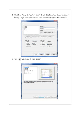
![2) GENERATING THE MODEL GEOMETRY
Select geometry from menu bar and click on ‘Nodes’ or we can add Nodes directly in
the Grid that appears in the main window.
4. Click on to View from +Z. [Can consider it as the Front view]
5. Draw the beam length using Snap Node.
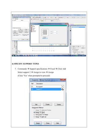
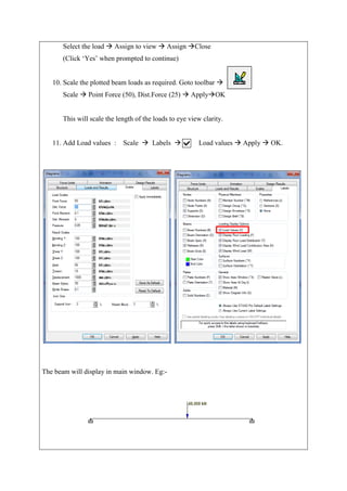
3) SPECIFY MEMBER PROPERTIES
6. From the file menu go to
Commands Member property Prismatic Rectangle
YD = 0.4 m
ZD = 0.3 m
Click, Add Close
Click, Assign to view Assign Close
(Click ‘Yes’ when prompted to continue.)](https://image.slidesharecdn.com/expno1analysisofsimplebeamusingstaadpro-170617135738/85/Analysis-of-simple-beam-using-STAAD-Pro-Exp-No-1-6-320.jpg)
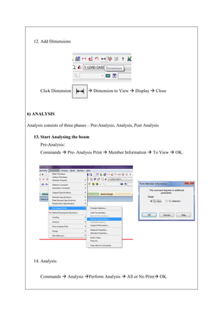
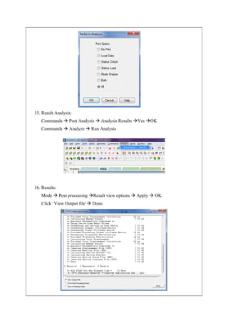
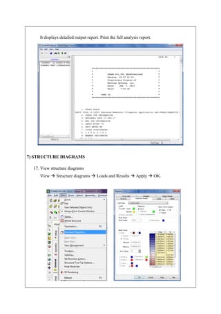

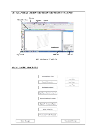
The document describes analyzing a simple beam using STAAD.Pro software. It discusses the steps taken, which include generating the beam model geometry by adding nodes and a member, specifying member properties and support types, applying loads, performing analysis, and viewing the results in the form of structure diagrams showing values like bending moment and shear force. The overall aim was to familiarize the user with STAAD.Pro's interface and analyze a basic beam structure.