Downloaded 552 times


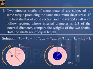
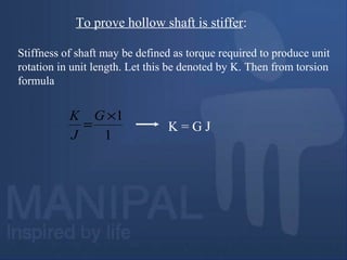
![D1
2D1/3
τMAXT
Considering the hollow shaft :
=
T J π.[D1
4
– (2D1/3)4
] /32 65π.D1
3
τmax R D1/2 1296
= = ----- (2)
Equating (1) and (2),
πD3
65πD1
3
16 1296
= => D = 0.93D1.](https://image.slidesharecdn.com/torsion-180511185446/85/Torsion-27-320.jpg)
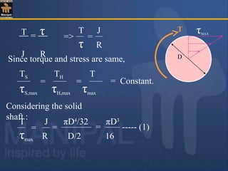
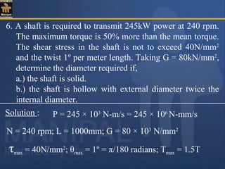
![Weight of hollow shaft,
=WH π.[D1
2
– (2D1/3)2
] × L × ρ
4
=WH 5πD1
2
× L × ρ
36
----- (4)
Weight of solid shaft, =WS πD2
× L × ρ
4
----- (3)](https://image.slidesharecdn.com/torsion-180511185446/85/Torsion-28-320.jpg)
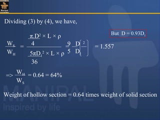
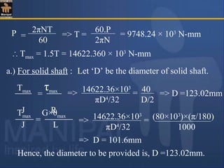
![For solid shaft, torque resisted is,
JS ×τ
R
TS = =
(πD4
/32) τ
D/2
=> =TS
τ× πD3
16
For hollow shaft, torque resisted is,
JH ×τ
R
TH = =
[π(D1
4
–D2
4
)/32]×τ
D1/2
=> =TH
τ × π(D1
4
–D2
4
)
16D1
∴ TH D1
4
– D2
4
TS D3
× D1
=
Substituting (1) in the above equation we have,
∴ TH D1
4
– D2
4
TS (D1
2
– D2
2
)3/2
. D1
= [ Since D = (D1
2
– D2
2
)1/2
]](https://image.slidesharecdn.com/torsion-180511185446/85/Torsion-31-320.jpg)

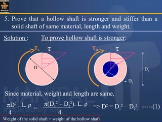
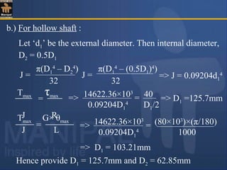
![Hence hollow shafts are stiffer than solid shafts of
same material, length and weight.
∴ KH D1
4
– D2
4
KS D4
=
=
(D1
2
– D2
2
)(D1
2
+ D2
2
)
(D1
2
– D2
2
)2
=
D1
4
– D2
4
(D2
)2
=>
KH D1
2
+ D2
2
KS D1
2
– D2
2
= > 1 => KH > KS
Stiffness of hollow shaft is, KH = G × JH = G [π(D1
4
-D2
4
)/32]
Stiffness of solid shaft is, KS = G × JS = G [πD4
/32]](https://image.slidesharecdn.com/torsion-180511185446/85/Torsion-34-320.jpg)
![Weight of hollow shaft,
= 33682.011 ρ L
∴ Percentage saving in weight, =
WS – WH
WS
× 100
= 43.62%
*************************************************
=WH π.[DE
2
– DI
2
] × L × ρ
4](https://image.slidesharecdn.com/torsion-180511185446/85/Torsion-40-320.jpg)
![T49
Contd..
EXERCISE PROBLEMS :
1. A hollow shaft 75mm outside diameter and 50mm inside
diameter has a maximum allowable shear stress of
90N/mm2
. What is the maximum power that can be
transmitted at 500 rpm ?
[Ans : 312.93 kW or 417 H.P.]
2. Determine the diameter of a solid circular shaft which
has to transmit a power of 90 H.P at 210 rpm. The
maximum shear stress is not to exceed 50MPa and the
angle of twist must not be more than 1º in a length of 3m.
Take G = 80GPa.
[Ans : D = 119 mm.]](https://image.slidesharecdn.com/torsion-180511185446/85/Torsion-41-320.jpg)
![T50
Contd..
3. Find the diameter of the shaft required to transmit 12kW
at 300 rpm if the maximum torque is likely to exceed the
mean torque by 25%. The maximum permissible shear
stress is 60N/mm2
. Taking G = 0.84 × 10⁵
N/mm2
, find
the angle of twist for a length of 2m.
[Ans : θ = 4.76º.
A solid shaft of circular cross-section transmits 1200kW at
100 rpm. If the allowable stress in the material of the
shaft is 80MPa, find the diameter of the shaft.
If the hollow section of the same material, with its
inner diameter (5/8)th
of its external diameter is adopted,
calculate the economy achieved.
[Ans : D = 194mm; % Saving in material = 31.88%]](https://image.slidesharecdn.com/torsion-180511185446/85/Torsion-42-320.jpg)
![T51
Contd..
5. A hollow shaft of diameter ratio 0.6 is required to
transmit 600 kW at 110 rpm. The maximum torque being
12% more than the mean. The shearing stress is not to
exceed 60MPa and the twist in the length of 3m not to
exceed 1º. Calculate the maximum external diameter of
the shaft. G = 80GPa.
[Ans : 190.3mm]
6. During test on sample of steel bar 25mm in diameter, it is
found that the pull of 50kN produces a extension of
0.095mm on the length of 200mm and a torque of
20×104
N-mm produces an angular twist of 0.9º on a
length of 0.25m. Find the Poisson’s ratio, modulus of
elasticity and modulus of rigidity for the material.
[Ans : µ = 0.25; E =214.5GPa; G = 83GPa.]](https://image.slidesharecdn.com/torsion-180511185446/85/Torsion-43-320.jpg)
![T52
Contd..
7. A solid aluminium shaft 1m long and 60mm diameter is
to be replaced by a tubular steel shaft of same length and
same outside diameter (60mm) such that each of the two
shaft could have same angle of twist per unit torsional
moment over the total length. What must be the inner
diameter of the tubular shaft if GS = 4GA.
[Ans : Di = 45.18mm]
8. A hollow shaft has diameters DE = 200mm and DI = 150
mm. If angle of twist should not exceed 0.5º in 2m and
maximum shear stress is not to exceed 50MPA, find the
maximum power that can be transmitted at 200 rpm. Take
G = 84GPa.
[Ans : 823kW]](https://image.slidesharecdn.com/torsion-180511185446/85/Torsion-44-320.jpg)
![T53
9. A hollow marine propeller shaft turning at 110 rpm is
required to propel a vessel at 12m/s for the expenditure of
6220kW, the efficiency of the propeller being 68 percent.
The diameter ratio of the shaft is to be (2/3) and the direct
stress due to thrust is not to exceed 8MPa. Calculate
(a) the shaft diameters
(b) the maximum shearing stress due to torque.
[Ans : DI = 212mm; DE = 318mm; τMAX = 10.66 MPa]
*************************************************](https://image.slidesharecdn.com/torsion-180511185446/85/Torsion-45-320.jpg)

1. The document discusses torsion of circular shafts, including pure torsion, assumptions in the theory of pure torsion, torsion formula, polar modulus, torsional rigidity, power transmitted by shafts, and numerical problems and solutions. 2. Key concepts covered include shear stress distribution in shafts under torsion, relationship between applied torque, shear stress, polar moment of inertia, and angle of twist. 3. Formulas are derived for calculating torque, shear stress, polar modulus, and torsional rigidity of solid and hollow circular shafts.


![MTORSION [EngineeringDuniya.co MTORSION [EngineeringDuniya.com].pptm].ppt](https://cdn.slidesharecdn.com/ss_thumbnails/mtorsionengineeringduniya-241112074730-b7e902c3-thumbnail.jpg?width=640&height=640&fit=bounds)


![3_torsion [Read-Only] [Compatibility Mode].pdf](https://cdn.slidesharecdn.com/ss_thumbnails/3torsionread-onlycompatibilitymode-240505061844-ecf49736-thumbnail.jpg?width=640&height=640&fit=bounds)


