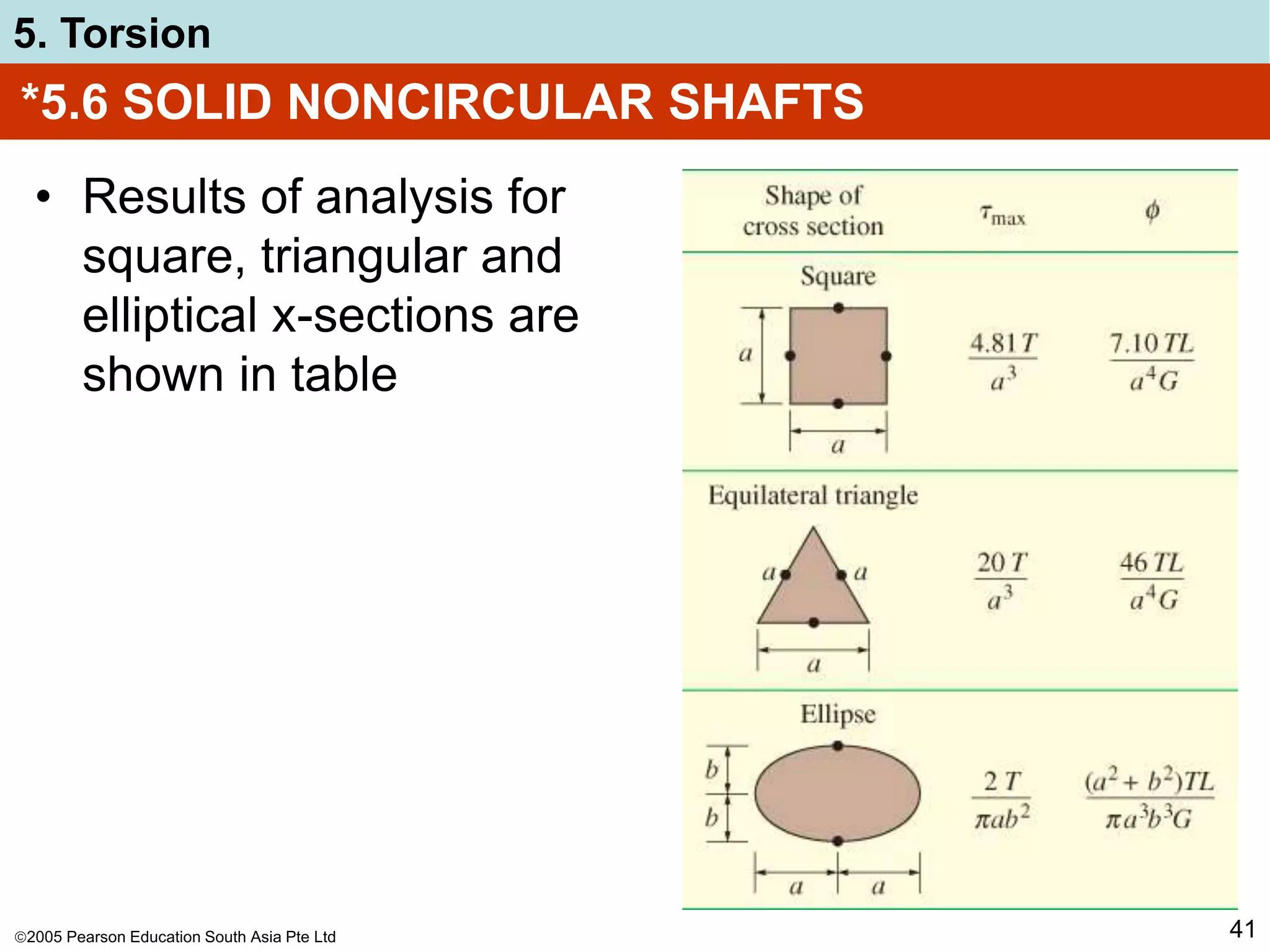
The document discusses torsion and shafts. It covers torsional deformation of circular shafts, the torsion formula for determining shear stress, power transmission through shafts, and the angle of twist. Examples are provided to demonstrate how to use the torsion formula to calculate shear stress and size shafts based on power requirements. Procedures are outlined for analyzing statically indeterminate shafts under torsional loading.
![2005 Pearson Education South Asia Pte Ltd
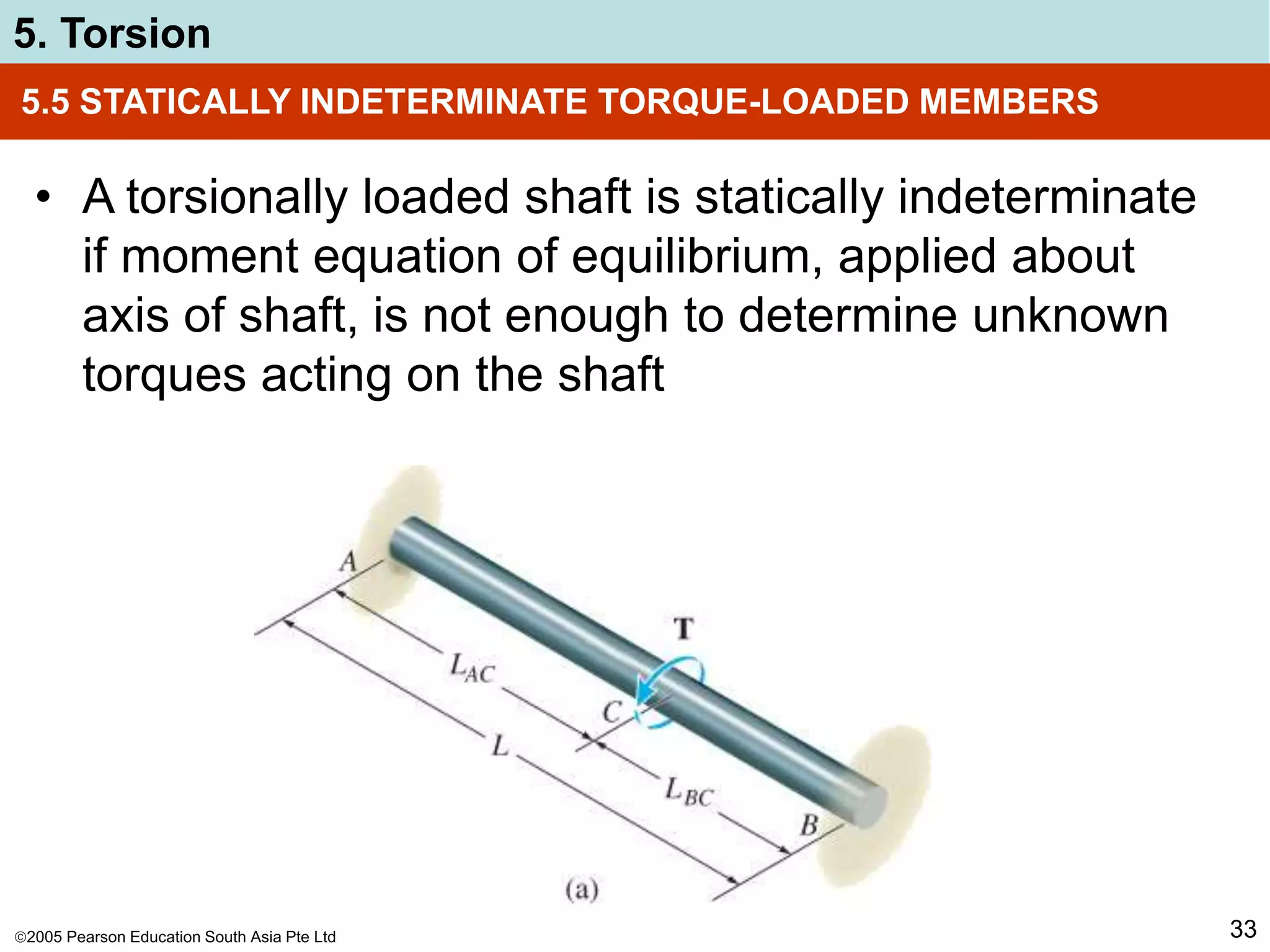
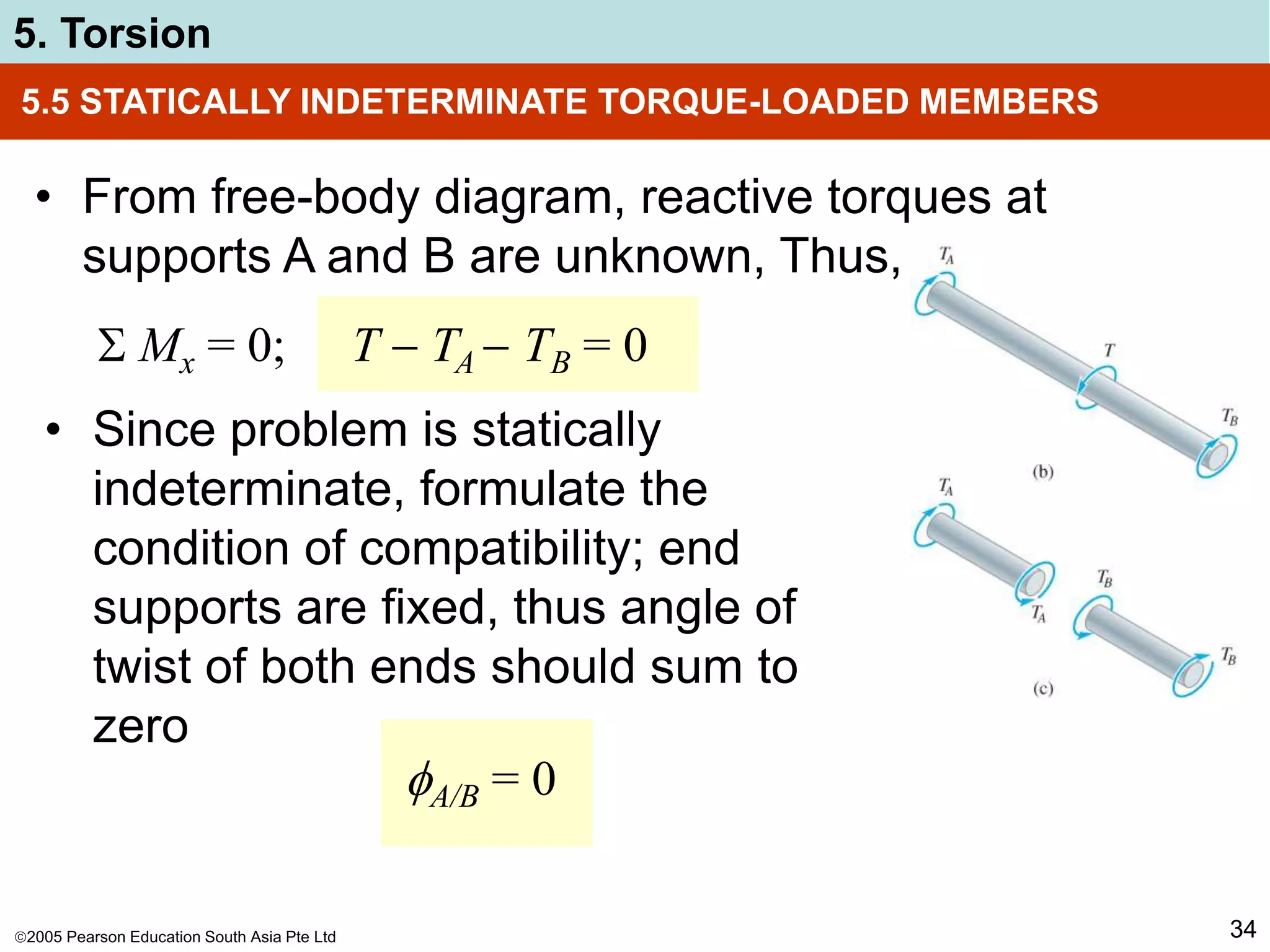
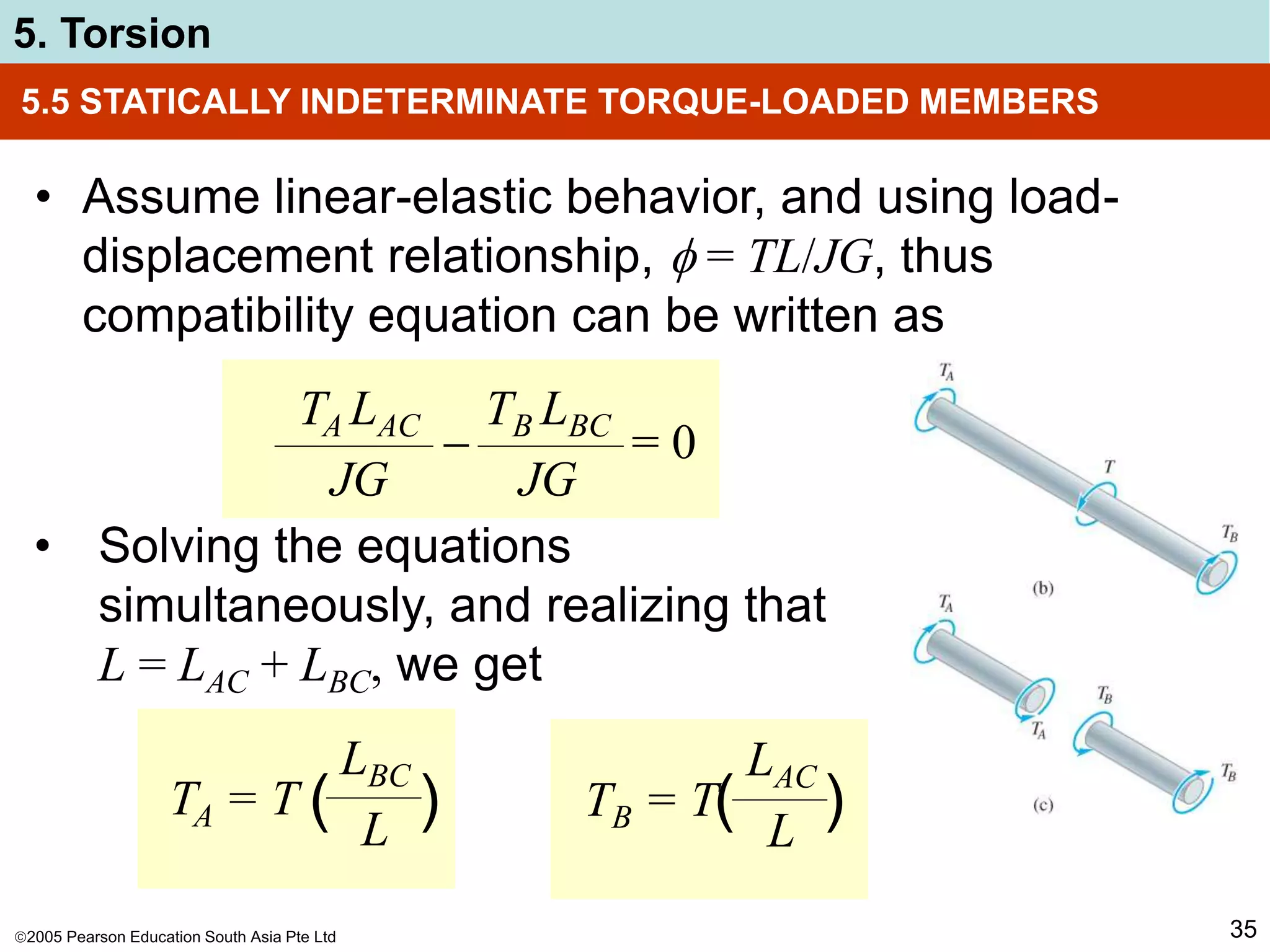
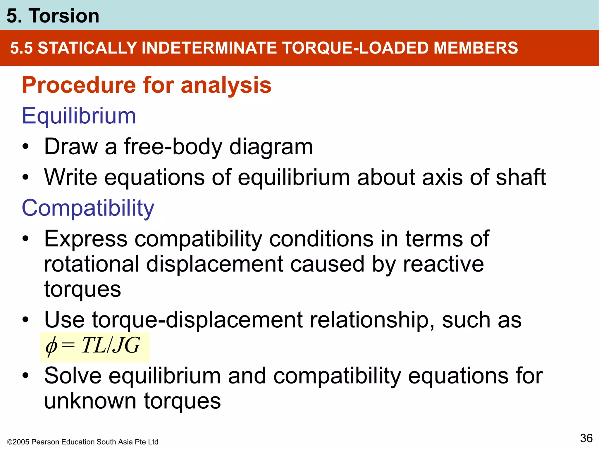
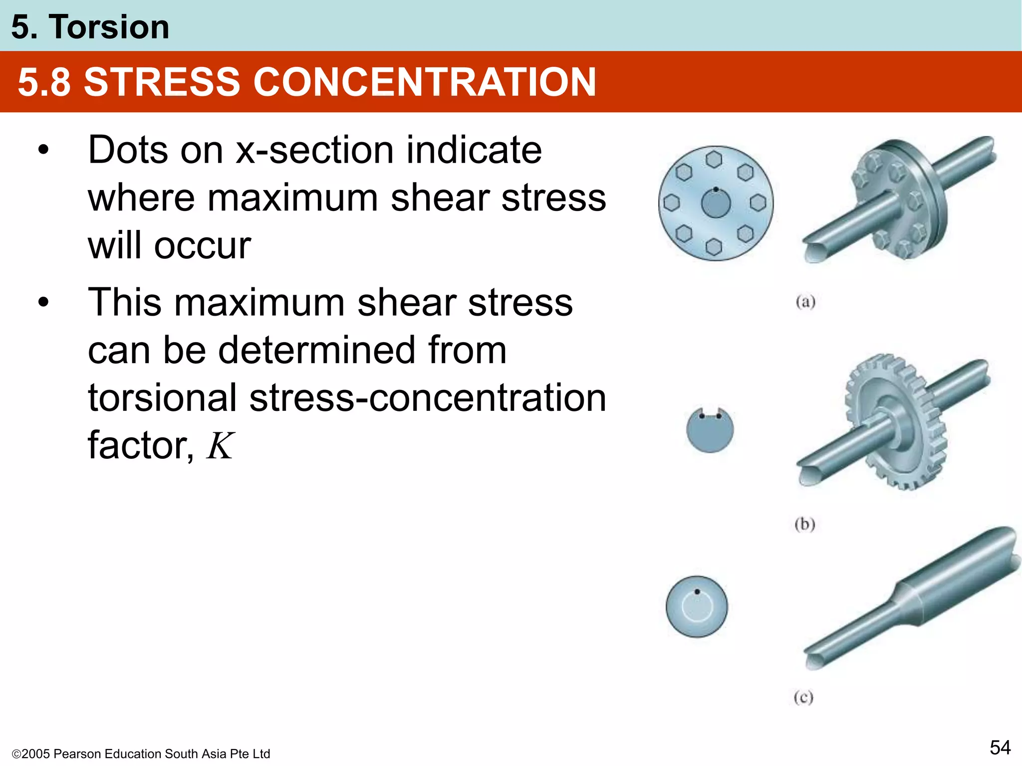
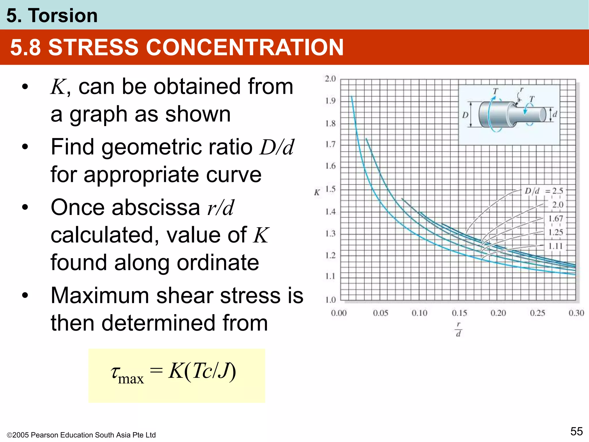
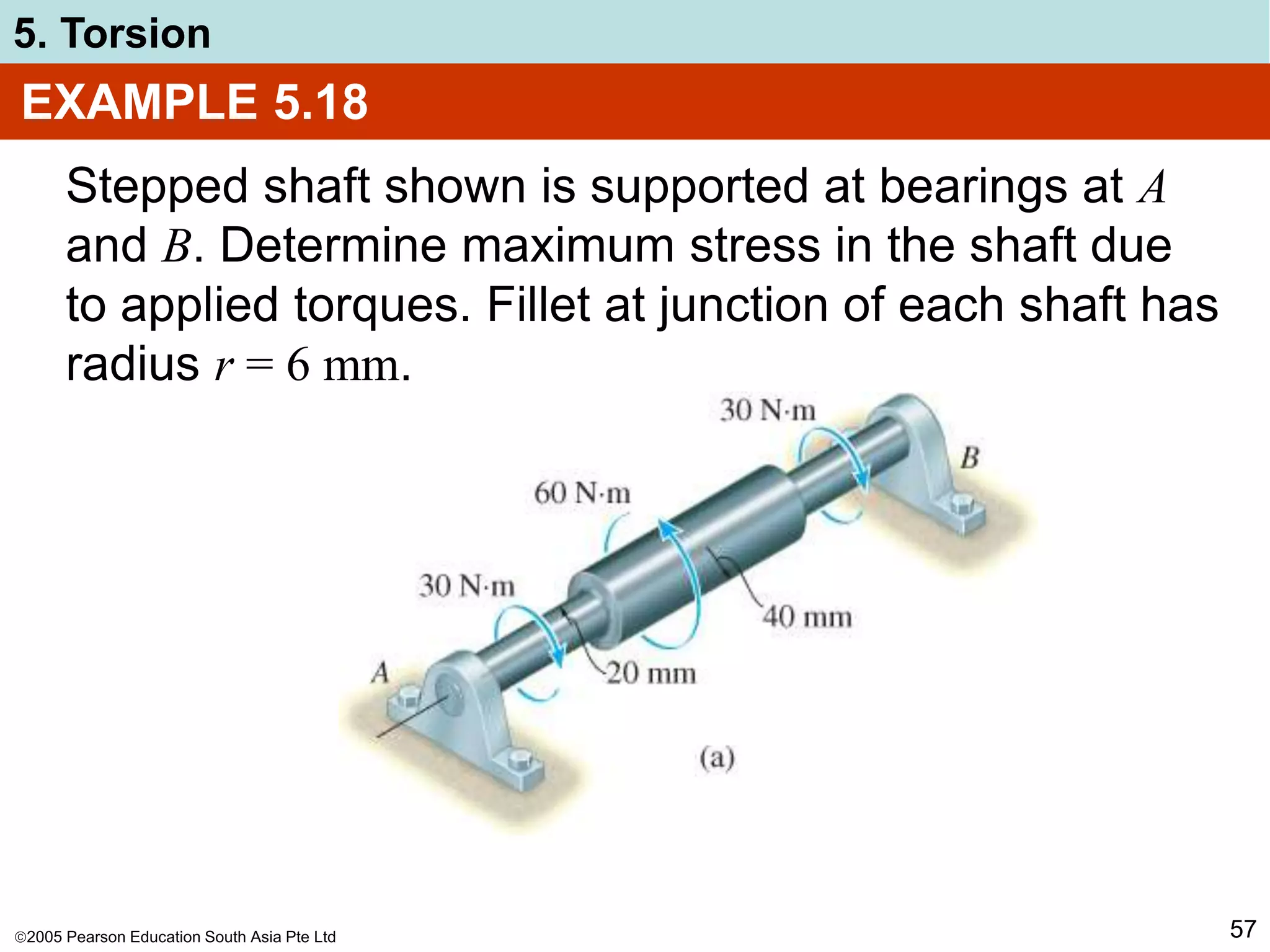
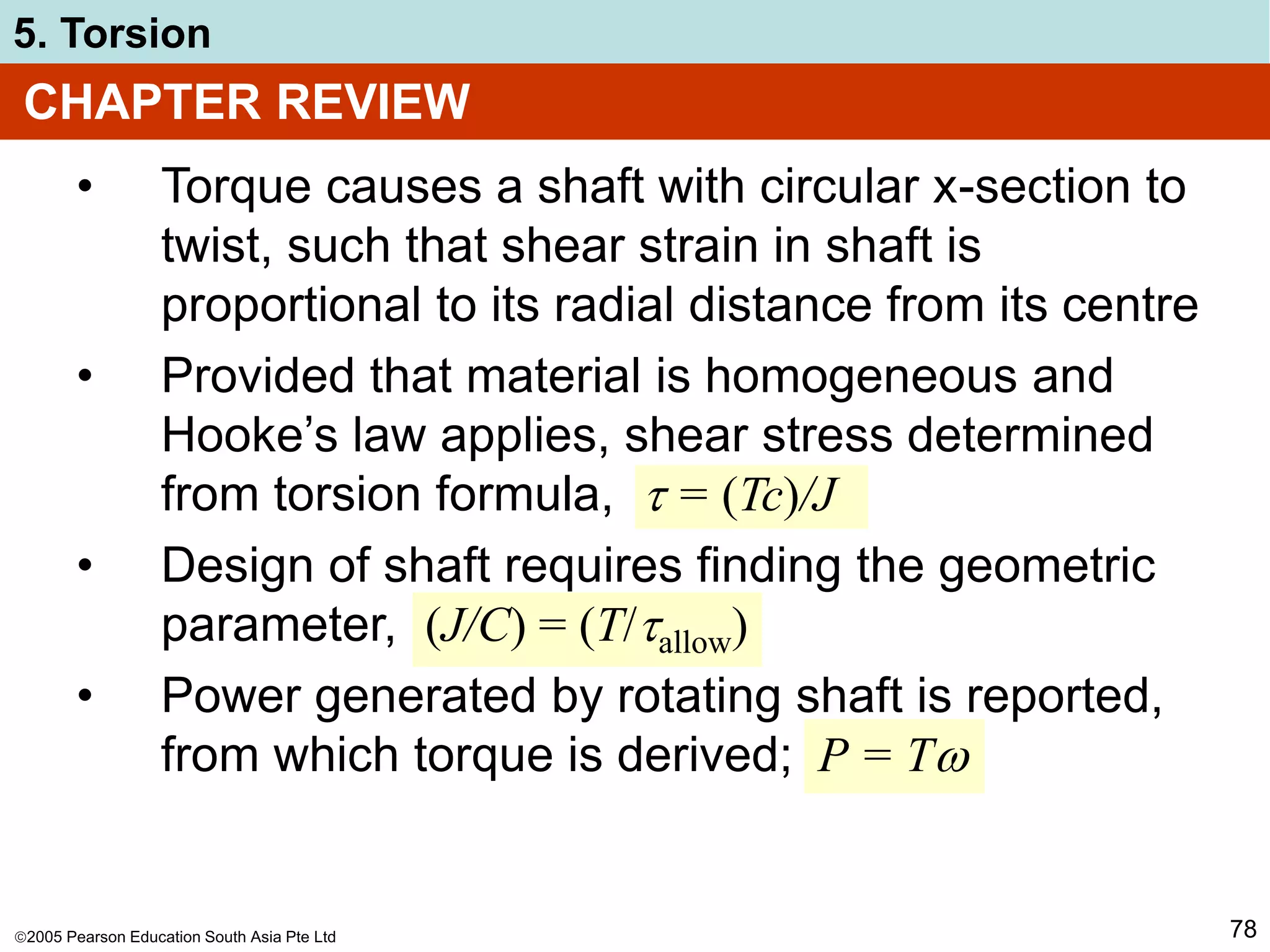
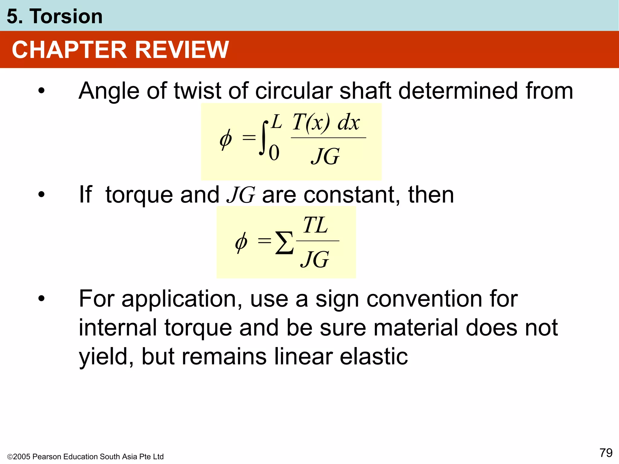
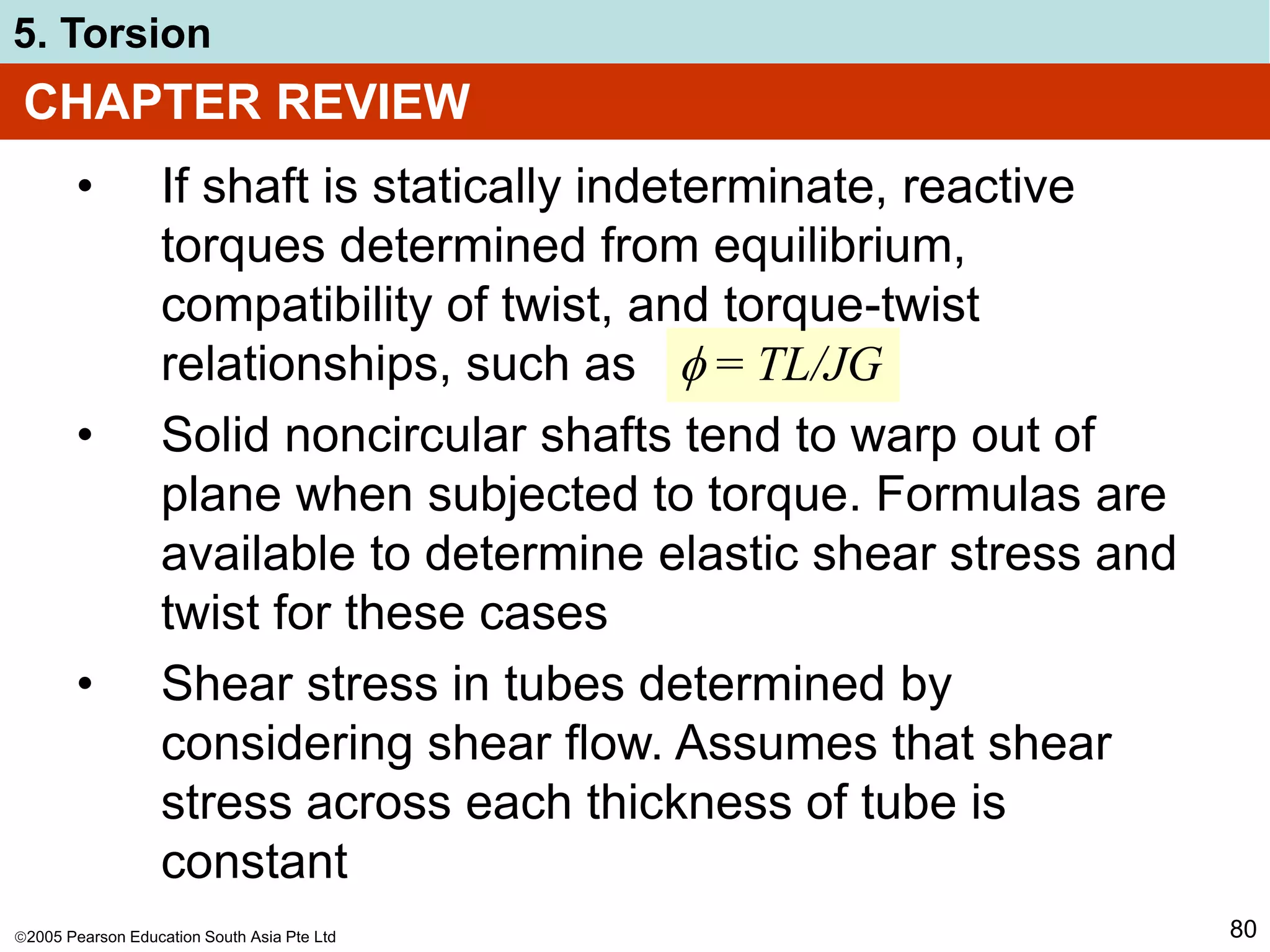
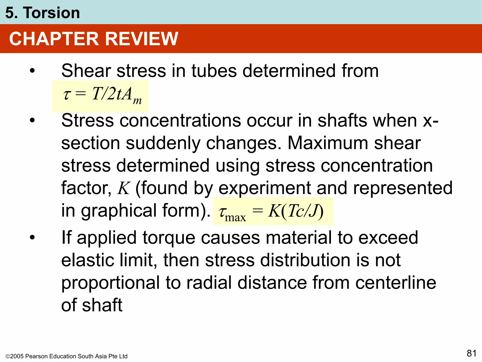
5. Torsion
52
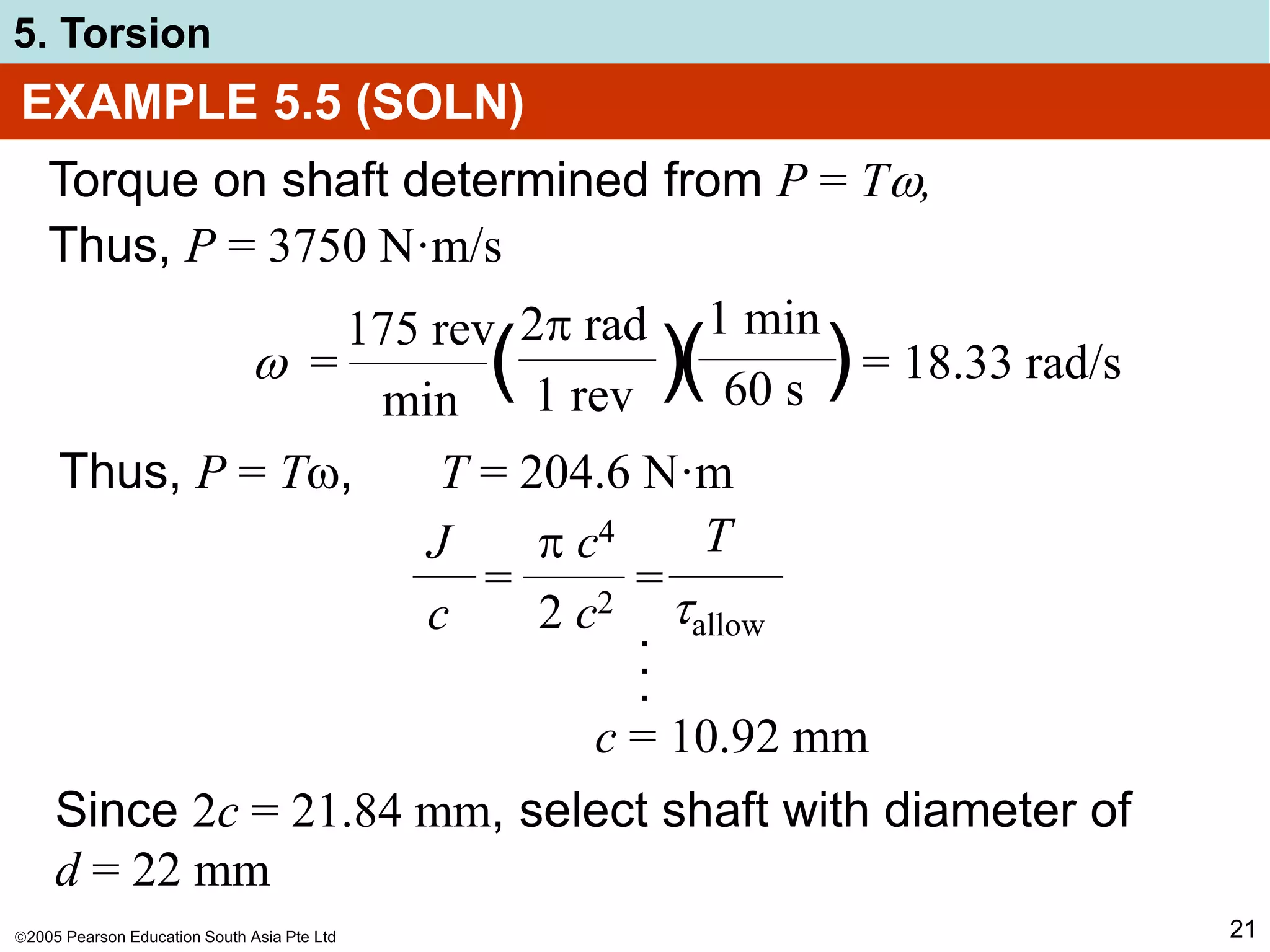
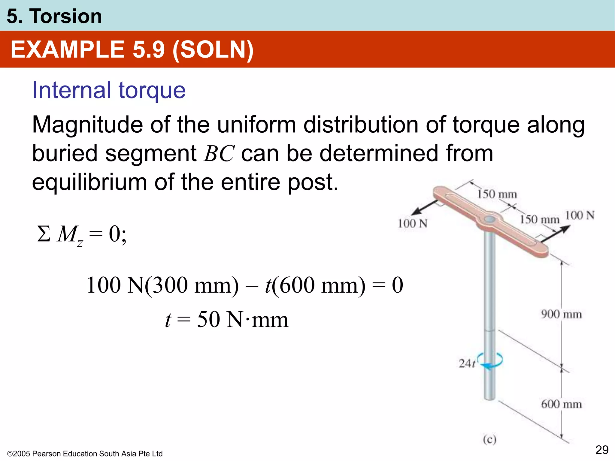
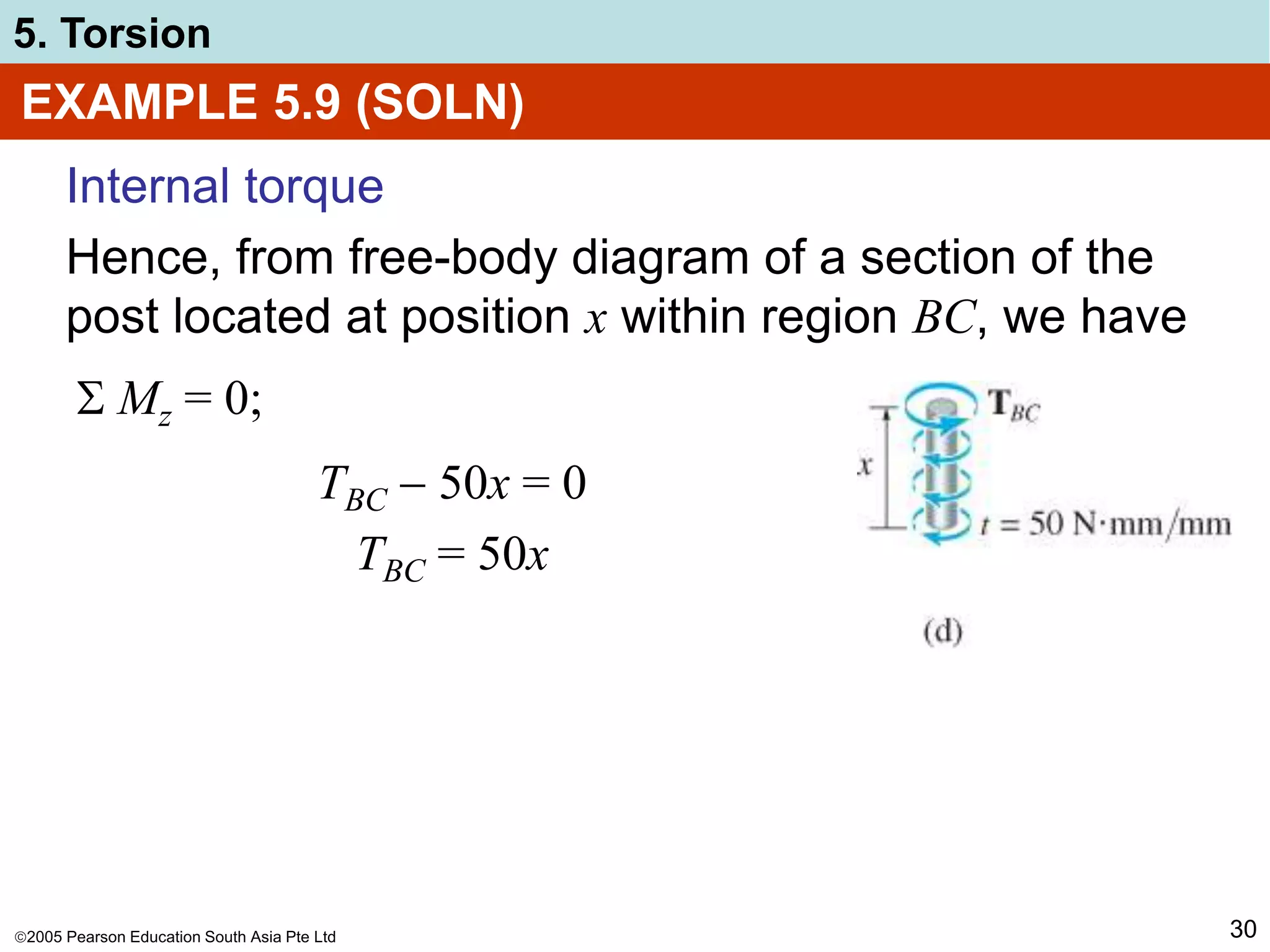
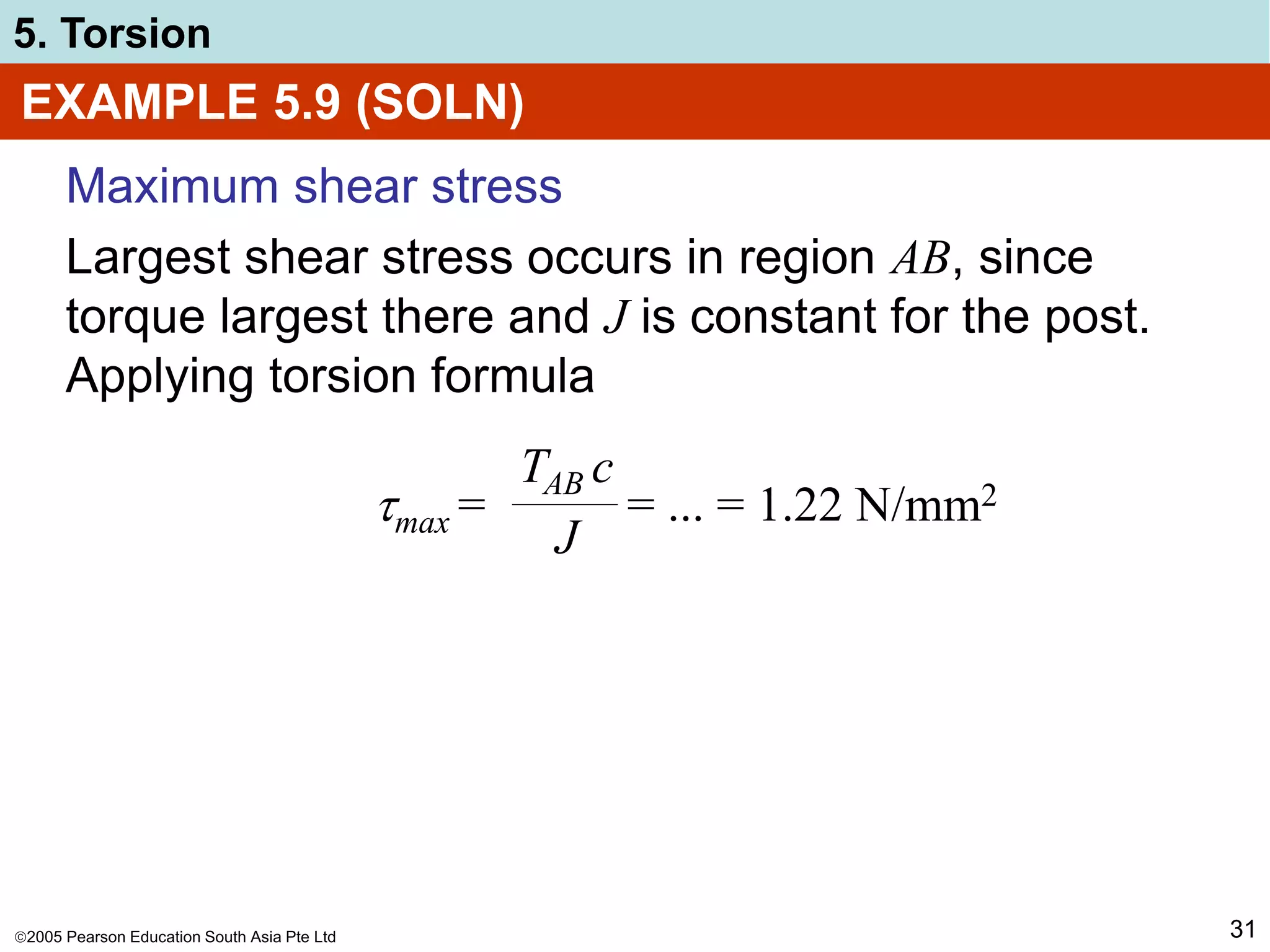
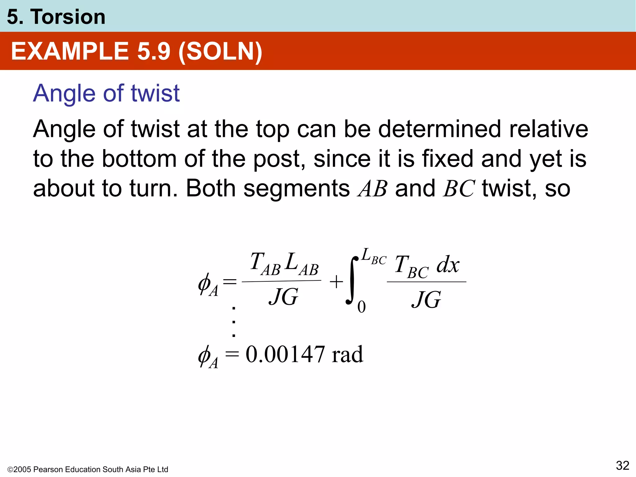
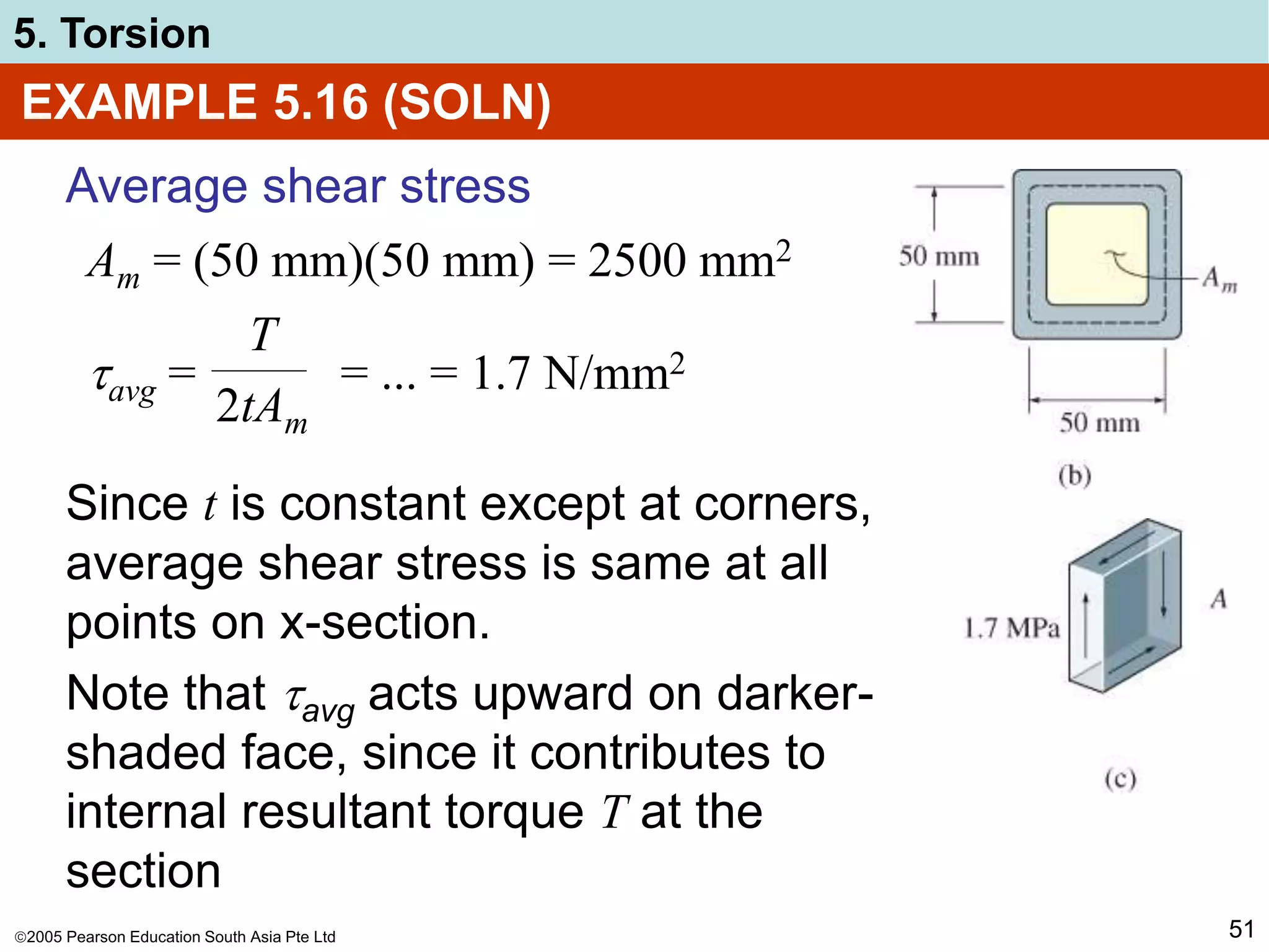
EXAMPLE 5.16 (SOLN)
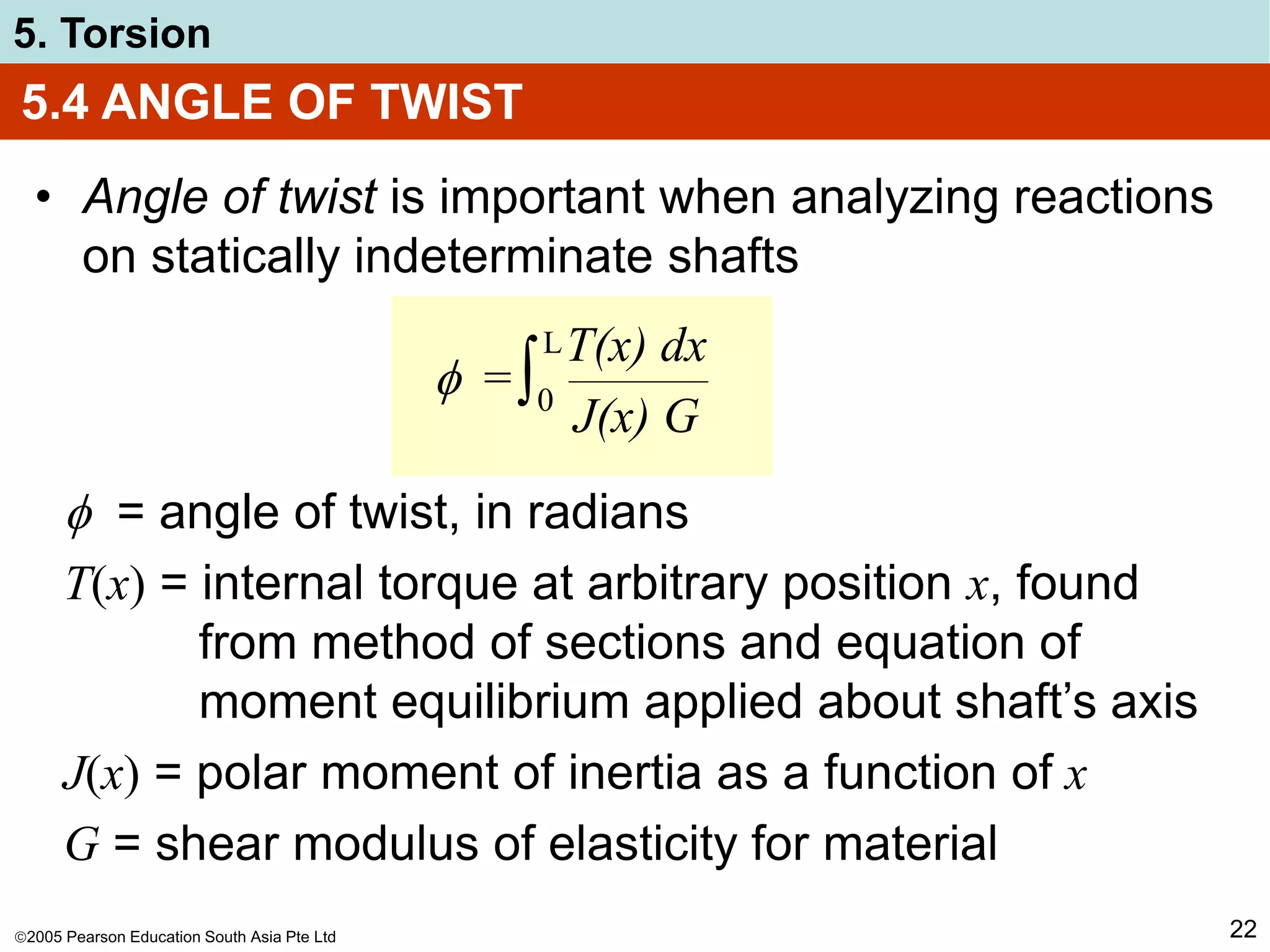
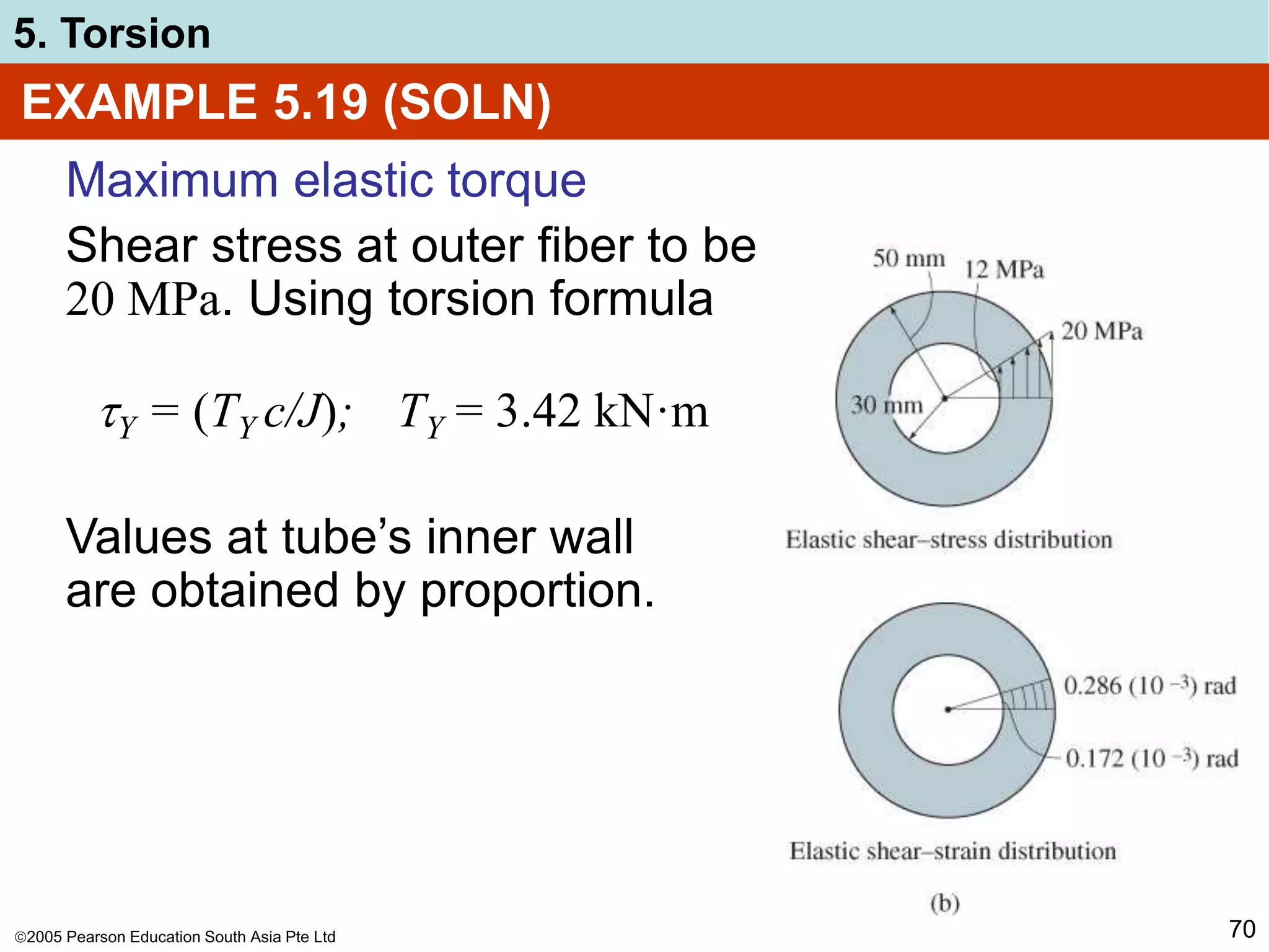
Angle of twist
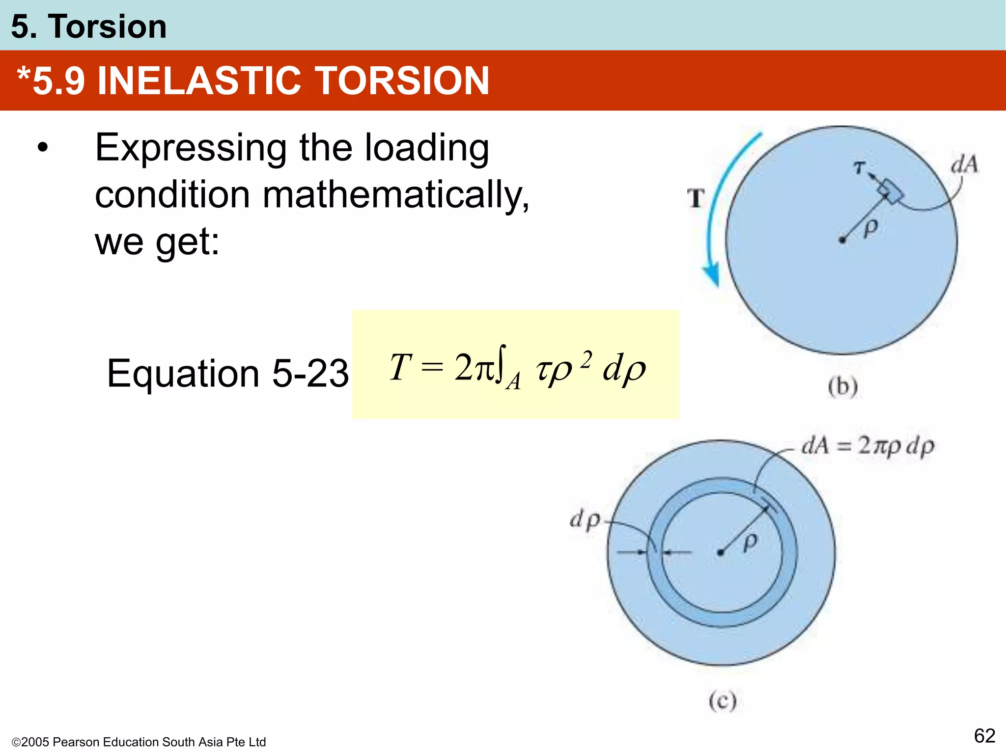
Here, integral represents length around
centerline boundary of tube, thus
= ∫
TL
4Am
2G
ds
t
O = ... = 0.196(10-4) mm-1 ∫ ds
O
= 0.196(10-4) mm-1[4(50 mm)] = 3.92 (10-3) rad](https://image.slidesharecdn.com/mak205chapter5-221216082628-d15dba4b/75/MAK205_Chapter5-ppt-52-2048.jpg)


![MTORSION [EngineeringDuniya.co MTORSION [EngineeringDuniya.com].pptm].ppt](https://cdn.slidesharecdn.com/ss_thumbnails/mtorsionengineeringduniya-241112074730-b7e902c3-thumbnail.jpg?width=640&height=640&fit=bounds)


