Downloaded 77 times
![Exp No: Date:
DESIGN OF SIMPLE BEAM USING STAAD.PRO
AIM
To design a simple beam using STAAD.Pro
SOFTWARE USED
STAAD.Pro
PROCEDURE:
1) STARTING THE PROGRAM
1. Start STAAD.Pro by double clicking on the icon
2. Click New Project Tick “ Space” Add ‘File Name’ and choose location
Change Length Units to “Meter” and Force units “Kilo Newton” Click ‘Next’.
3. Tick “ Add Beam” Click ‘Finish’.
2) GENERATING THE MODEL GEOMETRY
4. Click on to View from +Z. [Can consider it as the Front view]
5. Draw the beam length using Snap Node.
3) SPECIFY MEMBER PROPERTIES
6. From the file menu go to
Commands Member property Prismatic Rectangle
YD = 0.45 m
ZD = 0.23 m
Click, Add Close
Click, Assign to view Assign Close
(Click ‘Yes’ when prompted to continue.)
4) SPECIFY SUPPORT TYPES
7. Commands Support specifications Fixed Click Add](https://image.slidesharecdn.com/exp11designofsimplebeamusingstaadpro-170708122403/85/Design-of-simple-beam-using-staad-pro-doc-file-1-320.jpg)
![Exp No: Date:
DESIGN OF SIMPLE BEAM USING STAAD.PRO
AIM
To design a simple beam using STAAD.Pro
SOFTWARE USED
STAAD.Pro
PROCEDURE:
1) STARTING THE PROGRAM
1. Start STAAD.Pro by double clicking on the icon
2. Click New Project Tick “ Space” Add ‘File Name’ and choose location
Change Length Units to “Meter” and Force units “Kilo Newton” Click ‘Next’.
3. Tick “ Add Beam” Click ‘Finish’.
2) GENERATING THE MODEL GEOMETRY
4. Click on to View from +Z. [Can consider it as the Front view]
5. Draw the beam length using Snap Node.
3) SPECIFY MEMBER PROPERTIES
6. From the file menu go to
Commands Member property Prismatic Rectangle
YD = 0.45 m
ZD = 0.23 m
Click, Add Close
Click, Assign to view Assign Close
(Click ‘Yes’ when prompted to continue.)
4) SPECIFY SUPPORT TYPES
7. Commands Support specifications Fixed Click Add](https://image.slidesharecdn.com/exp11designofsimplebeamusingstaadpro-170708122403/75/Design-of-simple-beam-using-staad-pro-doc-file-1-2048.jpg)
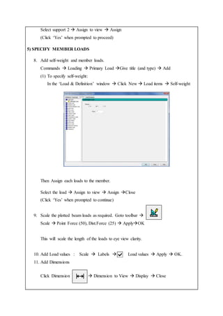
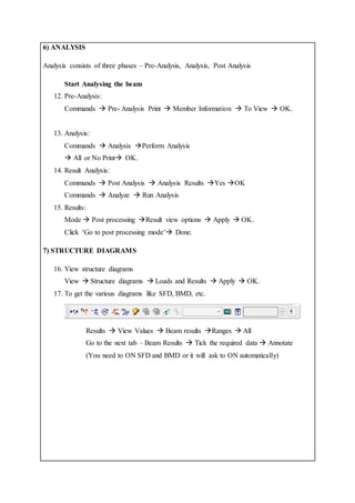
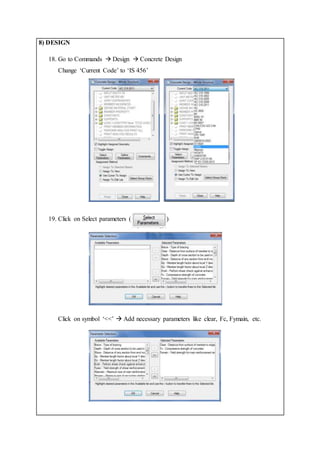
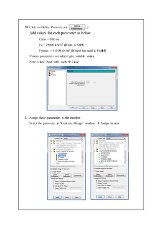
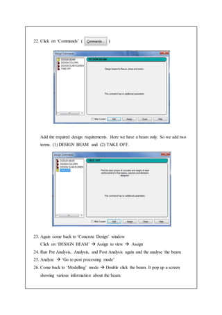
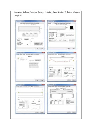
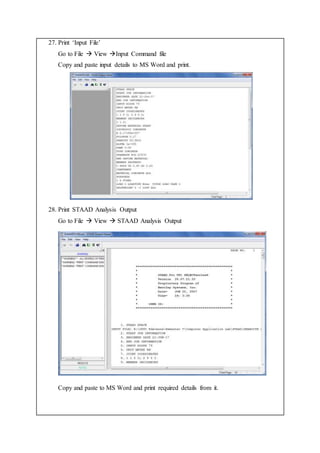
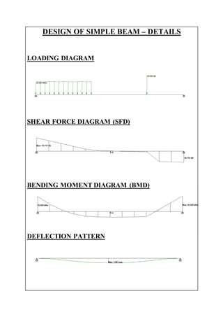
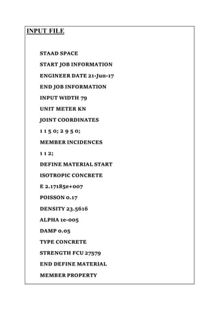
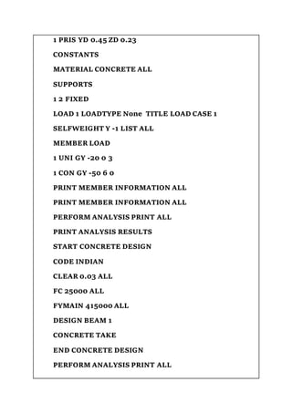
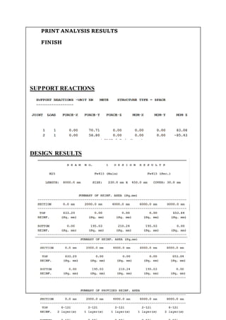
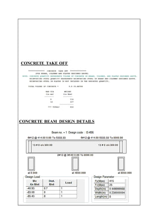


The document describes designing a simple beam using STAAD.Pro software. It involves generating the beam geometry, applying loads and supports, analyzing the beam, and reviewing the results, which include the loading diagram, shear force diagram, bending moment diagram, deflection pattern, input file, concrete takeoff, and concrete design details. The key steps are 1) creating the beam model in STAAD.Pro, 2) applying the loading and support conditions, 3) analyzing the beam, and 4) reviewing the output results.