Downloaded 637 times
![Shear stress variation across a few standard cross sections
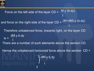
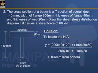
1. Rectangular section:
Consider a rectangular section
of width b and depth d
subjected to shearing force F.
Let AA be a fibre at a distance
y from the neutral axis as
shown in fig.
From the equation for shear
stress :
τ = F a y
I b
where : a = b[d
2
y]](https://image.slidesharecdn.com/shearstressesinbeams-180511185408/85/Shear-stresses-in-beams-7-320.jpg)
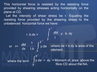
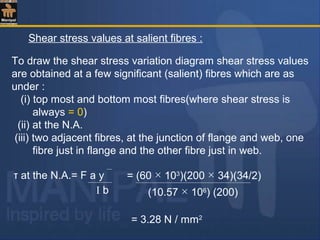
![substituting,
and I = bd3
/12
y = y + 1/2
d
2
y[ ]
( bd3
/ 12) . b
τ =
F. b
d
2
y[ ]. 1/2
d
2
y+[ ]
1/2
d
2
y+[ ]=
−=
+×
−
= 2
2
33
4
622
6
y
d
bd
F
bd
y
d
y
d
F
222
1
222
1 ydyd
y +
=−
+=
−= 2
2
3
4
6
y
d
bd
F
ι](https://image.slidesharecdn.com/shearstressesinbeams-180511185408/85/Shear-stresses-in-beams-8-320.jpg)
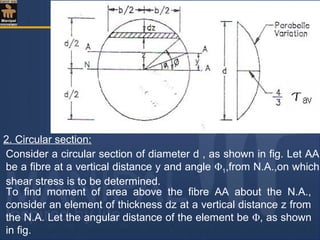
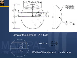
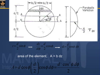
![Moment of area of the element about the N.A.= area× z
Therefore moment of the entire area ,above the fibre AA,
about the N.A.= a y
φφφ
φφφ
d
d
d
d
d
sincos
4
sin
2
cos
2
2
3
2
2
=
=
φφφ
π
φ
d
d
sincos
4
2
2/
1
3
∫=
if cosø = t , dt/dø = - sin ø , dt = - sin ø dø and –t3
/3 is integration
= d3
[-cos3
]
2
π
1
4
ø
ø3 ]cos[
12
]cos
2
cos[
12
1
3
3
1
33
3
φ
φ
π
d
d
=
+−=](https://image.slidesharecdn.com/shearstressesinbeams-180511185408/85/Shear-stresses-in-beams-13-320.jpg)
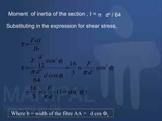
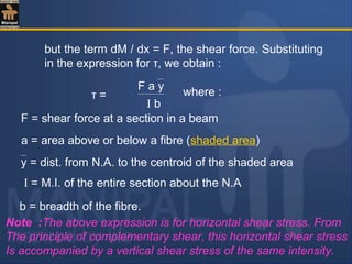
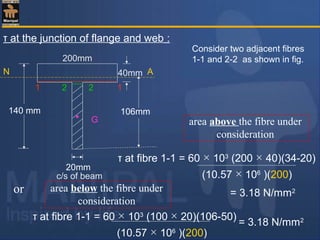
![16 F [1 – ( ) ]
3 πd2
y
d / 2
2
=
Hence shear stress varies parabolically over the depth.
Its value is zero at the extreme fibres where y = d / 2 and its
value is maximum when y = 0 (at the N.A.) and is given by :
τmax = 16 F3 πd2
4 F
=
3 πd2
/ 4
= 4 F
3 A
F = Shear Force
A Area of cross section
= Average shear stress
Thus in circular sections shear stress is maximum at the centre,
and is equal to 4 / 3 times the average shear stress.](https://image.slidesharecdn.com/shearstressesinbeams-180511185408/85/Shear-stresses-in-beams-15-320.jpg)
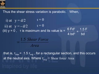
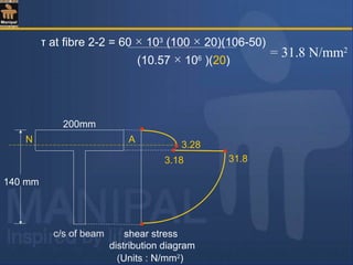
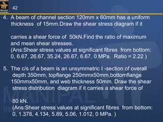
![To find M.I. of the section about the N.A.
I = I NA (1) + I NA (2)
200mm
20mm
140 mm
40mmN A
106mm
34mmG1
G2
(1)
(2)
=[ (200 x 403
) /12 + (200 × 40)(34-20)2
]
+ [20 × 1003
/ 12 +(20 × 100)(106-50)2
]
= 10.57 × 10⁶
mm4
22
100 mm](https://image.slidesharecdn.com/shearstressesinbeams-180511185408/85/Shear-stresses-in-beams-25-320.jpg)
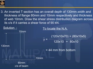
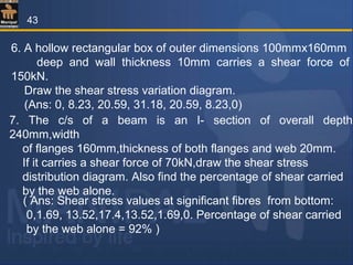
![To find M.I. of the section about the N.A.
130mm
10mm
10mm
80mm
N A
44mm
86mm
(1)
G1
(2) G2
I = I NA (1) + I NA (2) = [ (10 x1203
) /12 + (10 x 120)(86-60)2
]
[(80 × 103
) / 12 +(80 × 10)(44-5)2
]+
= 3.475 × 10⁶
mm4](https://image.slidesharecdn.com/shearstressesinbeams-180511185408/85/Shear-stresses-in-beams-30-320.jpg)
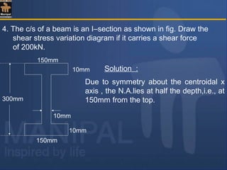
![To find M.I. of the section about the N.A.
I = I NA (1) + I NA (2) + I NA (3)
= 2 I NA (1) + I NA (2)
10mm
10mm
300mm
150mm
150mm
10mm
AN
G1
G2
G3
(1)
(2)
(3)
= 2[ 150 × 103
/12 + 150 × 10(145)2
]
+ [ 10 × 2803
/12 ]
= 81.39 × 10⁶
mm4
140 mm](https://image.slidesharecdn.com/shearstressesinbeams-180511185408/85/Shear-stresses-in-beams-34-320.jpg)
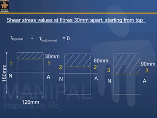
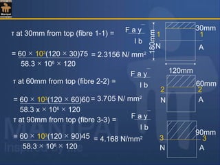
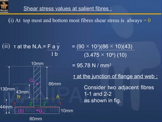
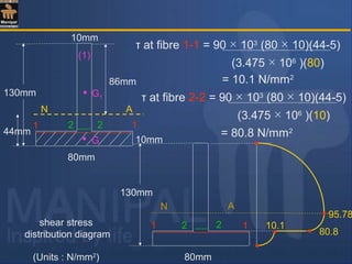
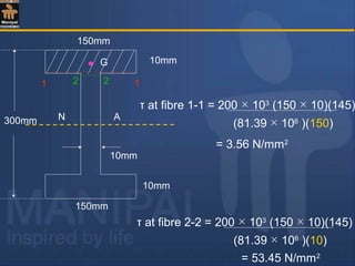
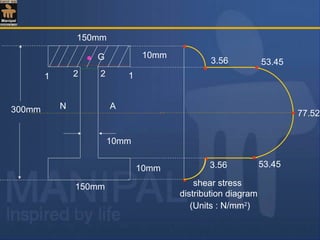
![Shear stress values at salient fibres :
= 200 × 103
[(150 × 10)145 + (140 × 10)70 ]
81.39 × 10⁶
(10)
= 77.52 N/mm2
τ at the junction of flange and web :
Consider two adjacent fibres 1-1 and 2-2 as shown in fig.
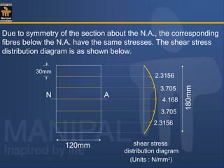
Due to symmetry of the section about the N.A., the shear stress
variation diagram also is symmetric with corresponding fibres on
either sides of the N.A.carrying the same shear stress.
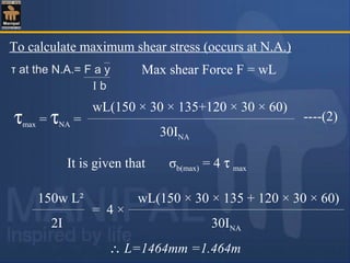
τ at the N.A.= F a y
I b
(i) At top most and bottom most fibres shear stress is always = 0](https://image.slidesharecdn.com/shearstressesinbeams-180511185408/85/Shear-stresses-in-beams-35-320.jpg)
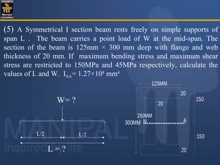
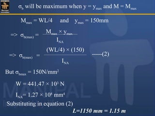
![To calculate maximum shear stress
Maximum Shear force F = W/2τ at the N.A.= F a y
I b
W [(125×20×140) + (20×130×65)]
(2 × 20 ×INA)
τmax = --------(1)
But τmax = 45N/mm2
, INA=1.27 ×10⁸
mm4
Substituting in equation(1), W=441.47×10³
N = 441.47 kN
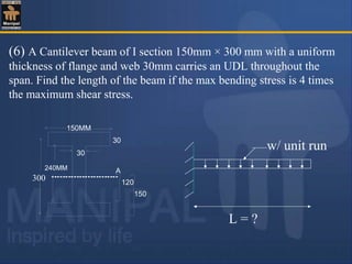
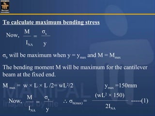
To calculate maximum bending stress
M
INA
=
σь
y
Now,](https://image.slidesharecdn.com/shearstressesinbeams-180511185408/85/Shear-stresses-in-beams-39-320.jpg)

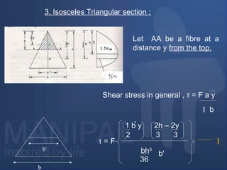
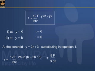
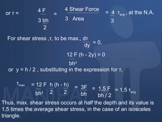
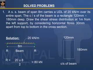
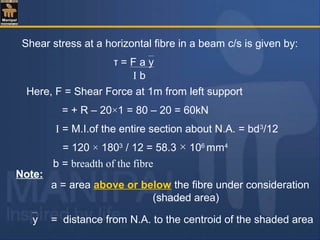
The document discusses shear stresses in beams. It defines shear stress as being due to shear force and perpendicular to the cross-sectional area. Shear stress is derived as τ = F/A, where F is the shear force and A is the cross-sectional area. Shear stress varies across standard beam cross sections like rectangular, circular, and triangular. Shear stress is maximum at the neutral axis for rectangular and circular beams, and at half the depth for triangular beams. Sample problems are included to demonstrate calculating and graphing the variation of shear stress across specific beam cross sections.