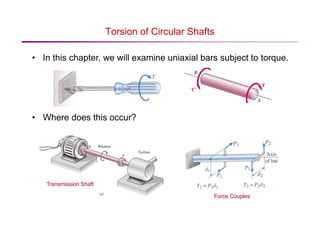
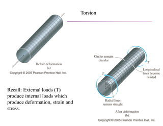
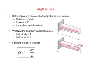
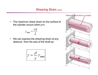
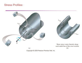
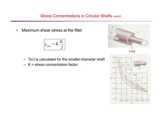
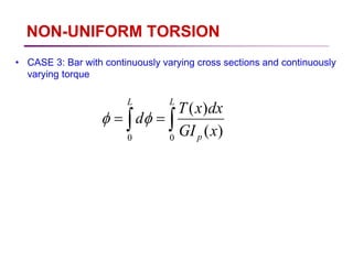
SlideShare a Scribd company logo
1 of 52
Download to read offline
Torsion
The logic of the Mechanics of Materials
Torsion
Chapter 5 – Torsion
Torsional failures
(ductile, buckling,
buckling):
Bars subjected to Torsion
Let us now consider a straight bar
supported at one end and acted upon by
two pairs of equal and opposite forces.
Then each pair of forces and form a
couple that tend to twist the bar about its
longitudinal axis, thus producing surface
tractions and moments.
Then we can write the moments as
1
P 2
P
1 1 1
T P d
= 2 2 2
T P d
=
Torsion of Circular Shafts
• In this chapter, we will examine uniaxial bars subject to torque.
• Where does this occur?
Transmission Shaft
Force Couples
Torsion
Recall: External loads (T)
produce internal loads which
produce deformation, strain and
stress.
Torsion of Circular Shafts cont’d
• We assume
– Bar is in pure torsion
– Small rotations (the length and radius will not change)
• How does the bar deform?
– Cross-section of the bar remains the same shape, bar is simply rotating.
– Cross-section remains perpendicular to axis of cylinder (cylinder does
not warp). Not true for most
non-circular bars
Chapter 5: Torsion
Torsional Deformation of a Circular Shaft
Torque is a moment that twists a member about its
longitudinal axis.
If the angle of rotation is small, the length of the shaft
and its radius will remain unchanged.
’
Angle of Twist
• Deformation of a circular shaft subjected to pure torsion
– Fix left end of shaft
– A moves to A
– φ = angle of twist (in radians)
• What are the boundary conditions on φ ? x
– φ (x) = 0 at x = 0
– φ (x) = φ at x = L
• For pure torsion, φ is linear.
Shearing Strain
• Calculate the surface shear strain in the
cylinder.
• Consider an element of length dx.
• Recall we assume small φ & small γ.
dx
• This equation applies to any function φ (x).
• For pure torsion φ (x) = φ x / L, so
C’ C
Shearing Strain cont’d
Maximum shear strain on surface
• The maximum shear strain on the surface of
the cylinder occurs when ρ=c.
• We can express the shearing strain at any
distance from the axis of the shaft as
The Torsion Formula
When material is linear-elastic, Hooke’s law applies.
A linear variation in shear strain leads to a
corresponding linear variation in shear stress
along any radial line on the cross section.
The Torsion Formula
If the shaft has a solid circular cross section,
If a shaft has a tubular cross section,
Shear stress profile – YOU MUST
UNDERSTAND THIS!!!!
Where is shear stress max?
zero? How does it vary
along the length and
circumference?
Stress Profiles:
Stress Profiles:
Shearing Strain cont’d
• We can also apply the equation for maximum
surface shear strain to a hollow circular tube.
c
c
• This applies for all types of materials: elastic, linear, non-
linear, plastic, etc.
Elastic Shearing Stress
• Calculate shear stress in a bar made of linearly elastic material.
• Recall Hooke’s Law for shearing stress: τ=Gγ
Torque
• We still need to relate τto the applied torque T, which is generally
the known, applied load.
• First, find the resultant moment acting on a cross-section and set this
equal to T.
c
Torque cont’d
• Continuing from previous slide:
– Where J is the polar moment of inertia of the cross section of the bar
• Plug this into the equation for τmax.
Torque cont’d
• For a non-uniform bar
φ = ∑φ = ∑Ti Li
n n
i
• For a continuously varying bar
=1 G J
i=1 i i i
Inclined Plane
• Cut a rectangular element along the plane at an angle θ.
Inclined Plane cont’d
y x
Inclined Plane cont’d
τmax occurs at θ = 0º, ±90º
• σmax occurs at θ = ±45º
τmax = σmax
• When σθ is max, τθ = 0, and when τθ is max, σθ =0.
Transmission Shafts
• In a transmission, a circular shaft transmits mechanical power from
one device to another.
Generator
– ω = angular speed of rotation of the shaft
– The shaft applies a torque T to another device
– To satisfy equilibrium the other device applies torque T to the shaft.
– The power transmitted by the shaft is
Turbine
Transmission Shafts cont’d
• Units for P=Tω
– ω = rad/s
– T = N·m (SI)
– T = ft·lb (English)
– P = Watts (1 W = 1 N·m/s) (SI)
– P = ft·lb/s (1 horsepower = hp = 550 ft·lb/s) (English)
• We can also express power in terms of frequency.
Stress Concentrations in Circular Shafts
• Up to now, we assumed that transmission shafts are loaded at the
ends through solidly attached, rigid end plates.
• In practice, torques are applied through flange couplings and fitted
keyways, which produce high stress concentrations.
Fitted keyway
Flange coupling
• One way to reduce stress concentrations is through the use of a
fillet.
Stress Concentrations in Circular Shafts cont’d
• Maximum shear stress at the fillet
Fillet
– Tc/J is calculated for the smaller-diameter shaft
– K = stress concentration factor
J
= K
Tc
max
τ
Στρέψη – περιορισμοί για άξονες
κυκλικής διατομής
• Το μήκος του μέλους που υπόκειται σε στρέψη είναι σημαντικά
μεγαλύτερο από τη μεγαλύτερη διάσταση της διατομής.
• Η περιοχή που εξετάζεται δεν περιέχει συγκεντρώσεις τάσεων.
• Η μεταβολή της εξωτερικής στρέψης ή η μεταβολή των εμβαδών των
διατομών είναι βαθμιαία, με εξαίρεση τις περιοχές συγκέντρωσης
τάσεων.
• ΟΙ εξωτερικές στρεπτικές ροπές δεν εξαρτώνται από το χρόνο, το
πρόβλημα είναι στατικό.
• Η διατομή είναι κυκλική, επιτρέποντας τη χρήση της συμμετρίας ως
προς τον άξονα για τη μείωση της παραμόρφωσης.
Στρέψη - Παραδοχές
1. Τα επίπεδα τμήματα που είναι κάθετα στον άξονα περιστροφής
παραμένουν επίπεδα κατά τη διάρκεια της παραμόρφωσης.
2. Σε μια διατομή, όλες οι ακτινικές γραμμές περιστρέφονται κατά ίσες
γωνίες κατά τη διάρκεια της παραμόρφωσης.
3. Οι ακτινικές γραμμές παραμένουν ευθείες κατά τη διάρκεια της
παραμόρφωσης.
4. Οι παραμορφώσεις είναι μικρές.
5. Το υλικό είναι γραμμικά ελαστικό.
6. Το υλικό είναι ισότροπο.
7. Το υλικό είναι ομογενές κατά μήκος της περιοχής της διατομής.
ΠΑΡΑΔΟΧΕΣ
• Το υλικό είναι ομογενές μεταξύ x1 και x2 (G=σταθερό)
• Ο άξονας δεν λαμβάνει κωνοειδές σχήμα (J =σταθερή)
• Η εξωτερική (και επομένως και η εσωτερική) στρέψη δεν
μεταβάλλεται με το x μεταξύ x1 και x2 (T = σταθερό)
NON-UNIFORM TORSION
• Uniform/Pure torsion – torsion of prismatic bar subjected to torques
acting only at the ends
• Non-uniform torsion– the bar need not be prismatic and the applied
torque may act anywhere along the axis of bar
• Non-uniform torsion can be analysed by
– Applying formula of pure torsion to finite segments of the bar then adding
the results
– Applying formula to differential elements of the bar and then integrating
NON-UNIFORM TORSION
∑
∑ =
=
=
=
n
i i
p
i
i
i
n
i
i
I
G
L
T
1
1 )
(
φ
φ
• CASE 1: Bar consisting of prismatic segments with constant torque
throughout each segment
• CASE 2: Bar with continuously varying cross sections and constant
torque
∫
∫ =
=
L
p
L
x
GI
Tdx
d
0
0
)
(
φ
φ
NON-UNIFORM TORSION
• CASE 3: Bar with continuously varying cross sections and continuously
varying torque
∫
∫ =
=
L
p
L
x
GI
dx
x
T
d
0
0
)
(
)
(
φ
φ
NON-UNIFORM TORSION
• Limitations
– Analyses described valid for bar made of linearly elastic materials
– Circular cross sections (Solid /hollow)
• Stresses determined from the torsion formula valid in region of
the bar away from stress concentrations (diameter changes
abruptly/concentrated torque applied
– For the case above, Angle of twist still valid
– Changes in diameter is are small and gradually (angle of taper max 10o)
SOLID NON-CIRCULAR SHAFTS
Solid Noncircular Shafts
The maximum shear stress and the angle of twist for solid
noncircular shafts are tabulated as below:
Comparison of Axial and Torsion formulae.
AE =Axial rigidity
Axial Stiffness
Axial Flexibilty:
GJ =Torsional rigidity
Torsional
Stiffness
Torsional Flexibilty:
L
AE
kA =
1
−
= A
A k
f
L
GJ
kT =
1
−
= T
T k
f
Axial displacement
∑
=
i i
i
i
i
G
J
L
T
φ
∑
=
i i
i
i
i
E
A
L
P
δ
Torsional displacement
Axial stress
A
P
=
σ
J
Tρ
τ =
Torsional stress
Sample Problem 1
Shaft BC is hollow with inner and outer
diameters of 90 mm and 120 mm,
respectively. Shafts AB and CD are solid
and of diameter d. For the loading shown,
determine (a) the minimum and maximum
shearing stress in shaft BC, (b) the
required diameter d of shafts AB and CD
if the allowable shearing stress in these
shafts is 65 MPa.
SOLUTION:
Cut sections through shafts AB and
BC and perform static equilibrium
analyses to find torque loadings.
Given allowable shearing stress and
applied torque, invert the elastic
torsion formula to find the
required diameter.
Apply elastic torsion formulas to
find minimum and maximum
stress on shaft BC.
Sample Problem 1
SOLUTION:
Cut sections through shafts AB and BC
and perform static equilibrium analysis
to find torque loadings.
( )
CD
AB
AB
x
T
T
T
M
=
⋅
=
−
⋅
=
=
∑
m
kN
6
m
kN
6
0 ( ) ( )
m
kN
20
m
kN
14
m
kN
6
0
⋅
=
−
⋅
+
⋅
=
=
∑
BC
BC
x
T
T
M
Fig. 1 Free-body diagram for section between A and B. Fig. 2 Free-body diagram for section between B and C.
Sample Problem 1
Apply elastic torsion formulas to
find minimum and maximum
stress on shaft BC.
( ) ( ) ( )
[ ]
4
6
4
4
4
1
4
2
m
10
92
.
13
045
.
0
060
.
0
2
2
−
×
=
−
=
−
=
π
π
c
c
J
( )( )
MPa
2
.
86
m
10
92
.
13
m
060
.
0
m
kN
20
4
6
2
2
max
=
×
⋅
=
=
= −
J
c
TBC
τ
τ
MPa
7
.
64
mm
60
mm
45
MPa
2
.
86
min
min
2
1
max
min
=
=
=
τ
τ
τ
τ
c
c
MPa
7
.
64
MPa
2
.
86
min
max
=
=
τ
τ
Given allowable shearing stress and
applied torque, invert the elastic torsion
formula to find the required diameter.
m
10
9
.
38
m
kN
6
65
3
3
2
4
2
max
−
×
=
⋅
=
=
=
c
c
MPa
c
Tc
J
Tc
π
π
τ
mm
8
.
77
2 =
= c
d
Fig. 3 Shearing stress distribution on cross section. Fig. 4 Free-body diagram of shaft portion AB.
Statically Indeterminate Shafts
Given the shaft dimensions and the applied torque,
we would like to find the torque reactions at A and
B.
From a free-body analysis of the shaft,
which is not sufficient to find the end torques.
The problem is statically indeterminate.
ft
lb
90 ⋅
=
+ B
A T
T
ft
lb
90
1
2
2
1 ⋅
=
+ A
A T
J
L
J
L
T
Substitute into the original equilibrium equation,
A
B
B
A T
J
L
J
L
T
G
J
L
T
G
J
L
T
1
2
2
1
2
2
1
1
2
1 0 =
=
−
=
+
= φ
φ
φ
Divide the shaft into two components which
must have compatible deformations,
(a) Shaft with central applied torque and fixed
ends. (b) free-body diagram of shaft AB. (c)
Free-body diagrams for solid and hollow
segments.
Example 2
The tapered shaft is made of a material having a shear modulus G.
Determine the angle of twist of its end B when subjected to the torque.
Solution:
From free body diagram, the internal torque is T.
Thus, at x,
For angle of twist,
STATICALLY INDETERMINATE TORQUE-LOADED
MEMBERS
Procedure for analysis:
use both equilibrium and compatibility equations
Equilibrium
Draw a free-body diagram of the shaft in order to identify
all the torques that act on it. Then write the equations
of moment equilibrium about the axis of the shaft.
Compatibility
To write the compatibility equation, investigate the way
the shaft will twist when subjected to the external
loads, and give consideration as to how the supports
constrain the shaft when it is twisted.
STATICALLY INDETERMINATE TORQUE-LOADED
MEMBERS (cont)
Express the compatibility condition in terms of the
rotational displacements caused by the reactive
torques, and then use a torque-displacement relation,
such as Φ = TL/JG, to relate the unknown torques to
the unknown displacements.
Solve the equilibrium and compatibility equations for the
unknown reactive torques. If any of the magnitudes
have a negative numerical value, it indicates that this
torque acts in the opposite sense of direction to that
indicated on the free-body diagram.
EXAMPLE 3
The solid steel shaft shown in Fig. has a diameter of 20 mm.
If it is subjected to the two torques, determine the reactions
at the fixed supports A and B.
EXAMPLE 3 (cont)
It is seen that the problem is statically indeterminate since there is only one
available equation of equilibrium and there are 2 unknowns
Since the ends of the shaft are fixed, the angle of twist of one end of the
shaft with respect to the other must be zero.
Solution
(1)
0
500
800
0
=
−
−
+
−
=
∑
A
b
x
T
T
M
0
/ =
B
A
φ
EXAMPLE 3 (cont)
Using the sign convention established,
Using Eq. 1,
The negative sign indicates that acts
in the opposite direction of that shown
in Fig. (b)
Solution
( ) ( )( ) ( )( )
(Ans)
m
N
645
0
3
.
0
300
5
.
1
800
2
.
0
⋅
=
=
−
+
−
+
−
B
B
B
B
T
JG
T
JG
T
JG
T
m
N
345 ⋅
−
=
A
T

More Related Content

What's hot (20)

Lec3 principle virtual_work_method
Lec3 principle virtual_work_methodLec3 principle virtual_work_method
Lec3 principle virtual_work_method
 
TORSION (MECHANICS OF SOLIDS)
TORSION (MECHANICS OF SOLIDS)TORSION (MECHANICS OF SOLIDS)
TORSION (MECHANICS OF SOLIDS)
 
J3010 Unit 3
J3010   Unit 3J3010   Unit 3
J3010 Unit 3
 
torsion
torsiontorsion
torsion
 
Fluid Mechanics
Fluid MechanicsFluid Mechanics
Fluid Mechanics
 
Impact of jet
Impact of jetImpact of jet
Impact of jet
 
Design of Riveted joints(Boiler joints)
Design of Riveted joints(Boiler joints)Design of Riveted joints(Boiler joints)
Design of Riveted joints(Boiler joints)
 
Thick cylinders
Thick cylindersThick cylinders
Thick cylinders
 
Unit 2 stresses in composite sections
Unit 2  stresses in composite sectionsUnit 2  stresses in composite sections
Unit 2 stresses in composite sections
 
Bending stresses in beams
Bending stresses in beams Bending stresses in beams
Bending stresses in beams
 
Finite Element analysis of Spring Assembly
Finite Element analysis of Spring AssemblyFinite Element analysis of Spring Assembly
Finite Element analysis of Spring Assembly
 
Unit 2 design of shaft
Unit 2 design of shaftUnit 2 design of shaft
Unit 2 design of shaft
 
Static Force Analysis
Static Force AnalysisStatic Force Analysis
Static Force Analysis
 
Enigne forces analysis
Enigne forces analysis Enigne forces analysis
Enigne forces analysis
 
Columns analysis
Columns analysisColumns analysis
Columns analysis
 
Chapter 4: Torsion
Chapter 4: TorsionChapter 4: Torsion
Chapter 4: Torsion
 
Types of stresses and theories of failure (machine design & industrial drafti...
Types of stresses and theories of failure (machine design & industrial drafti...Types of stresses and theories of failure (machine design & industrial drafti...
Types of stresses and theories of failure (machine design & industrial drafti...
 
Clutches
ClutchesClutches
Clutches
 
Fluid ans t_2
Fluid ans t_2Fluid ans t_2
Fluid ans t_2
 
Analysis of structures
Analysis of structuresAnalysis of structures
Analysis of structures
 

Similar to Torsion_2.pdf

Tutorial_Aerospace_structures_torsion.pptx
Tutorial_Aerospace_structures_torsion.pptxTutorial_Aerospace_structures_torsion.pptx
Tutorial_Aerospace_structures_torsion.pptxAwwalDami
 
Torsion of circular shafts
Torsion of circular shaftsTorsion of circular shafts
Torsion of circular shaftsMayur Ekhande
 
Lecture 1 Single Mode Loading Part A.doc
Lecture 1 Single Mode Loading Part A.docLecture 1 Single Mode Loading Part A.doc
Lecture 1 Single Mode Loading Part A.docDylanONeill11
 
Torsion of circular shafts
Torsion of circular shaftsTorsion of circular shafts
Torsion of circular shaftsYatin Singh
 
Torsional Stress
Torsional StressTorsional Stress
Torsional Stresslimon1705
 
Torsional and bending stresses in machine parts
Torsional and bending stresses in machine partsTorsional and bending stresses in machine parts
Torsional and bending stresses in machine partsMohamed Mohamed El-Sayed
 
Unit 2 Shafts and Coupling.pptx
Unit 2 Shafts and Coupling.pptxUnit 2 Shafts and Coupling.pptx
Unit 2 Shafts and Coupling.pptxCharunnath S V
 
Torsion-mmmmm-84739392727363638393999909
Torsion-mmmmm-84739392727363638393999909Torsion-mmmmm-84739392727363638393999909
Torsion-mmmmm-84739392727363638393999909elladanicaj
 
Design of helical spring
Design of helical springDesign of helical spring
Design of helical springKunj Thummar
 
Lecture-6 (Flexural Formula).pptx
Lecture-6 (Flexural Formula).pptxLecture-6 (Flexural Formula).pptx
Lecture-6 (Flexural Formula).pptxMbaloch5
 

Similar to Torsion_2.pdf (20)

Kuliah torsion
Kuliah torsionKuliah torsion
Kuliah torsion
 
chapter3_Shaft.ppt
chapter3_Shaft.pptchapter3_Shaft.ppt
chapter3_Shaft.ppt
 
Tutorial_Aerospace_structures_torsion.pptx
Tutorial_Aerospace_structures_torsion.pptxTutorial_Aerospace_structures_torsion.pptx
Tutorial_Aerospace_structures_torsion.pptx
 
Chapter 03.pdf
Chapter 03.pdfChapter 03.pdf
Chapter 03.pdf
 
Torsion of circular shafts
Torsion of circular shaftsTorsion of circular shafts
Torsion of circular shafts
 
01_Introducción vigas.pptx
01_Introducción vigas.pptx01_Introducción vigas.pptx
01_Introducción vigas.pptx
 
Lecture 1 Single Mode Loading Part A.doc
Lecture 1 Single Mode Loading Part A.docLecture 1 Single Mode Loading Part A.doc
Lecture 1 Single Mode Loading Part A.doc
 
Torsion of circular shafts
Torsion of circular shaftsTorsion of circular shafts
Torsion of circular shafts
 
13881154.ppt
13881154.ppt13881154.ppt
13881154.ppt
 
Design of.pptx
Design of.pptxDesign of.pptx
Design of.pptx
 
Torsional Stress
Torsional StressTorsional Stress
Torsional Stress
 
Bending stresses in beams
Bending stresses in beamsBending stresses in beams
Bending stresses in beams
 
Torsional and bending stresses in machine parts
Torsional and bending stresses in machine partsTorsional and bending stresses in machine parts
Torsional and bending stresses in machine parts
 
Unit 2 Shafts and Coupling.pptx
Unit 2 Shafts and Coupling.pptxUnit 2 Shafts and Coupling.pptx
Unit 2 Shafts and Coupling.pptx
 
Torsion-mmmmm-84739392727363638393999909
Torsion-mmmmm-84739392727363638393999909Torsion-mmmmm-84739392727363638393999909
Torsion-mmmmm-84739392727363638393999909
 
Design of helical spring
Design of helical springDesign of helical spring
Design of helical spring
 
MAK205_Chapter5.ppt
MAK205_Chapter5.pptMAK205_Chapter5.ppt
MAK205_Chapter5.ppt
 
Torsión gauddy
Torsión gauddyTorsión gauddy
Torsión gauddy
 
Plastic bottle analysis
Plastic bottle analysisPlastic bottle analysis
Plastic bottle analysis
 
Lecture-6 (Flexural Formula).pptx
Lecture-6 (Flexural Formula).pptxLecture-6 (Flexural Formula).pptx
Lecture-6 (Flexural Formula).pptx
 

Recently uploaded

Decoding Kotlin - Your guide to solving the mysterious in Kotlin.pptx
Decoding Kotlin - Your guide to solving the mysterious in Kotlin.pptxDecoding Kotlin - Your guide to solving the mysterious in Kotlin.pptx
Decoding Kotlin - Your guide to solving the mysterious in Kotlin.pptxJoão Esperancinha
 
MANUFACTURING PROCESS-II UNIT-2 LATHE MACHINE
MANUFACTURING PROCESS-II UNIT-2 LATHE MACHINEMANUFACTURING PROCESS-II UNIT-2 LATHE MACHINE
MANUFACTURING PROCESS-II UNIT-2 LATHE MACHINESIVASHANKAR N
 
Sheet Pile Wall Design and Construction: A Practical Guide for Civil Engineer...
Sheet Pile Wall Design and Construction: A Practical Guide for Civil Engineer...Sheet Pile Wall Design and Construction: A Practical Guide for Civil Engineer...
Sheet Pile Wall Design and Construction: A Practical Guide for Civil Engineer...Dr.Costas Sachpazis
 
Software Development Life Cycle By Team Orange (Dept. of Pharmacy)
Software Development Life Cycle By  Team Orange (Dept. of Pharmacy)Software Development Life Cycle By  Team Orange (Dept. of Pharmacy)
Software Development Life Cycle By Team Orange (Dept. of Pharmacy)Suman Mia
 
Analog to Digital and Digital to Analog Converter
Analog to Digital and Digital to Analog ConverterAnalog to Digital and Digital to Analog Converter
Analog to Digital and Digital to Analog ConverterAbhinavSharma374939
 
Call Girls in Nagpur Suman Call 7001035870 Meet With Nagpur Escorts
Call Girls in Nagpur Suman Call 7001035870 Meet With Nagpur EscortsCall Girls in Nagpur Suman Call 7001035870 Meet With Nagpur Escorts
Call Girls in Nagpur Suman Call 7001035870 Meet With Nagpur EscortsCall Girls in Nagpur High Profile
 
(RIA) Call Girls Bhosari ( 7001035870 ) HI-Fi Pune Escorts Service
(RIA) Call Girls Bhosari ( 7001035870 ) HI-Fi Pune Escorts Service(RIA) Call Girls Bhosari ( 7001035870 ) HI-Fi Pune Escorts Service
(RIA) Call Girls Bhosari ( 7001035870 ) HI-Fi Pune Escorts Serviceranjana rawat
 
College Call Girls Nashik Nehal 7001305949 Independent Escort Service Nashik
College Call Girls Nashik Nehal 7001305949 Independent Escort Service NashikCollege Call Girls Nashik Nehal 7001305949 Independent Escort Service Nashik
College Call Girls Nashik Nehal 7001305949 Independent Escort Service NashikCall Girls in Nagpur High Profile
 
Porous Ceramics seminar and technical writing
Porous Ceramics seminar and technical writingPorous Ceramics seminar and technical writing
Porous Ceramics seminar and technical writingrakeshbaidya232001
 
High Profile Call Girls Nagpur Isha Call 7001035870 Meet With Nagpur Escorts
High Profile Call Girls Nagpur Isha Call 7001035870 Meet With Nagpur EscortsHigh Profile Call Girls Nagpur Isha Call 7001035870 Meet With Nagpur Escorts
High Profile Call Girls Nagpur Isha Call 7001035870 Meet With Nagpur Escortsranjana rawat
 
OSVC_Meta-Data based Simulation Automation to overcome Verification Challenge...
OSVC_Meta-Data based Simulation Automation to overcome Verification Challenge...OSVC_Meta-Data based Simulation Automation to overcome Verification Challenge...
OSVC_Meta-Data based Simulation Automation to overcome Verification Challenge...Soham Mondal
 
Call Girls Delhi {Jodhpur} 9711199012 high profile service
Call Girls Delhi {Jodhpur} 9711199012 high profile serviceCall Girls Delhi {Jodhpur} 9711199012 high profile service
Call Girls Delhi {Jodhpur} 9711199012 high profile servicerehmti665
 
VIP Call Girls Service Hitech City Hyderabad Call +91-8250192130
VIP Call Girls Service Hitech City Hyderabad Call +91-8250192130VIP Call Girls Service Hitech City Hyderabad Call +91-8250192130
VIP Call Girls Service Hitech City Hyderabad Call +91-8250192130Suhani Kapoor
 
What are the advantages and disadvantages of membrane structures.pptx
What are the advantages and disadvantages of membrane structures.pptxWhat are the advantages and disadvantages of membrane structures.pptx
What are the advantages and disadvantages of membrane structures.pptxwendy cai
 
main PPT.pptx of girls hostel security using rfid
main PPT.pptx of girls hostel security using rfidmain PPT.pptx of girls hostel security using rfid
main PPT.pptx of girls hostel security using rfidNikhilNagaraju
 
Microscopic Analysis of Ceramic Materials.pptx
Microscopic Analysis of Ceramic Materials.pptxMicroscopic Analysis of Ceramic Materials.pptx
Microscopic Analysis of Ceramic Materials.pptxpurnimasatapathy1234
 
High Profile Call Girls Nagpur Meera Call 7001035870 Meet With Nagpur Escorts
High Profile Call Girls Nagpur Meera Call 7001035870 Meet With Nagpur EscortsHigh Profile Call Girls Nagpur Meera Call 7001035870 Meet With Nagpur Escorts
High Profile Call Girls Nagpur Meera Call 7001035870 Meet With Nagpur EscortsCall Girls in Nagpur High Profile
 
HARMONY IN THE NATURE AND EXISTENCE - Unit-IV
HARMONY IN THE NATURE AND EXISTENCE - Unit-IVHARMONY IN THE NATURE AND EXISTENCE - Unit-IV
HARMONY IN THE NATURE AND EXISTENCE - Unit-IVRajaP95
 

Recently uploaded (20)

Decoding Kotlin - Your guide to solving the mysterious in Kotlin.pptx
Decoding Kotlin - Your guide to solving the mysterious in Kotlin.pptxDecoding Kotlin - Your guide to solving the mysterious in Kotlin.pptx
Decoding Kotlin - Your guide to solving the mysterious in Kotlin.pptx
 
MANUFACTURING PROCESS-II UNIT-2 LATHE MACHINE
MANUFACTURING PROCESS-II UNIT-2 LATHE MACHINEMANUFACTURING PROCESS-II UNIT-2 LATHE MACHINE
MANUFACTURING PROCESS-II UNIT-2 LATHE MACHINE
 
9953056974 Call Girls In South Ex, Escorts (Delhi) NCR.pdf
9953056974 Call Girls In South Ex, Escorts (Delhi) NCR.pdf9953056974 Call Girls In South Ex, Escorts (Delhi) NCR.pdf
9953056974 Call Girls In South Ex, Escorts (Delhi) NCR.pdf
 
Sheet Pile Wall Design and Construction: A Practical Guide for Civil Engineer...
Sheet Pile Wall Design and Construction: A Practical Guide for Civil Engineer...Sheet Pile Wall Design and Construction: A Practical Guide for Civil Engineer...
Sheet Pile Wall Design and Construction: A Practical Guide for Civil Engineer...
 
Software Development Life Cycle By Team Orange (Dept. of Pharmacy)
Software Development Life Cycle By  Team Orange (Dept. of Pharmacy)Software Development Life Cycle By  Team Orange (Dept. of Pharmacy)
Software Development Life Cycle By Team Orange (Dept. of Pharmacy)
 
DJARUM4D - SLOT GACOR ONLINE | SLOT DEMO ONLINE
DJARUM4D - SLOT GACOR ONLINE | SLOT DEMO ONLINEDJARUM4D - SLOT GACOR ONLINE | SLOT DEMO ONLINE
DJARUM4D - SLOT GACOR ONLINE | SLOT DEMO ONLINE
 
Analog to Digital and Digital to Analog Converter
Analog to Digital and Digital to Analog ConverterAnalog to Digital and Digital to Analog Converter
Analog to Digital and Digital to Analog Converter
 
Call Girls in Nagpur Suman Call 7001035870 Meet With Nagpur Escorts
Call Girls in Nagpur Suman Call 7001035870 Meet With Nagpur EscortsCall Girls in Nagpur Suman Call 7001035870 Meet With Nagpur Escorts
Call Girls in Nagpur Suman Call 7001035870 Meet With Nagpur Escorts
 
(RIA) Call Girls Bhosari ( 7001035870 ) HI-Fi Pune Escorts Service
(RIA) Call Girls Bhosari ( 7001035870 ) HI-Fi Pune Escorts Service(RIA) Call Girls Bhosari ( 7001035870 ) HI-Fi Pune Escorts Service
(RIA) Call Girls Bhosari ( 7001035870 ) HI-Fi Pune Escorts Service
 
College Call Girls Nashik Nehal 7001305949 Independent Escort Service Nashik
College Call Girls Nashik Nehal 7001305949 Independent Escort Service NashikCollege Call Girls Nashik Nehal 7001305949 Independent Escort Service Nashik
College Call Girls Nashik Nehal 7001305949 Independent Escort Service Nashik
 
Porous Ceramics seminar and technical writing
Porous Ceramics seminar and technical writingPorous Ceramics seminar and technical writing
Porous Ceramics seminar and technical writing
 
High Profile Call Girls Nagpur Isha Call 7001035870 Meet With Nagpur Escorts
High Profile Call Girls Nagpur Isha Call 7001035870 Meet With Nagpur EscortsHigh Profile Call Girls Nagpur Isha Call 7001035870 Meet With Nagpur Escorts
High Profile Call Girls Nagpur Isha Call 7001035870 Meet With Nagpur Escorts
 
OSVC_Meta-Data based Simulation Automation to overcome Verification Challenge...
OSVC_Meta-Data based Simulation Automation to overcome Verification Challenge...OSVC_Meta-Data based Simulation Automation to overcome Verification Challenge...
OSVC_Meta-Data based Simulation Automation to overcome Verification Challenge...
 
Call Girls Delhi {Jodhpur} 9711199012 high profile service
Call Girls Delhi {Jodhpur} 9711199012 high profile serviceCall Girls Delhi {Jodhpur} 9711199012 high profile service
Call Girls Delhi {Jodhpur} 9711199012 high profile service
 
VIP Call Girls Service Hitech City Hyderabad Call +91-8250192130
VIP Call Girls Service Hitech City Hyderabad Call +91-8250192130VIP Call Girls Service Hitech City Hyderabad Call +91-8250192130
VIP Call Girls Service Hitech City Hyderabad Call +91-8250192130
 
What are the advantages and disadvantages of membrane structures.pptx
What are the advantages and disadvantages of membrane structures.pptxWhat are the advantages and disadvantages of membrane structures.pptx
What are the advantages and disadvantages of membrane structures.pptx
 
main PPT.pptx of girls hostel security using rfid
main PPT.pptx of girls hostel security using rfidmain PPT.pptx of girls hostel security using rfid
main PPT.pptx of girls hostel security using rfid
 
Microscopic Analysis of Ceramic Materials.pptx
Microscopic Analysis of Ceramic Materials.pptxMicroscopic Analysis of Ceramic Materials.pptx
Microscopic Analysis of Ceramic Materials.pptx
 
High Profile Call Girls Nagpur Meera Call 7001035870 Meet With Nagpur Escorts
High Profile Call Girls Nagpur Meera Call 7001035870 Meet With Nagpur EscortsHigh Profile Call Girls Nagpur Meera Call 7001035870 Meet With Nagpur Escorts
High Profile Call Girls Nagpur Meera Call 7001035870 Meet With Nagpur Escorts
 
HARMONY IN THE NATURE AND EXISTENCE - Unit-IV
HARMONY IN THE NATURE AND EXISTENCE - Unit-IVHARMONY IN THE NATURE AND EXISTENCE - Unit-IV
HARMONY IN THE NATURE AND EXISTENCE - Unit-IV
 

Torsion_2.pdf

  • 2. The logic of the Mechanics of Materials
  • 4. Chapter 5 – Torsion
  • 6. Bars subjected to Torsion Let us now consider a straight bar supported at one end and acted upon by two pairs of equal and opposite forces. Then each pair of forces and form a couple that tend to twist the bar about its longitudinal axis, thus producing surface tractions and moments. Then we can write the moments as 1 P 2 P 1 1 1 T P d = 2 2 2 T P d =
  • 7. Torsion of Circular Shafts • In this chapter, we will examine uniaxial bars subject to torque. • Where does this occur? Transmission Shaft Force Couples
  • 8. Torsion Recall: External loads (T) produce internal loads which produce deformation, strain and stress.
  • 9. Torsion of Circular Shafts cont’d • We assume – Bar is in pure torsion – Small rotations (the length and radius will not change) • How does the bar deform? – Cross-section of the bar remains the same shape, bar is simply rotating. – Cross-section remains perpendicular to axis of cylinder (cylinder does not warp). Not true for most non-circular bars
  • 10. Chapter 5: Torsion Torsional Deformation of a Circular Shaft Torque is a moment that twists a member about its longitudinal axis. If the angle of rotation is small, the length of the shaft and its radius will remain unchanged.
  • 11. ’ Angle of Twist • Deformation of a circular shaft subjected to pure torsion – Fix left end of shaft – A moves to A – φ = angle of twist (in radians) • What are the boundary conditions on φ ? x – φ (x) = 0 at x = 0 – φ (x) = φ at x = L • For pure torsion, φ is linear.
  • 12. Shearing Strain • Calculate the surface shear strain in the cylinder. • Consider an element of length dx. • Recall we assume small φ & small γ. dx • This equation applies to any function φ (x). • For pure torsion φ (x) = φ x / L, so C’ C
  • 13. Shearing Strain cont’d Maximum shear strain on surface • The maximum shear strain on the surface of the cylinder occurs when ρ=c. • We can express the shearing strain at any distance from the axis of the shaft as
  • 14. The Torsion Formula When material is linear-elastic, Hooke’s law applies. A linear variation in shear strain leads to a corresponding linear variation in shear stress along any radial line on the cross section.
  • 15. The Torsion Formula If the shaft has a solid circular cross section, If a shaft has a tubular cross section,
  • 16. Shear stress profile – YOU MUST UNDERSTAND THIS!!!! Where is shear stress max? zero? How does it vary along the length and circumference? Stress Profiles:
  • 18. Shearing Strain cont’d • We can also apply the equation for maximum surface shear strain to a hollow circular tube. c c • This applies for all types of materials: elastic, linear, non- linear, plastic, etc.
  • 19. Elastic Shearing Stress • Calculate shear stress in a bar made of linearly elastic material. • Recall Hooke’s Law for shearing stress: τ=Gγ
  • 20. Torque • We still need to relate τto the applied torque T, which is generally the known, applied load. • First, find the resultant moment acting on a cross-section and set this equal to T. c
  • 21. Torque cont’d • Continuing from previous slide: – Where J is the polar moment of inertia of the cross section of the bar • Plug this into the equation for τmax.
  • 22. Torque cont’d • For a non-uniform bar φ = ∑φ = ∑Ti Li n n i • For a continuously varying bar =1 G J i=1 i i i
  • 23. Inclined Plane • Cut a rectangular element along the plane at an angle θ.
  • 25. Inclined Plane cont’d τmax occurs at θ = 0º, ±90º • σmax occurs at θ = ±45º τmax = σmax • When σθ is max, τθ = 0, and when τθ is max, σθ =0.
  • 26. Transmission Shafts • In a transmission, a circular shaft transmits mechanical power from one device to another. Generator – ω = angular speed of rotation of the shaft – The shaft applies a torque T to another device – To satisfy equilibrium the other device applies torque T to the shaft. – The power transmitted by the shaft is Turbine
  • 27. Transmission Shafts cont’d • Units for P=Tω – ω = rad/s – T = N·m (SI) – T = ft·lb (English) – P = Watts (1 W = 1 N·m/s) (SI) – P = ft·lb/s (1 horsepower = hp = 550 ft·lb/s) (English) • We can also express power in terms of frequency.
  • 28. Stress Concentrations in Circular Shafts • Up to now, we assumed that transmission shafts are loaded at the ends through solidly attached, rigid end plates. • In practice, torques are applied through flange couplings and fitted keyways, which produce high stress concentrations. Fitted keyway Flange coupling • One way to reduce stress concentrations is through the use of a fillet.
  • 29. Stress Concentrations in Circular Shafts cont’d • Maximum shear stress at the fillet Fillet – Tc/J is calculated for the smaller-diameter shaft – K = stress concentration factor J = K Tc max τ
  • 30. Στρέψη – περιορισμοί για άξονες κυκλικής διατομής • Το μήκος του μέλους που υπόκειται σε στρέψη είναι σημαντικά μεγαλύτερο από τη μεγαλύτερη διάσταση της διατομής. • Η περιοχή που εξετάζεται δεν περιέχει συγκεντρώσεις τάσεων. • Η μεταβολή της εξωτερικής στρέψης ή η μεταβολή των εμβαδών των διατομών είναι βαθμιαία, με εξαίρεση τις περιοχές συγκέντρωσης τάσεων. • ΟΙ εξωτερικές στρεπτικές ροπές δεν εξαρτώνται από το χρόνο, το πρόβλημα είναι στατικό. • Η διατομή είναι κυκλική, επιτρέποντας τη χρήση της συμμετρίας ως προς τον άξονα για τη μείωση της παραμόρφωσης.
  • 31. Στρέψη - Παραδοχές 1. Τα επίπεδα τμήματα που είναι κάθετα στον άξονα περιστροφής παραμένουν επίπεδα κατά τη διάρκεια της παραμόρφωσης. 2. Σε μια διατομή, όλες οι ακτινικές γραμμές περιστρέφονται κατά ίσες γωνίες κατά τη διάρκεια της παραμόρφωσης. 3. Οι ακτινικές γραμμές παραμένουν ευθείες κατά τη διάρκεια της παραμόρφωσης. 4. Οι παραμορφώσεις είναι μικρές. 5. Το υλικό είναι γραμμικά ελαστικό. 6. Το υλικό είναι ισότροπο. 7. Το υλικό είναι ομογενές κατά μήκος της περιοχής της διατομής.
  • 32.
  • 33.
  • 34.
  • 35. ΠΑΡΑΔΟΧΕΣ • Το υλικό είναι ομογενές μεταξύ x1 και x2 (G=σταθερό) • Ο άξονας δεν λαμβάνει κωνοειδές σχήμα (J =σταθερή) • Η εξωτερική (και επομένως και η εσωτερική) στρέψη δεν μεταβάλλεται με το x μεταξύ x1 και x2 (T = σταθερό)
  • 36. NON-UNIFORM TORSION • Uniform/Pure torsion – torsion of prismatic bar subjected to torques acting only at the ends • Non-uniform torsion– the bar need not be prismatic and the applied torque may act anywhere along the axis of bar • Non-uniform torsion can be analysed by – Applying formula of pure torsion to finite segments of the bar then adding the results – Applying formula to differential elements of the bar and then integrating
  • 37. NON-UNIFORM TORSION ∑ ∑ = = = = n i i p i i i n i i I G L T 1 1 ) ( φ φ • CASE 1: Bar consisting of prismatic segments with constant torque throughout each segment • CASE 2: Bar with continuously varying cross sections and constant torque ∫ ∫ = = L p L x GI Tdx d 0 0 ) ( φ φ
  • 38. NON-UNIFORM TORSION • CASE 3: Bar with continuously varying cross sections and continuously varying torque ∫ ∫ = = L p L x GI dx x T d 0 0 ) ( ) ( φ φ
  • 39. NON-UNIFORM TORSION • Limitations – Analyses described valid for bar made of linearly elastic materials – Circular cross sections (Solid /hollow) • Stresses determined from the torsion formula valid in region of the bar away from stress concentrations (diameter changes abruptly/concentrated torque applied – For the case above, Angle of twist still valid – Changes in diameter is are small and gradually (angle of taper max 10o)
  • 41. Solid Noncircular Shafts The maximum shear stress and the angle of twist for solid noncircular shafts are tabulated as below:
  • 42. Comparison of Axial and Torsion formulae. AE =Axial rigidity Axial Stiffness Axial Flexibilty: GJ =Torsional rigidity Torsional Stiffness Torsional Flexibilty: L AE kA = 1 − = A A k f L GJ kT = 1 − = T T k f Axial displacement ∑ = i i i i i G J L T φ ∑ = i i i i i E A L P δ Torsional displacement Axial stress A P = σ J Tρ τ = Torsional stress
  • 43. Sample Problem 1 Shaft BC is hollow with inner and outer diameters of 90 mm and 120 mm, respectively. Shafts AB and CD are solid and of diameter d. For the loading shown, determine (a) the minimum and maximum shearing stress in shaft BC, (b) the required diameter d of shafts AB and CD if the allowable shearing stress in these shafts is 65 MPa. SOLUTION: Cut sections through shafts AB and BC and perform static equilibrium analyses to find torque loadings. Given allowable shearing stress and applied torque, invert the elastic torsion formula to find the required diameter. Apply elastic torsion formulas to find minimum and maximum stress on shaft BC.
  • 44. Sample Problem 1 SOLUTION: Cut sections through shafts AB and BC and perform static equilibrium analysis to find torque loadings. ( ) CD AB AB x T T T M = ⋅ = − ⋅ = = ∑ m kN 6 m kN 6 0 ( ) ( ) m kN 20 m kN 14 m kN 6 0 ⋅ = − ⋅ + ⋅ = = ∑ BC BC x T T M Fig. 1 Free-body diagram for section between A and B. Fig. 2 Free-body diagram for section between B and C.
  • 45. Sample Problem 1 Apply elastic torsion formulas to find minimum and maximum stress on shaft BC. ( ) ( ) ( ) [ ] 4 6 4 4 4 1 4 2 m 10 92 . 13 045 . 0 060 . 0 2 2 − × = − = − = π π c c J ( )( ) MPa 2 . 86 m 10 92 . 13 m 060 . 0 m kN 20 4 6 2 2 max = × ⋅ = = = − J c TBC τ τ MPa 7 . 64 mm 60 mm 45 MPa 2 . 86 min min 2 1 max min = = = τ τ τ τ c c MPa 7 . 64 MPa 2 . 86 min max = = τ τ Given allowable shearing stress and applied torque, invert the elastic torsion formula to find the required diameter. m 10 9 . 38 m kN 6 65 3 3 2 4 2 max − × = ⋅ = = = c c MPa c Tc J Tc π π τ mm 8 . 77 2 = = c d Fig. 3 Shearing stress distribution on cross section. Fig. 4 Free-body diagram of shaft portion AB.
  • 46. Statically Indeterminate Shafts Given the shaft dimensions and the applied torque, we would like to find the torque reactions at A and B. From a free-body analysis of the shaft, which is not sufficient to find the end torques. The problem is statically indeterminate. ft lb 90 ⋅ = + B A T T ft lb 90 1 2 2 1 ⋅ = + A A T J L J L T Substitute into the original equilibrium equation, A B B A T J L J L T G J L T G J L T 1 2 2 1 2 2 1 1 2 1 0 = = − = + = φ φ φ Divide the shaft into two components which must have compatible deformations, (a) Shaft with central applied torque and fixed ends. (b) free-body diagram of shaft AB. (c) Free-body diagrams for solid and hollow segments.
  • 47. Example 2 The tapered shaft is made of a material having a shear modulus G. Determine the angle of twist of its end B when subjected to the torque. Solution: From free body diagram, the internal torque is T. Thus, at x, For angle of twist,
  • 48. STATICALLY INDETERMINATE TORQUE-LOADED MEMBERS Procedure for analysis: use both equilibrium and compatibility equations Equilibrium Draw a free-body diagram of the shaft in order to identify all the torques that act on it. Then write the equations of moment equilibrium about the axis of the shaft. Compatibility To write the compatibility equation, investigate the way the shaft will twist when subjected to the external loads, and give consideration as to how the supports constrain the shaft when it is twisted.
  • 49. STATICALLY INDETERMINATE TORQUE-LOADED MEMBERS (cont) Express the compatibility condition in terms of the rotational displacements caused by the reactive torques, and then use a torque-displacement relation, such as Φ = TL/JG, to relate the unknown torques to the unknown displacements. Solve the equilibrium and compatibility equations for the unknown reactive torques. If any of the magnitudes have a negative numerical value, it indicates that this torque acts in the opposite sense of direction to that indicated on the free-body diagram.
  • 50. EXAMPLE 3 The solid steel shaft shown in Fig. has a diameter of 20 mm. If it is subjected to the two torques, determine the reactions at the fixed supports A and B.
  • 51. EXAMPLE 3 (cont) It is seen that the problem is statically indeterminate since there is only one available equation of equilibrium and there are 2 unknowns Since the ends of the shaft are fixed, the angle of twist of one end of the shaft with respect to the other must be zero. Solution (1) 0 500 800 0 = − − + − = ∑ A b x T T M 0 / = B A φ
  • 52. EXAMPLE 3 (cont) Using the sign convention established, Using Eq. 1, The negative sign indicates that acts in the opposite direction of that shown in Fig. (b) Solution ( ) ( )( ) ( )( ) (Ans) m N 645 0 3 . 0 300 5 . 1 800 2 . 0 ⋅ = = − + − + − B B B B T JG T JG T JG T m N 345 ⋅ − = A T