Downloaded 286 times
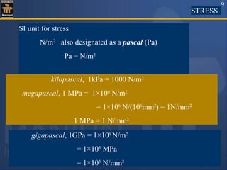
![Strength of Materials CIE 102
[3 1 0 4]
for
First Year B.E. Degree Students
1](https://image.slidesharecdn.com/1-180511185238/85/Normal-stress-and-strain-1-320.jpg)


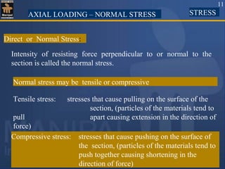


![Relationship between volumetric strain and linear strain
Relative to the unstressed state, the change in
volume per unit volume is
( )( )( )[ ] [ ]
eunit volumperin volumechange
111111
1
=
++=
−+++=−+++=
zyx
zyxzyx
dV
εεε
εεεεεε
Consider a cube of side 1unit, subjected to
three mutually perpendicular direct stresses as
shown in the figure.
92](https://image.slidesharecdn.com/1-180511185238/85/Normal-stress-and-strain-92-320.jpg)


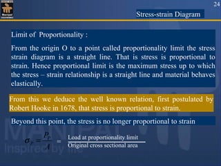
![Relationship between young’s modulus of elasticity (E) and modulus
of rigidity (G) :-
τ
τ
A1
φφ
B1
A
D
B
a
a
45˚
C
H
95
Consider a square element ABCD of side ‘a’
subjected to pure shear ‘τ’. DA'B'C is the
deformed shape due to shear τ.
Drop a perpendicular AH to diagonal A'C.
σAC μσDB
E E
-Strain in the diagonal AC =
τ μ (- τ)
E E
= -
τ [ 1 + μ ]
E
= -------(1)
(A'C–AC) (A'C–CH) A'H
AC AC AC
Strain along diagonal AC = = =](https://image.slidesharecdn.com/1-180511185238/85/Normal-stress-and-strain-95-320.jpg)
![E = 2G(1+ μ)
96
In Δle AA'H, Cos 45˚ = A'H/AA' => A'H= AA' × 1/√2
AC = √2 × AD ( AC = √ AD2
+AD2
)
Strain along the diagonal AC = =
φ
2
----(2)
A'H
AC
AA'
(√2 × √2 × AD)
=
Modulus of rigidity = G =
τ
φ
τ
G
=> φ =
Equating (1) & (3)
τ τ
2G E[1+μ]
=
Substituting in (2) Strain along the diagonal AC = -----------(3)τ](https://image.slidesharecdn.com/1-180511185238/85/Normal-stress-and-strain-96-320.jpg)
![Substituting in (1)
E = 2G[ 1+(3K – 2G)/ (2G+6K)]
E = 18GK/( 2G+6K)
E = 9GK/(G+3K)
Relationship between E, G, and K:-
We have
E = 2G( 1+ μ) -----------(1)
E = 3K( 1- 2μ) -----------(2)
Equating (1) & (2)
2G( 1+ μ) =3K( 1- 2μ)
2G + 2Gμ=3K- 6Kμ
μ= (3K- 2G) /(2G +6K)
97](https://image.slidesharecdn.com/1-180511185238/85/Normal-stress-and-strain-97-320.jpg)

![(2) A tension test is subjected on a mild steel tube of external diameter
18mm and internal diameter 12mm acted upon by an axial load of
2KN produces an extension of 3.36 x 10⁻³
mm on a length of 50mm
and a lateral contraction of 3.62 x 10⁻⁴
mm of outer diameter.
Determine E, μ,G and K.
(i) E = Stress/Strain = (2 ×103
× 50)/ (π/4(182
– 122
)× 3.36× 10⁻³
)
= 2.11× 10⁵
N/mm2
ii) μ=lateral strain/longitudinal strain
= [(3.62 ×10⁻⁴
)/18]/[(3.36 × 10-3
)/50] = 0.3
iii) E = 2G (1 + μ)
G = E / 2(1+ μ) = (2.11 × 10⁵
)/(2 × 1.3) = 81.15 × 10³
N/mm2
iv) E = 3K(1 -2 μ) => K = E/ [3×(1-2 μ)]
5 3 2
99](https://image.slidesharecdn.com/1-180511185238/85/Normal-stress-and-strain-99-320.jpg)


This document provides information about the Strength of Materials CIE 102 course for first year B.E. degree students. It includes a list of 10 topics that will be covered in the course, such as simple stress and strain, shearing force and bending moment, and stability of columns. It also lists several reference books for the course and provides an overview of concepts that will be discussed in the first chapter, including stress, strain, stress-strain diagrams, and ductile vs brittle materials.


