SlideShare a Scribd company logo
1 of 131
Download to read offline
SECTION 1– DESIGN FOR SIMPLE STRESSES
2
TENSION, COMPRESSION, SHEAR
DESIGN PROBLEMS
1. The link shown, made of AISI C1045 steel, as rolled, is subjected to a tensile load
of 8000 lb. Let bh 5.1= . If the load is repeated but not reversed, determine the
dimensions of the section with the design based on (a) ultimate strength, (b) yield
strength. (c) If this link, which is 15 in. long., must not elongate more than 0.005
in., what should be the dimensions of the cross section?
Problems 1 – 3.
Solution:
For AISI C1045 steel, as rolled (Table AT 7)
ksisu 96=
ksisy 59=
psiE 6
1030×=
A
F
sd =
where
lbF 8000=
bhA =
but
bh 5.1=
therefore 2
5.1 bA =
(a) Based on ultimate strength
N = factor of safety = 6 for repeated but not reversed load (Table 1.1)
A
F
N
s
s u
d ==
2
5.1
8000
6
000,96
b
=
inb 577.0= say in
8
5
.
SECTION 1– DESIGN FOR SIMPLE STRESSES
3
inbh
16
15
5.1 ==
(b) Based on yield strength
N = factor of safety = 3 for repeated but not reversed load (Table 1.1)
A
F
N
s
s u
d ==
2
5.1
8000
3
000,59
b
=
inb 521.0= say in
16
9
.
inbh
32
27
5.1 ==
(c) Elongation =
AE
FL
=δ
where,
in005.0=δ
lbF 8000=
psiE 6
1030×=
inL 15=
2
5.1 bA =
then,
AE
FL
=δ
( )( )
( )( )62
10305.1
158000
005.0
×
=
b
inb 730.0= say in
4
3
.
inbh
8
1
15.1 ==
2. The same as 1 except that the material is malleable iron, ASTM A47-52, grade 35
018.
Solution:
For malleable iron, ASTM A47-52, grade 35 018(Table AT 6)
ksisu 55=
ksisy 5.36=
psiE 6
1025×=
SECTION 1– DESIGN FOR SIMPLE STRESSES
4
A
F
sd =
where
lbF 8000=
bhA =
but
bh 5.1=
therefore 2
5.1 bA =
(a) Based on ultimate strength
N = factor of safety = 6 for repeated but not reversed load (Table 1.1)
A
F
N
s
s u
d ==
2
5.1
8000
6
000,55
b
=
inb 763.0= say in
8
7
.
inbh
16
5
15.1 ==
(b) Based on yield strength
N = factor of safety = 3 for repeated but not reversed load (Table 1.1)
A
F
N
s
s u
d ==
2
5.1
8000
3
500,36
b
=
inb 622.0= say in
16
11
.
inbh
32
1
15.1 ==
(c) Elongation =
AE
FL
=δ
where,
in005.0=δ
lbF 8000=
psiE 6
1025×=
inL 15=
2
5.1 bA =
then,
SECTION 1– DESIGN FOR SIMPLE STRESSES
5
AE
FL
=δ
( )( )
( )( )62
10255.1
158000
005.0
×
=
b
inb 8.0= say in
8
7
.
inbh
16
5
15.1 ==
3. The same as 1 except that the material is gray iron, ASTM 30.
Solution:
For ASTM 30 (Table AT 6)
ksisu 30= , no ys
psiE 6
105.14 ×=
Note: since there is no ys for brittle materials. Solve only for (a) and (c)
A
F
sd =
where
lbF 8000=
bhA =
but
bh 5.1=
therefore 2
5.1 bA =
(a) Based on ultimate strength
N = factor of safety = 7 ~ 8 say 7.5 (Table 1.1)
A
F
N
s
s u
d ==
2
5.1
8000
5.7
000,30
b
=
inb 1547.1= say in
16
3
1 .
inbh
32
25
15.1 ==
(c) Elongation =
AE
FL
=δ
where,
in005.0=δ
lbF 8000=
psiE 6
105.14 ×=
SECTION 1– DESIGN FOR SIMPLE STRESSES
6
inL 15=
2
5.1 bA =
then,
AE
FL
=δ
( )( )
( )( )62
105.145.1
158000
005.0
×
=
b
inb 050.1= say in
16
1
1 .
inbh
32
19
15.1 ==
4. A piston rod, made of AISI 3140 steel, OQT 1000 F (Fig. AF 2), is subjected to a
repeated, reversed load. The rod is for a 20-in. air compressor, where the
maximum pressure is 125 psig. Compute the diameter of the rod using a design
factor based on (a) ultimate strength, (b) yield strength.
Solution:
From Fig. AF 2 for AISI 3140, OQT 1000 F
ksisu 5.152=
ksisy 5.132=
( ) ( ) kipslbforceF 27.39270,3912520
4
2
====
π
From Table 1.1, page 20
8=uN
4=yN
(a) Based on ultimate strength
u
u
s
FN
A =
( )( )
5.152
27.398
4
2
=d
π
ind 62.1= say in
8
5
1
(b) Based on yield strength
y
y
s
FN
A =
( )( )
5.132
27.394
4
2
=d
π
SECTION 1– DESIGN FOR SIMPLE STRESSES
7
ind 23.1= say in
4
1
1
5. A hollow, short compression member, of normalized cast steel (ASTM A27-58,
65 ksi), is to support a load of 1500 kips with a factor of safety of 8 based on the
ultimate strength. Determine the outside and inside diameters if io DD 2= .
Solution:
ksisu 65=
8=uN
kipsF 1500=
( ) ( ) 4
3
4
44
2
2222 i
iiio
D
DDDDA
πππ
=−=−=
( )( )
65
15008
4
3 2
===
u
ui
s
FND
A
π
inDi 85.8= say in
8
7
8
inDD io
4
3
17
8
7
822 =





==
6. A short compression member with io DD 2= is to support a dead load of 25 tons.
The material is to be 4130 steel, WQT 1100 F. Calculate the outside and inside
diameters on the basis of (a) yield strength, (b) ultimate strength.
Solution:
From Table AT 7 for 4130, WQT 1100 F
ksisu 127=
ksisy 114=
From Table 1.1 page 20, for dead load
4~3=uN , say 4
2~5.1=yN , say 2
Area, ( ) ( ) 4
3
4
44
2
2222 i
iiio
D
DDDDA
πππ
=−=−=
kipstonsF 5025 ==
(a) Based on yield strength
( )( )
114
502
4
3 2
===
y
yi
s
FND
A
π
SECTION 1– DESIGN FOR SIMPLE STRESSES
8
inDi 61.0= say in
8
5
inDD io
4
1
1
8
5
22 =





==
(b) Based on ultimate strength
( )( )
127
504
4
3 2
===
u
ui
s
FND
A
π
inDi 82.0= say in
8
7
inDD io
4
3
1
8
7
22 =





==
7. A round, steel tension member, 55 in. long, is subjected to a maximum load of
7000 lb. (a) What should be its diameter if the total elongation is not to exceed
0.030 in? (b) Choose a steel that would be suitable on the basis of yield strength if
the load is gradually applied and repeated (not reversed).
Solution:
(a)
AE
FL
=δ or
E
FL
A
δ
=
where,
lbF 7000=
inL 55=
in030.0=δ
psiE 6
1030×=
( )( )
( )( )6
2
1030030.0
557000
4 ×
== dA
π
ind 74.0= say in
4
3
(b) For gradually applied and repeated (not reversed) load
3=yN
( )( )
( )
psi
A
FN
s
y
y 534,47
75.0
4
70003
2
===
π
ksisy 48≈
say C1015 normalized condition ( ksisy 48= )
8. A centrifuge has a small bucket, weighing 0.332 lb. with contents, suspended on a
manganese bronze pin (B138-A, ½ hard) at the end of a horizontal arm. If the pin
is in double shear under the action of the centrifugal force, determine the diameter
SECTION 1– DESIGN FOR SIMPLE STRESSES
9
needed for 10,000 rpm of the arm. The center of gravity of the bucket is 12 in.
from the axis of rotation.
Solution:
From Table AT 3, for B138-A, ½ hard
ksisus 48=
r
g
W
F 2
ω=
where
lbW 332.0=
2
2.32 fpsg =
( ) sec1047
60
000,102
60
2
rad
n
===
ππ
ω
inr 12=
( ) ( ) kipslbr
g
W
F 3.11300,1111047
2.32
332.0 22
==== ω
From Table 1.1, page 20
4~3=N , say 4
u
u
s
FN
A =
( )( )
48
3.114
4
2 2
=





d
π
for double shear
ind 774.0= say in
32
25
CHECK PROBLEMS
9. The link shown is made of AISIC1020 annealed steel, with inb
4
3
= and
inh
2
1
1= . (a) What force will cause breakage? (b) For a design factor of 4 based
on the ultimate strength, what is the maximum allowable load? (c) If 5.2=N
based on the yield strength, what is the allowable load?
Problem 9.
SECTION 1– DESIGN FOR SIMPLE STRESSES
10
Solution:
For AISI C1020 annealed steel, from Table AT 7
ksisu 57=
ksisy 42=
(a) AsF u=
2
125.1
2
1
1
4
3
inbhA =











==
( )( ) kipsF 64125.157 ==
(b)
u
u
N
As
F =
4=uN
2
125.1
2
1
1
4
3
inbhA =











==
( )( ) kipsF 16
4
125.157
==
(c)
y
y
N
As
F =
5.2=yN
2
125.1
2
1
1
4
3
inbhA =











==
( )( ) kipsF 9.18
2
125.142
==
10. A ¾-in.bolt, made of cold-finished B1113, has an effective stress area of 0.334 sq.
in. and an effective grip length of 5 in. The bolt is to be loaded by tightening until
the tensile stress is 80 % of the yield strength, as determined by measuring the
total elongation. What should be the total elongation?
Solution:
E
sL
=δ
from Table AT 7 for cold-finished B1113
ksisy 72=
then, ( ) ksiss y 6.57728.080.0 ===
ksipsiE 000,301030 6
=×=
( )( ) in
E
sL
0096.0
000,30
56.57
===δ
SECTION 1– DESIGN FOR SIMPLE STRESSES
11
11. A 4-lb. weight is attached by a 3/8-in. bolt to a rotating arm 14-in. from the center
of rotation. The axis of the bolts is normal to the plane in which the centrifugal
force acts and the bolt is in double shear. At what speed will the bolt shear in two
if it is made of AISI B1113, cold finish?
Solution:
From Table AT 7, psiksisus 000,6262 ==
( ) 2
2
2209.0
8
3
4
1
2 inA =











= π
Asr
g
W
F us== 2
ω
( ) ( )( )2209.0000,6214
2.32
4 2
=ω
sec74.88 rad=ω
74.88
60
2
==
nπ
ω
rpmn 847=
12. How many ¾-in. holes could be punched in one stroke in annealed steel plate of
AISI C1040, 3/16-in. thick, by a force of 60 tons?
Solution:
For AISI C1040, from Figure AF 1
ksisu 80=
( ) ksiksiss uus 608075.075.0 ===
2
4418.0
16
3
4
3
intdA =











== ππ
kipstonsF 12060 ==
n = number of holes
( )( )
5
604415.0
120
===
usAs
F
n holes
13. What is the length of a bearing for a 4-in. shaft if the load on the bearing is 6400
lb. and the allowable bearing pressure is 200 psi of the projected area?
Solution:
WpDL =
where
psip 200=
inD 4=
SECTION 1– DESIGN FOR SIMPLE STRESSES
12
lbW 6400=
( )( ) 64004200 =L
inL 8=
BENDING STRESSES
DESIGN PROBLEMS
14. A lever keyed to a shaft is inL 15= long and has a rectangular cross section of
th 3= . A 2000-lb load is gradually applied and reversed at the end as shown; the
material is AISI C1020, as rolled. Design for both ultimate and yield strengths. (a)
What should be the dimensions of a section at ina 13= ? (b) at inb 4= ? (c) What
should be the size where the load is applied?
Problem 14.
Solution:
For AISI C1020, as rolled, Table AT 7
ksisu 65=
ksisy 49=
Design factors for gradually applied and reversed load
8=uN
4=yN
12
3
th
I = , moment of inertial
but th 3=
36
4
h
I =
Moment Diagram (Load Upward)
SECTION 1– DESIGN FOR SIMPLE STRESSES
13
Based on ultimate strength
u
u
N
s
s =
(a)
I
Fac
I
Mc
s ==
2
h
c =
kipslbsF 22000 ==
( )( )












==
36
2
132
8
65
4
h
h
s
inh 86.3=
in
h
t 29.1
3
86.3
3
===
say
ininh
2
1
45.4 ==
inint
2
1
15.1 ==
(b)
I
Fbc
I
Mc
s ==
2
h
c =
kipslbsF 22000 ==
( )( )












==
36
2
42
8
65
4
h
h
s
inh 61.2=
in
h
t 87.0
3
61.2
3
===
say
inh 3=
int 1=
(c)
SECTION 1– DESIGN FOR SIMPLE STRESSES
14
413
35.4
4
3
−
−
=
− h
inh 33.2=
413
15.1
4
1
−
−
=
− t
int 78.0=
say
inh 625.2= or inh
8
5
2=
15. A simple beam 54 in. long with a load of 4 kips at the center is made of cast steel,
SAE 080. The cross section is rectangular (let bh 3≈ ). (a) Determine the
dimensions for 3=N based on the yield strength. (b) Compute the maximum
deflection for these dimensions. (c) What size may be used if the maximum
deflection is not to exceed 0.03 in.?
Solution:
For cast steel, SAE 080 (Table AT 6)
ksisy 40=
psiE 6
1030×=
SECTION 1– DESIGN FOR SIMPLE STRESSES
15
From Table AT 2
Max.
( )( ) inkips
FL
M −=== 54
4
544
4
12
3
bh
I =
but bh 3=
36
4
h
I =
(a)
I
Mc
N
s
s
y
y
==
2
h
c =
( )












=
36
2
54
3
40
4
h
h
inh 18.4=
in
h
b 39.1
3
18.4
3
===
say inh
2
1
4= , inin
h
b
2
1
15.1
3
5.4
3
====
(b)
( )( )
( ) ( )( )
in
EI
FL
0384.0
12
5.45.1
103048
544000
48 3
6
33
=






×
==δ
(c)






=
36
48
4
3
h
E
FL
δ
( )( ) ( )
( )( )46
3
103048
36544000
03.0
h×
=
inh 79.4=
in
h
b 60.1
3
79.4
3
===
say ininh
4
1
525.5 == , inin
h
b
4
3
175.1
3
25.5
3
====
SECTION 1– DESIGN FOR SIMPLE STRESSES
16
16. The same as 15, except that the beam is to have a circular cross section.
Solution:
(a)
I
Mc
N
s
s
y
y
==
64
4
d
I
π
=
2
d
c =
34
32
64
2
d
M
d
d
M
s
ππ
=












=
( )
3
5432
3
40
dπ
=
ind 46.3=
say ind
2
1
3=
(b)
EI
FL
48
3
=δ
64
4
d
I
π
=
( )
( )( )
( )( )( )
in
dE
FL
0594.0
5.3103048
54400064
48
64
46
3
4
3
=
×
==
ππ
δ
(c)
( )4
3
48
64
dE
FL
π
δ =
( )( )
( )( ) 46
3
103048
54400064
03.0
dπ×
=
ind 15.4=
say ind
4
1
4=
17. A simple beam, 48 in. long, with a static load of 6000 lb. at the center, is made of
C1020 structural steel. (a) Basing your calculations on the ultimate strength,
determine the dimensions of the rectangular cross section for bh 2= . (b)
Determine the dimensions based on yield strength. (c) Determine the dimensions
using the principle of “limit design.”
SECTION 1– DESIGN FOR SIMPLE STRESSES
17
Solution:
From Table AT 7 and Table 1.1
ksisu 65=
ksisy 48=
4~3=uN , say 4
2~5.1=yN , say 2
( )( ) kipsin
FL
M −=== 72
4
486
4
I
Mc
s =
2
h
c =
12
3
bh
I =
but
2
h
b =
24
4
h
I =
34
12
24
2
h
M
h
h
M
s =






=
(a) Based on ultimate strength
3
12
h
M
N
s
s
u
u
==
( )
3
7212
4
65
h
=
inh 76.3=
SECTION 1– DESIGN FOR SIMPLE STRESSES
18
in
h
b 88.1
2
76.3
2
===
say ininh
4
3
375.3 == , inin
h
b
8
7
1875.1
2
75.3
2
====
(b) Based on yield strength
3
12
h
M
N
s
s
y
y
==
( )
3
7212
2
48
h
=
inh 30.3=
in
h
b 65.1
2
30.3
2
===
say ininh
2
1
35.3 == , inin
h
b
4
3
175.1
2
5.3
2
====
(c) Limit design (Eq. 1.6)
4
2
bh
sM y=
( )
4
2
4872
2
h
h






=
inh 29.2=
in
h
b 145.1
2
29.2
2
===
say ininh
2
1
25.2 == , inin
h
b
4
1
125.1
2
5.2
2
====
18. The bar shown is subjected to two vertical loads, 1F and 2F , of 3000 lb. each, that
are inL 10= apart and 3 in. ( a ,d ) from the ends of the bar. The design factor is 4
based on the ultimate strength; bh 3= . Determine the dimensions h and b if the
bar is made of (a) gray cast iron, SAE 111; (b) malleable cast iron, ASTM A47-
52, grade 35 018; (c) AISI C1040, as rolled (Fig. AF 1). Sketch the shear and
moment diagrams approximately to scale.
SECTION 1– DESIGN FOR SIMPLE STRESSES
19
Problems18, 19.
Solution:
lbRRFF 30002121 ====
Moment Diagram
( )( ) inkipsinlbsaRM −=−=== 99000330001
N = factor of safety = 4 based on us
12
3
bh
I =
2
h
c =
3612
3 4
3
h
h
h
I =






=
(a) For gray cast iron, SAE 111
ksisu 30= , Table AT 6
34
18
36
2
h
M
h
h
M
I
Mc
N
s
s u
=












===
( )
3
918
4
30
h
s ==
inh 78.2=
in
h
b 93.0
3
78.2
3
===
say inh 5.3= , inb 1=
(b) For malleable cast iron, ASTM A47-52, grade 35 018
SECTION 1– DESIGN FOR SIMPLE STRESSES
20
ksisu 55= , Table AT 6
34
18
36
2
h
M
h
h
M
I
Mc
N
s
s u
=












===
( )
3
918
4
55
h
s ==
inh 28.2=
in
h
b 76.0
3
28.2
3
===
say inh
4
1
2= , inb
4
3
=
(c) For AISI C1040, as rolled
ksisu 90= , Fig. AF 1
34
18
36
2
h
M
h
h
M
I
Mc
N
s
s u
=












===
( )
3
918
4
90
h
s ==
inh 93.1=
in
h
b 64.0
3
93.1
3
===
say inh
8
7
1= , inb
8
5
=
19. The same as 18, except that 1F acts up ( 2F acts down).
Solution:
[ ]∑ = 0AM lbRR 187521 ==
SECTION 1– DESIGN FOR SIMPLE STRESSES
21
Shear Diagram
Moment Diagram
=M maximum moment = 5625 lb-in = 5.625 kips-in
(a) For gray cast iron
3
18
h
M
N
s
s u
==
( )
3
625.518
4
30
h
=
inh 38.2=
in
h
b 79.0
3
38.2
3
===
say inh
4
1
2= , inb
4
3
=
(b) For malleable cast iron
3
18
h
M
N
s
s u
==
( )
3
625.518
4
55
h
=
inh 95.1=
in
h
b 65.0
3
95.1
3
===
say inh
8
7
1= , inb
8
5
=
SECTION 1– DESIGN FOR SIMPLE STRESSES
22
(c) For AISI C1040, as rolled
3
18
h
M
N
s
s u
==
( )
3
625.518
4
90
h
=
inh 65.1=
in
h
b 55.0
3
65.1
3
===
say inh
2
1
1= , inb
2
1
=
20. The bar shown, supported at A and B , is subjected to a static load F of 2500 lb.
at 0=θ . Let ind 3= , inL 10= and bh 3= . Determine the dimensions of the
section if the bar is made of (a) gray iron, SAE 110; (b) malleable cast iron,
ASTM A47-52, grade 32 510; (c) AISI C1035 steel, as rolled. (d) For economic
reasons, the pins at A, B, and C are to be the same size. What should be their
diameter if the material is AISI C1035, as rolled, and the mounting is such that
each is in double shear? Use the basic dimensions from (c) as needed. (e) What
sectional dimensions would be used for the C1035 steel if the principle of “limit
design” governs in (c)?
Problems 20, 21.
Solution:
SECTION 1– DESIGN FOR SIMPLE STRESSES
23
[ ]∑ = 0AM ( )2500133 =BR
lbRB 833,10=
[ ]∑ = 0BM ( )2500103 =AR
lbRA 8333=
Shear Diagram
Moment Diagram
( )( ) inkipsinlbM −=−== 25000,25102500
bh 3=
12
3
bh
I =
36
4
h
I =
2
h
c =
34
18
36
2
h
M
h
h
M
I
Mc
s =












==
(a) For gray cast iron, SAE 110
ksisu 20= , Table AT 6
6~5=N , say 6 for cast iron, dead load
3
18
h
M
N
s
s u
==
( )
3
2518
6
20
h
=
SECTION 1– DESIGN FOR SIMPLE STRESSES
24
inh 13.5=
in
h
b 71.1
3
==
say inh
4
1
5= , inb
4
3
1=
(b) For malleable cast iron, ASTM A47-32 grade 32510
ksisu 52= , ksisy 34=
4~3=N , say 4 for ductile, dead load
3
18
h
M
N
s
s u
==
( )
3
2518
4
52
h
=
inh 26.3=
in
h
b 09.1
3
==
say inh
4
3
3= , inb
4
1
1=
(c) For AISI C1035, as rolled
ksisu 85= , ksisy 55=
4=N , based on ultimate strength
3
18
h
M
N
s
s u
==
( )
3
2518
4
85
h
=
inh 77.2=
in
h
b 92.0
3
==
say inh 3= , inb 1=
(d) For AISI C1035, as rolled
ksissu 64=
4=N , kipsRB 833.10=
A
R
N
s
s Bsu
s ==
22
24
2 DDA
ππ
=





=
2
2
833.10
4
64
D
ss
π
==
inD 657.0=
SECTION 1– DESIGN FOR SIMPLE STRESSES
25
say inD
16
11
=
(e) Limit Design
4
2
bh
sM y=
For AISI C1035 steel, ksisy 55=
3
h
b =
( )
4
3
5525
2
h
h
M






==
inh 76.1=
in
h
b 59.0
3
==
say ininh
8
7
1875.1 == , inb
8
5
=
21. The same as 20, except that o
30=θ . Pin B takes all the horizontal thrust.
Solution:
θcosFFV =
[ ]∑ = 0AM VB FR 133 =
( ) 30cos2500133 =BR
lbRB 9382=
[ ]∑ = 0BM VA FR 103 =
( ) 30cos2500103 =AR
lbRA 7217=
Shear Diagram
SECTION 1– DESIGN FOR SIMPLE STRESSES
26
Moment Diagram
( )( ) inkipsinlbM −=−== 65.21650,21102165
3
18
h
M
s =
(a) For gray cast iron, SAE 110
ksisu 20= , Table AT 6
6~5=N , say 6 for cast iron, dead load
3
18
h
M
N
s
s u
==
( )
3
65.2118
6
20
h
=
inh 89.4=
in
h
b 63.1
3
==
say inh
4
1
5= , inb
4
3
1=
(b) For malleable cast iron, ASTM A47-32 grade 32510
ksisu 52= , ksisy 34=
4~3=N , say 4 for ductile, dead load
3
18
h
M
N
s
s u
==
( )
3
65.2118
4
52
h
=
inh 11.3=
in
h
b 04.1
3
==
say inh 3= , inb 1=
(c) For AISI C1035, as rolled
ksisu 85= , ksisy 55=
4=N , based on ultimate strength
SECTION 1– DESIGN FOR SIMPLE STRESSES
27
3
18
h
M
N
s
s u
==
( )
3
65.2118
4
85
h
=
inh 64.2=
in
h
b 88.0
3
==
say inh
8
5
2= , inb
8
7
=
(d) For AISI C1035, as rolled
ksissu 64=
4=N , lbRBV 9382=
lbFFR HBH 125030sin2500sin ==== θ
( ) ( )22222
12509382 +=+= BHBVB RRR
lbRB 9465=
A
R
N
s
s Bsu
s ==
22
24
2 DDA
ππ
=





=
2
2
465.9
4
64
D
ss
π
==
inD 614.0=
say inD
8
5
=
(e) Limit Design
4
2
bh
sM y=
For AISI C1035 steel, ksisy 55=
3
h
b =
( )
4
3
5565.21
2
h
h
M






==
inh 68.1=
in
h
b 56.0
3
==
say ininh
8
7
1875.1 == , inb
8
5
=
SECTION 1– DESIGN FOR SIMPLE STRESSES
28
22. A cast-iron beam, ASTM 50, as shown, is 30 in. long and supports two gradually
applied, repeated loads (in phase), one of 2000 lb. at ine 10= from the free end,
and one of 1000 lb at the free end. (a) Determine the dimensions of the cross
section if acb 3≈= . (b) The same as (a) except that the top of the tee is below.
Problem 22.
Solution:
For cast iron, ASTM 50
ksisu 50= , ksisuc 164=
For gradually applied, repeated load
8~7=N , say 8
( )edFdFM ++= 21
where:
lbF 20001 =
lbF 10002 =
ind 201030 =−=
ined 30=+
( )( ) ( )( ) inkipsinlbM −=−=+= 70000,70301000202000
I
Mc
s =
Solving for I , moment of inertia
( )( ) ( )( ) ( )( ) ( )( )[ ]yaaaa
a
aa
a
aa 33
2
5
3
2
3 +=





+





2
3a
y =
SECTION 1– DESIGN FOR SIMPLE STRESSES
29
( )( ) ( )( )( ) ( )( ) ( )( )( ) 2
17
3
12
3
3
12
3 4
2
3
2
3
a
aaa
aa
aaa
aa
I =+++=
(a)
2
3a
ct =
2
5a
cc =
Based on tension
I
Mc
N
s
s tu
t ==
( )












=
2
17
2
3
70
8
50
4
a
a
ina 255.1=
Based on compression
I
Mc
N
s
s cuc
c ==
( )












=
2
17
2
5
70
8
164
4
a
a
ina 001.1=
Therefore ina 255.1=
Or say ina
4
1
1=
And ( ) inacb 75.325.133 ====
SECTION 1– DESIGN FOR SIMPLE STRESSES
30
Or incb
4
3
3==
(b) If the top of the tee is below
2
5a
ct =
2
3a
cc =
2
17 4
a
I =
inkipsM −= 70
Based on tension
I
Mc
N
s
s tu
t ==
( )












=
2
17
2
5
70
8
50
4
a
a
ina 488.1=
Based on compression
I
Mc
N
s
s cuc
c ==
( )












=
2
17
2
3
70
8
164
4
a
a
ina 845.0=
Therefore ina 488.1=
Or say ina
2
1
1=
And inacb
2
1
43 ===
CHECK PROBLEMS
SECTION 1– DESIGN FOR SIMPLE STRESSES
31
23. An I-beam is made of structural steel, AISI C1020, as rolled. It has a depth of 3
in. and is subjected to two loads; 1F and 12 2FF = ; 1F is 5 in. from one end and
2F is 5 in. from the other ends. The beam is 25 in. long; flange width is
inb 509.2= ; 4
9.2 inIx = . Determine (a) the approximate values of the load to
cause elastic failure, (b) the safe loads for a factor of safety of 3 based on the yield
strength, (c) the safe load allowing for flange buckling (i1.24), (f) the maximum
deflection caused by the safe loads.
Problems 23 – 25.
Solution:
[ ]∑ = 0AM ( ) BRFF 252205 11 =+
18.1 FRB =
[ ]∑ = 0VF BA RRFF +=+ 11 2
111 2.18.13 FFFRA =−=
Shear Diagram
Moment Diagram
SECTION 1– DESIGN FOR SIMPLE STRESSES
32
19FM = = maximum moment
For AISI C1020, as rolled
ksisy 48=
(a)
I
Mc
sy =
where in
d
c 5.1
2
3
2
===
( )( )
9.2
5.19
48 1F
sy ==
kipsF 31.101 =
kipsFF 62.202 12 ==
(b)
I
Mc
N
s
s y
==
( )( )
9.2
5.19
3
48 1F
s ==
kipsF 44.31 =
kipsFF 88.62 12 ==
(c) 1596.9
509.2
25
<==
b
L
(page 34)
ksisc 20= ( page 34, i1.24)
I
Mc
sc =
( )( )
9.2
5.19
20 1F
=
kipsF 30.41 =
kipsFF 60.82 12 ==
(d) For maximum deflection,
by method of superposition, Table AT 2
( ) 2
3
max
33 


 ′+′
=
bLa
EIL
bF
y , ba ′>
or
( ) 2
3
max
33 


 +′
=
aLb
EIL
Fa
y , ab >′
SECTION 1– DESIGN FOR SIMPLE STRESSES
33
maxy caused by 1F
( ) 2
3
1111
max
331 


 +′
=
aLb
EIL
aF
y , 11 ab >′
where ksiE 000,30=
ina 51 =
inb 201 =′
inL 25=
4
9.2 inI =
( )
( )( )( )
( )
1
2
3
1
max 0022.0
3
52520
259.2000,303
5
1
F
F
y =


 +
=
maxy caused by 2F
( ) 2
3
2222
max
332 


 ′+′
=
bLa
EIL
bF
y , 22 ba ′>
where inb 52 =′
ina 202 =
( )
( )( )( )
( )
1
2
3
1
max 0043.0
3
52520
259.2000,303
52
2
F
F
y =


 +
=
Total deflection = δ
111maxmax 0065.00043.0022.021
FFFyy =+=+=δ
Deflection caused by the safe loads in (a)
( ) ina 067.031.100065.0 ==δ
Deflection caused by the safe loads in (b)
( ) inb 022.044.30065.0 ==δ
Deflection caused by the safe loads in (c)
( ) inc 028.030.40065.0 ==δ
24. The same as 23, except that the material is aluminum alloy, 2024-T4, heat treated.
Solution:
For aluminum alloy, 2024-T4, heat treated
ksisy 47=
(a)
I
Mc
sy =
SECTION 1– DESIGN FOR SIMPLE STRESSES
34
( )( )
9.2
5.19
47 1F
sy ==
kipsF 10.101 =
kipsFF 20.202 12 ==
(b)
I
Mc
N
s
s y
==
( )( )
9.2
5.19
3
47 1F
s ==
kipsF 36.31 =
kipsFF 72.62 12 ==
(c) 1596.9
509.2
25
<==
b
L
(page 34)
ksisc 20= ( page 34, i1.24)
I
Mc
sc =
( )( )
9.2
5.19
20 1F
=
kipsF 30.41 =
kipsFF 60.82 12 ==
(d) Total deflection = δ
111maxmax 0065.00043.0022.021
FFFyy =+=+=δ
Deflection caused by the safe loads in (a)
( ) ina 066.010.100065.0 ==δ
Deflection caused by the safe loads in (b)
( ) inb 022.036.30065.0 ==δ
Deflection caused by the safe loads in (c)
( ) inc 028.030.40065.0 ==δ
25. A light I-beam is 80 in. long, simply supported, and carries a static load at the
midpoint. The cross section has a depth of ind 4= , a flange width of inb 66.2= ,
and 4
0.6 inIx = (see figure). (a) What load will the beam support if it is made of
C1020, as-rolled steel, and flange buckling (i1.24) is considered? (b) Consider the
stress owing to the weight of the beam, which is 7.7 lb/ft, and decide whether or
not the safe load should be less.
SECTION 1– DESIGN FOR SIMPLE STRESSES
35
Solution:
(a) For C1020, as rolled, ksisu 65=
Consider flange buckling
30
66.2
80
==
b
L
since 4015 <<
b
L
( )
ksi
b
L
sc 15
1800
30
1
5.22
18001
5.22
22
=
+
=






+
=
I
Mc
s =
in
d
c 2
2
4
2
===
From Table AT 2
( ) F
FFL
M 20
4
80
4
===
I
Mc
ss c ==
( )( )
6
220
15
F
=
kipsF 25.2= , safe load
(b) Considering stress owing to the weight of the beam
add’l
8
2
wL
M = (Table AT 2)
where ftlbw 7.7=
SECTION 1– DESIGN FOR SIMPLE STRESSES
36
add’l
( ) inkipsinlb
wL
M −=−=





== 513.0513
8
80
12
7.7
8
22
513.020 += FM = total moment
I
Mc
ss c ==
( )( )
6
2513.020
15
+
=
F
kipsF 224.2=
Therefore, the safe load should be less.
26. What is the stress in a band-saw blade due to being bent around a 13 ¾-in. pulley?
The blade thickness is 0.0265 in. (Additional stresses arise from the initial tension
and forces of sawing.)
Solution:
in
t
c 01325.00265.0
2
===
inr 76325.1301325.075.13 =+=
Using Eq. (1.4) page 11 (Text)
r
Ec
s =
where psiE 6
1030×=
( )( ) psis 881,28
76325.13
01325.01030 6
=
×
=
27. A cantilever beam of rectangular cross section is tapered so that the depth varies
uniformly from 4 in. at the fixed end to 1 in. at the free end. The width is 2 in. and
the length 30 in. What safe load, acting repeated with minor shock, may be
applied to the free end? The material is AISI C1020, as rolled.
Solution:
For AISI C1020, as rolled
ksisu 65= (Table AT 7)
Designing based on ultimate strength,
6=N , for repeated, minor shock load
SECTION 1– DESIGN FOR SIMPLE STRESSES
37
ksi
N
s
s u
8.10
6
65
===
Loading Diagram
x
h 1
30
14 −
=
−
110.0 += xh
12
3
wh
I =
2
h
c =
FxM =
( )
( )2223
110.0
33
2
6
12
2
+
===












==
x
Fx
h
Fx
h
Fx
wh
h
Fx
I
Mc
s
Differentiating with respect to x then equate to zero to solve for x giving maximum
stress.
( ) ( ) ( )( )( )
( )
0
110.0
10.0110.021110.0
3 4
2
=





+
+−+
=
x
xxx
F
dx
ds
( ) 010.02110.0 =−+ xx
inx 10=
( ) inh 211010.0 =+=
2
3
h
Fx
N
s
s u
==
( )
( )2
2
103
8.10
F
=
kipsF 44.1=
TORSIONAL STRESSES
DESIGN PROBLEMS
SECTION 1– DESIGN FOR SIMPLE STRESSES
38
28. A centrifugal pump is to be driven by a 15-hp electric motor at 1750 rpm. What
should be the diameter of the pump shaft if it is made of AISI C1045 as rolled?
Consider the load as gradually repeated.
Solution:
For C1045 as rolled,
ksisy 59=
ksisus 72=
Designing based on ultimate strength
N
s
s us
= , 6=N (Table 1.1)
ksis 12
6
72
==
Torque,
( )
( )
kipsinlbinlbft
n
hp
T −=−=−=== 540.054045
17502
15000,33
2
000,33
ππ
For diameter,
3
16
d
T
s
π
=
( )
3
540.016
12
dπ
=
ind 612.0=
say ind
8
5
=
29. A shaft in torsion only is to transmit 2500 hp at 570 rpm with medium shocks. Its
material is AISI 1137 steel, annealed. (a) What should be the diameter of a solid
shaft? (b) If the shaft is hollow, io DD 2= , what size is required? (c) What is the
weight per foot of length of each of these shafts? Which is the lighter? By what
percentage? (d) Which shaft is the more rigid? Compute the torsional deflection
of each for a length of 10 ft.
Solution:
( )
( )
kipsinlbft
n
hp
T −=−=== 276036,23
5702
2500000,33
2
000,33
ππ
For AISI 1137, annealed
ksisy 50= (Table AT 8)
ksiss yys 306.0 ==
Designing based on yield strength
3=N for medium shock, one direction
SECTION 1– DESIGN FOR SIMPLE STRESSES
39
Design stress
ksi
N
s
s ys
10
3
30
===
(a) Let D = shaft diameter
J
Tc
s =
32
4
D
J
π
=
2
D
c =
3
16
D
T
s
π
=
( )
3
27616
10
Dπ
=
inD 20.5=
say inD
4
1
5=
(b)
( ) ( )[ ]
32
15
32
2
32
44444
iiiio DDDDD
J
πππ
=
−
=
−
=
i
io
D
DD
c ===
2
2
2
34
15
32
32
15 ii
i
D
T
D
TD
s
ππ
=






=
( )
3
15
27632
10
iDπ
=
inDi 66.2=
inDD io 32.52 ==
say
inDi
8
5
2=
inDo
4
1
5=
(c) Density, 3
284.0 inlb=ρ (Table AT 7)
SECTION 1– DESIGN FOR SIMPLE STRESSES
40
For solid shaft
=w weight per foot of length
( )( ) ftlbDDw 8.7325.5284.033
4
12
222
===





= ππρ
π
ρ
For hollow shaft
( ) ( ) ( )( ) ( )[ ] ftlbDDDDw ioio 3.55625.225.5284.033
4
12
222222
=−=−=−





= ππρ
π
ρ
Therefore hollow shaft is lighter
Percentage lightness = ( ) %5.33%100
3.55
3.558.73
=
−
(d) Torsional Deflection
JG
TL
=θ
where
inftL 12010 ==
ksiG 3
105.11 ×=
For solid shaft,
32
4
D
J
π
=
( )( )
( ) ( )
( ) o
2.2
180
039.0039.0
105.1125.5
32
120276
34
=





==
×





=
ππ
θ rad
For hollow shaft,
( )
32
44
io DD
J
−
=
π
( )( )
( ) ( )[ ]( )
( ) o
4.2
180
041.0041.0
105.11625.225.5
32
120276
344
=





==
×−





=
ππ
θ rad
Therefore, solid shaft is more rigid, oo
4.22.2 <
30. The same as 29, except that the material is AISI 4340, OQT 1200 F.
Solution:
( )
( )
kipsinlbft
n
hp
T −=−=== 276036,23
5702
2500000,33
2
000,33
ππ
For AISI 4340, OQT 1200 F
ksisy 130=
( ) ksiss yys 781306.06.0 ===
Designing based on yield strength
SECTION 1– DESIGN FOR SIMPLE STRESSES
41
3=N for mild shock
Design stress
ksi
N
s
s ys
26
3
78
===
(a) Let D = shaft diameter
J
Tc
s =
32
4
D
J
π
=
2
D
c =
3
16
D
T
s
π
=
( )
3
27616
26
Dπ
=
inD 78.3=
say inD
4
3
3=
(b)
( ) ( )[ ]
32
15
32
2
32
44444
iiiio DDDDD
J
πππ
=
−
=
−
=
i
io
D
DD
c ===
2
2
2
34
15
32
32
15 ii
i
D
T
D
TD
s
ππ
=






=
( )
3
15
27632
26
iDπ
=
inDi 93.1=
inDD io 86.32 ==
say
inDi 2=
inDo 4=
(c) Density, 3
284.0 inlb=ρ (Table AT 7)
SECTION 1– DESIGN FOR SIMPLE STRESSES
42
For solid shaft
=w weight per foot of length
( )( ) ftlbDDw 6.3775.3284.033
4
12
222
===





= ππρ
π
ρ
For hollow shaft
( ) ( ) ( )( ) ( )[ ] ftlbDDDDw ioio 1.3224284.033
4
12
222222
=−=−=−





= ππρ
π
ρ
Therefore hollow shaft is lighter
Percentage lightness = ( ) %1.17%100
1.32
1.326.37
=
−
(d) Torsional Deflection
JG
TL
=θ
where
inftL 12010 ==
ksiG 3
105.11 ×=
For solid shaft,
32
4
D
J
π
=
( )( )
( ) ( )
( ) o
48.8
180
148.0148.0
105.1175.3
32
120276
34
=





==
×





=
ππ
θ rad
For hollow shaft,
( )
32
44
io DD
J
−
=
π
( )( )
( ) ( )[ ]( )
( ) o
99.6
180
122.0122.0
105.1124
32
120276
344
=





==
×−





=
ππ
θ rad
Therefore, hollow shaft is more rigid, oo
48.899.6 < .
31. A steel shaft is transmitting 40 hp at 500 rpm with minor shock. (a) What should
be its diameter if the deflection is not to exceed 1o
in D20 ? (b) If deflection is
primary what kind of steel would be satisfactory?
Solution:
(a)
( )
( )
kipsinlbft
n
hp
T −=−=== 04.5420
5002
40000,33
2
000,33
ππ
ksiG 3
105.11 ×=
DL 20=
SECTION 1– DESIGN FOR SIMPLE STRESSES
43
rad
180
1
π
θ == o
JG
TL
=θ
( )( )
( )3
4
105.11
32
2004.5
180
×





=
D
D
π
π
inD 72.1=
say inD
4
3
1=
(b)
( )
( )
ksi
D
T
s 8.4
75.1
04.51616
33
===
ππ
Based on yield strength
3=N
( )( ) ksiNssys 4.148.43 ===
ksi
s
s ys
y 24
6.0
4.14
6.0
===
Use C1117 normalized steel ksisy 35=
32. A square shaft of cold-finish AISI 1118 transmits a torsional moment of 1200 in-
lb. For medium shock, what should be its size?
Solution:
For AISI 1118 cold-finish
ksisy 75=
ksiss yys 456.0 ==
3=N for medium shock
Z
T
N
s
s ys
′
==
where, bh =
9
2
9
2 32
bhb
Z ==′ (Table AT 1)
kipsinlbinT −=−= 2.11200
( )
3
2
92.1
3
45
b
s ==
inhb 71.0==
say inhb
4
3
==
SECTION 1– DESIGN FOR SIMPLE STRESSES
44
CHECK PROBLEMS
33. A punch press is designed to exert a force sufficient to shear a 15/16-in. hole in a
½-in. steel plate, AISI C1020, as rolled. This force is exerted on the shaft at a
radius of ¾-in. (a) Compute the torsional stress in the 3.5-in. shaft (bending
neglected). (b) What will be the corresponding design factor if the shaft is made
of cold-rolled AISI 1035 steel (Table AT 10)? Considering the shock loading that
is characteristics of this machine, do you thick the design is safe enough?
Solution:
For AISI C1020, as rolled
ksisus 49=
( )DtsF us π=
where inD
16
15
=
int
2
1
=
( ) kipsF 2.72
2
1
16
15
49 =











= π
FrT =
where inr
4
3
=
( ) kipsinT −=





= 2.54
4
3
2.72
(a) 3
16
d
T
s
π
=
where ind 5.3=
( )
( )
ksis 44.6
5.3
2.5416
3
==
π
(b) For AISI 1035 steel, ksisus 64=
for shock loading, traditional factor of safety, 15~10=N
Design factor , 94.9
44.6
64
===
s
s
N us
, the design is safe ( 10≈N )
34. The same as 33, except that the shaft diameter is 2 ¾ in.
Solution:
SECTION 1– DESIGN FOR SIMPLE STRESSES
45
ind 75.2=
(a) 3
16
d
T
s
π
=
( )
( )
ksis 3.13
75.2
2.5416
3
==
π
(b) For AISI 1035 steel, ksisus 64=
for shock loading, traditional factor of safety, 15~10=N
Design factor , 8.4
3.13
64
===
s
s
N us
, the design is not safe ( 10<N )
35. A hollow annealed Monel propeller shaft has an external diameter of 13 ½ in. and
an internal diameter of 6 ½ in.; it transmits 10,000 hp at 200 rpm. (a) Compute the
torsional stress in the shaft (stress from bending and propeller thrust are not
considered). (b) Compute the factor of safety. Does it look risky?
Solution:
For Monel shaft,
ksisus 98= (Table AT 3)
4~3=N , for dead load, based on ultimate strength
(a)
J
Tc
s =
( ) ( ) ( )[ ] 4
4444
3086
32
5.65.13
32
in
DD
J io
=
−
=
−
=
ππ
in
D
c o
75.6
2
5.13
2
===
( )
( )
kipsinlbft
n
hp
T −=−=== 3152606,262
2002
000,10000,33
2
000,33
ππ
( )( ) ksis 9.6
3086
75.63152
==
(b) Factor of safety,
2.14
9.6
98
===
s
s
N us
, not risky
SECTION 1– DESIGN FOR SIMPLE STRESSES
46
STRESS ANALYSIS
DESIGN PROBLEMS
36. A hook is attached to a plate as shown and supports a static load of 12,000 lb. The
material is to be AISI C1020, as rolled. (a) Set up strength equations for
dimensions d , D , h , and t . Assume that the bending in the plate is negligible.
(b) Determine the minimum permissible value of these dimensions. In estimating
the strength of the nut, let dD 2.11 = . (c) Choose standard fractional dimensions
which you think would be satisfactory.
Problems 36 – 38.
Solution:
s = axial stress
ss = shear stress
(a)
2
2
4
4
1 d
F
d
F
s
ππ
==
Equation (1)
s
F
d
π
4
=
SECTION 1– DESIGN FOR SIMPLE STRESSES
47
( ) ( ) ( )[ ] ( )22222
1
2
2
1
2 44.1
4
2.1
44
4
1 dD
F
dD
F
DD
F
DD
F
s
−
=
−
=
−
=
−
=
ππππ
Equation (2) 2
44.1
4
d
s
F
D +=
π
dh
F
hD
F
ss
ππ 2.11
==
Equation (3)
sds
F
h
π2.1
=
Dt
F
ss
π
=
Equation (4)
sDs
F
t
π
=
(b) Designing based on ultimate strength,
Table AT 7, AISI C1020, as rolled
ksisu 65=
ksisus 49=
4~3=N say 4, design factor for static load
ksi
N
s
s u
16
4
65
===
ksi
N
s
s us
s 12
4
49
===
kipslbF 12000,12 ==
From Equation (1)
( )
( )
in
s
F
d 98.0
16
1244
===
ππ
From Equation (2)
( )
( )
( ) ind
s
F
D 53.198.044.1
16
124
44.1
4 22
=+=+=
ππ
From Equation (3)
( )( )
in
ds
F
h
s
27.0
1298.02.1
12
2.1
===
ππ
From Equation (4)
( )( )
in
Ds
F
t
s
21.0
1253.1
12
===
ππ
SECTION 1– DESIGN FOR SIMPLE STRESSES
48
(c) Standard fractional dimensions
ind 1=
inD
2
1
1=
inh
4
1
=
int
4
1
=
37. The same as 36, except that a shock load of 4000 lb. is repeatedly applied.
Solution:
(a) Same as 36.
(b) 15~10=N for shock load, based on ultimate strength
say 15=N , others the same.
ksi
N
s
s u
4
15
65
===
ksi
N
s
s us
s 3
15
49
===
kipslbF 44000 ==
From Equation (1)
( )
( )
in
s
F
d 13.1
4
444
===
ππ
From Equation (2)
( )
( )
( ) ind
s
F
D 76.113.144.1
4
44
44.1
4 22
=+=+=
ππ
From Equation (3)
( )( )
in
ds
F
h
s
31.0
313.12.1
4
2.1
===
ππ
From Equation (4)
( )( )
in
Ds
F
t
s
24.0
376.1
4
===
ππ
SECTION 1– DESIGN FOR SIMPLE STRESSES
49
(c) Standard fractional dimensions
ind
8
1
1=
inD
4
3
1=
inh
8
3
=
int
4
1
=
38. The connection between the plate and hook, as shown, is to support a load F .
Determine the value of dimensions D , h , and t in terms of d if the connection
is to be as strong as the rod of diameter d . Assume that dD 2.11 = , uus ss 75.0= ,
and that bending in the plate is negligible.
Solution:
2
4
1
d
F
s
π
=
sdF 2
4
1
π=
(1) 





=
N
s
dF u2
4
1
π
SECTION 1– DESIGN FOR SIMPLE STRESSES
50
( ) ( )222
1
2
44.1
4
1
4
1
dD
F
DD
F
s
−
=
−
=
ππ
( )sdDF 22
44.1
4
1
−= π
(2) ( ) 





−=
N
s
dDF u22
44.1
4
1
π
dh
F
hD
F
ss
ππ 2.11
==
sdhsF π2.1=






=





=
N
s
dh
N
s
dhF uus 75.0
2.12.1 ππ
(3) 





=
N
s
dhF u5
9.0 π
Dt
F
ss
π
=
sDtsF π=






=





=
N
s
Dt
N
s
DtF uus 75.0
ππ
(4) 





=
N
s
DtF u
π75.0
Equate (2) and (1)
( ) 





=





−=
N
s
d
N
s
dDF uu 222
4
1
44.1
4
1
ππ
22
44.2 dD =
dD 562.1=
Equate (3) and (1)






=





=
N
s
d
N
s
dhF uu 2
4
1
9.0 ππ
( )
d
d
h 278.0
9.04
==
Equate (4) and (1)






=





=
N
s
d
N
s
DtF uu 2
4
1
75.0 ππ
( )( ) 





=





=
N
s
d
N
s
tdF uu 2
4
1
562.175.0 ππ
( )( )
d
d
t 214.0
562.175.04
==
SECTION 1– DESIGN FOR SIMPLE STRESSES
51
39. (a) For the connection shown, set up strength equations representing the various
methods by which it might fail. Neglect bending effects. (b) Design this
connection for a load of 2500 lb. Both plates and rivets are of AISI C1020, as
rolled. The load is repeated and reversed with mild shock. Make the connection
equally strong on the basis of yield strengths in tension, shear, and compression.
Problems 39, 40
Solution:
(a)






=
2
4
1
5 D
F
ss
π
Equation (1)
ss
F
D
π5
4
=
( )Dbt
F
s
2−
=
Equation (2) D
ts
F
b 2+=
Dt
F
s
5
=
Equation (3)
Ds
F
t
5
=
(b) For AISI C1020, as rolled
ksisy 48= (Table AT 7)
ksiss yys 286.0 ==
4=N for repeated and reversed load (mild shock) based on yield strength
ksis 12
4
48
==
ksiss 7
4
28
==
From Equation (1)
SECTION 1– DESIGN FOR SIMPLE STRESSES
52
ss
F
D
π5
4
=
where
kipslbF 5.22500 ==
( )
( )
in
s
F
D
s
30.0
75
5.24
5
4
===
ππ
say in
16
5
From Equation (3)
( )
in
Ds
F
t 13.0
12
16
5
5
5.2
5
=






== say in
32
5
From Equation (2)
( )
inD
ts
F
b 96.1
16
5
2
12
32
5
5.2
2 =





+






=+= say in2
40. The same as 39, except that the material is 2024-T4, aluminum alloy.
Solution:
(a) Same as 39.
(b) ) For 2024-T4, aluminum alloy
ksisy 47= (Table AT 3)
ksiss yys 2555.0 ==
4=N for repeated and reversed load (mild shock) based on yield strength
ksis 12
4
47
==
ksiss 6
4
25
==
From Equation (1)
ss
F
D
π5
4
=
where
kipslbF 5.22500 ==
( )
( )
in
s
F
D
s
33.0
65
5.24
5
4
===
ππ
say in
8
3
From Equation (3)
SECTION 1– DESIGN FOR SIMPLE STRESSES
53
( )
in
Ds
F
t 11.0
12
8
3
5
5.2
5
=






== say in
8
1
From Equation (2)
( )
inD
ts
F
b 42.2
8
3
2
12
8
1
5.2
2 =





+






=+= say in
2
1
2
41. (a) For the connection shown, set up strength equations representing the various
methods by which it might fail. (b) Design this connection for a load of 8000 lb.
Use AISI C1015, as rolled, for the rivets, and AISI C1020, as rolled, for the
plates. Let the load be repeatedly applied with minor shock in one direction and
make the connection equally strong on the basis of ultimate strengths in tension,
shear, and compression.
Problem 41.
Solution:
(a)
( )Dbt
F
sP
−
= or
( )Dbt
F
sP
2
4
3
−
= Equation (1)
( )2
4
1
4 2






=
D
F
ssR
π
Equation (2)
SECTION 1– DESIGN FOR SIMPLE STRESSES
54
Dt
F
sR
4
= Equation (3)
(b) For AISI C1015, as rolled
ksisuR 61= , ksiss uRusR 4575.0 ==
For AISI C1020, as rolled
ksisuP 65=
6=N , based on ultimate strength
ksi
N
s
s uP
P 8.10
6
65
===
ksi
N
s
s uR
R 1.10
6
61
===
ksi
N
s
s usR
sR 5.7
6
45
===
kipslbF 88000 ==
Solving for D
2
2 D
F
ssR
π
=
( )
in
s
F
D
sR
412.0
5.72
8
2
===
ππ
say in
16
7
Solving for t
Dt
F
sR
4
=
( )
in
Ds
F
t
R
453.0
1.10
16
7
4
8
4
=






== say in
2
1
Solving for b
Using
( )Dbt
F
sP
−
=
( )
inD
ts
F
b
P
92.1
16
7
8.10
2
1
8
=+






=+= say in2
Using
( )Dbt
F
sP
2
4
3
−
=
SECTION 1– DESIGN FOR SIMPLE STRESSES
55
( )
( )
inD
ts
F
b
P
99.1
16
7
2
8.10
2
1
4
83
2
4
3
=





+






=+= say in2
Therefore
inb 2=
inD
16
7
=
int
2
1
=
42. Give the strength equations for the connection shown, including that for the shear
of the plate by the cotter.
Problems 42 – 44.
Solution:
Axial Stresses
2
12
1
4
4
1 D
F
D
F
s
ππ
== Equation (1)
( )eDL
F
s
2−
= Equation (2)
SECTION 1– DESIGN FOR SIMPLE STRESSES
56
eD
F
s
2
= Equation (3)
( ) ( )2
2
2
2
2
2
4
4
1 Da
F
Da
F
s
−
=
−
=
ππ
Equation (4)
eDD
F
eDD
F
s
2
2
2
2
2
2
4
4
4
1 −
=
−
=
ππ
Equation (5)
Shear Stresses
eb
F
ss
2
= Equation (6)
( )teDL
F
ss
+−
=
22
Equation (7)
SECTION 1– DESIGN FOR SIMPLE STRESSES
57
at
F
ss
π
= Equation (8)
mD
F
ss
1π
= Equation (9)
hD
F
ss
22
= Equation (10)
43. A steel rod, as-rolled AISI C1035, is fastened to a 7/8-in., as-rolled C1020 plate
by means of a cotter that is made of as-rolled C1020, in the manner shown. (a)
Determine all dimensions of this joint if it is to withstand a reversed shock load
kipsF 10= , basing the design on yield strengths. (b) If all fits are free-running
fits, decide upon tolerances and allowances.
Solution: (See figure of Prob. 42)
inint 875.0
8
7
== , ysy ss 6.0=
For steel rod, AISI C1035, as rolled
ksisy 551
=
ksissy 331
=
For plate and cotter, AISI C1020, as rolled
ksisy 482
=
ksissy 282
=
7~5=N based on yield strength
say 7=N
From Equation (1) (Prob. 42)
2
1
41
D
F
N
s
s
y
π
==
( )
2
1
104
7
55
Dπ
=
inD 27.11 =
say inD
4
1
11 =
SECTION 1– DESIGN FOR SIMPLE STRESSES
58
From Equation (9)
mD
F
N
s
s
sy
s
1
1
π
==
m





=
4
1
1
10
7
33
π
inm 54.0=
say inm
16
9
=
From Equation (3)
eD
F
N
s
s
y
2
1
==
eD
s
2
10
7
55
==
273.12 =eD
From Equation (5)
eDD
F
N
s
s
y
2
2
2 4
41
−
==
π
( )
( )273.14
104
7
55
2
2 −
=
Dπ
inD 80.12 =
say inD
4
3
12 =
and 273.12 =eD
273.1
4
3
1 =





e
ine 73.0=
say ine
4
3
=
By further adjustment
Say inD 22 = , ine
8
5
=
From Equation (8)
at
F
N
s
s
sy
s
π
== 2
( )875.0
10
7
28
aπ
=
ina 91.0=
say ina 1=
SECTION 1– DESIGN FOR SIMPLE STRESSES
59
From Equation (4)
( )2
2
2
42
Da
F
N
s
s
y
−
==
π
( )
( )22
2
104
7
48
−
=
aπ
ina 42.2=
say ina
2
1
2=
use ina
2
1
2=
From Equation (7)
( )teDL
F
N
s
s
sy
s
+−
==
22
2
( )875.0
8
5
22
10
7
28






+−
=
L
inL 80.2=
say inL 3=
From Equation (6)
eb
F
N
s
s
sy
s
2
2
==
b





=
8
5
2
10
7
28
inb 2=
From Equation (10)
hD
F
N
s
s
sy
s
22
2
==
( )h22
10
7
28
=
ininh
8
5
625.0 ==
Summary of Dimensions
inL 3=
inh
8
5
=
inb 2=
int
8
7
=
SECTION 1– DESIGN FOR SIMPLE STRESSES
60
inm
16
9
=
ina
2
1
2=
inD
4
1
11 =
inD 22 =
ine
8
5
=
(b) Tolerances and allowances, No fit, tolerance = in010.0±
inL 010.03±=
inh 010.0625.0 ±=
int 010.0875.0 ±=
inm 010.05625.0 ±=
ina 010.0500.2 ±=
inD 010.025.11 ±=
For Free Running Fits (RC 7) Table 3.1
Female Male
inb
0000.0
0030.0
0.2
−
+
= inb
0058.0
0040.0
0.2
−
−
=
allowance = 0.0040 in
inD
0000.0
0030.0
0.22
−
+
= inD
0058.0
0040.0
0.22
−
−
=
allowance = 0.0040 in
ine
0000.0
0016.0
625.0
−
+
= ine
0030.0
0020.0
625.0
−
−
=
allowance = 0.0020 in
44. A 1-in. ( 1D ) steel rod (as-rolled AISI C1035) is to be anchored to a 1-in. steel
plate (as-rolled C1020) by means of a cotter (as rolled C1035) as shown. (a)
Determine all the dimensions for this connection so that all parts have the same
ultimate strength as the rod. The load F reverses direction. (b) Decide upon
tolerances and allowances for loose-running fits.
Solution: (Refer to Prob. 42)
(a) For AISI C1035, as rolled
ksisu 851
=
ksisus 641
=
For AISI C1020, as rolled
SECTION 1– DESIGN FOR SIMPLE STRESSES
61
ksisu 652
=
ksisus 482
=
Ultimate strength
Use Equation (1)
( ) ( ) kipsDsF uu 8.661
4
1
85
4
1 22
11
=





=





= ππ
Equation (9)
mDsF usu 11
π=
( )( )( )m1648.66 π=
inm 33.0=
say inm
8
3
=
From Equation (3)
eDsF uu 21
=
( ) eD2858.66 =
7859.02 =eD
From Equation (5)






−= eDDsF uu 2
2
2
4
1
1
π
( ) 





−= 7859.0
4
1
858.66 2
2Dπ
inD 42.12 =
say inD
8
3
12 =
7859.0
8
3
12 =





= eeD
ine 57.0=
say ine
16
9
=
From Equation (4)
( )



−= 2
2
2
4
1
2
DasF uu π
( )














−





=
2
2
8
3
1
4
1
658.66 aπ
ina 79.1=
say ina
4
3
1=
From Equation (8)
SECTION 1– DESIGN FOR SIMPLE STRESSES
62
atsF usu π2
=
( )( )( )( )1488.66 aπ=
ina 44.0=
say ina
2
1
=
use ina
4
3
1=
From Equation (2)
( )eDLsF uu 22
−=
( ) 











−=
16
9
8
3
1658.66 L
inL 20.3=
say inL
4
1
3=
From Equation (7)
( )teDLsF usu −−= 22
2
( ) ( )1
16
9
8
3
14828.66 





−−= L
inL 51.1=
say inL
2
1
1=
use inL
4
1
3=
From Equation (6)
ebsF usu 1
2=
( ) b





=
16
9
6428.66
inb 93.0=
say inb 1=
From Equation (10)
hDsF usu 21
2=
( ) h





=
8
3
16428.66
inh 38.0=
say inh
8
3
=
Dimensions
inL
4
1
3=
SECTION 1– DESIGN FOR SIMPLE STRESSES
63
inh
8
3
=
inb 1=
int 1=
inm
8
3
=
ina
4
3
1=
inD 11 =
inD
8
3
12 =
ine
16
9
=
(b) Tolerances and allowances, No fit, tolerance = in010.0±
inL 010.025.3 ±=
inh 010.0375.0 ±=
int 010.0000.1 ±=
inm 010.0375.0 ±=
ina 010.075.1 ±=
inD 010.0000.11 ±=
For Loose Running Fits (RC 8) Table 3.1
Female Male
inb
0000.0
0035.0
0.1
−
+
= inb
0065.0
0045.0
0.1
−
−
=
allowance = 0.0045 in
inD
0000.0
0040.0
375.12
−
+
= inD
0075.0
0050.0
375.12
−
−
=
allowance = 0.0050 in
ine
0000.0
0028.0
5625.0
−
+
= ine
0051.0
0035.0
5625.0
−
−
=
allowance = 0.0035 in
45. Give all the simple strength equations for the connection shown. (b) Determine
the ratio of the dimensions a , b , c , d , m , and n to the dimension D so that the
connection will be equally strong in tension, shear, and compression. Base the
calculations on ultimate strengths and assume uus ss 75.0= .
SECTION 1– DESIGN FOR SIMPLE STRESSES
64
Problems 45 – 47.
Solution:
(a) Neglecting bending
Equation (1): 





= 2
4
1
DsF π
Equation (2): 











= 2
4
1
2 csF s π
Equation (3): ( )bcsF 2=
Equation (4): ( )acsF =
Equation (5): ( )[ ]bcdsF −= 2
Equation (6): ( )mbsF s 4=
Equation (7): ( )nbsF s 2=
Equation (8): ( )acdsF −=
(b)
N
s
s u
= and
N
s
s us
s =
Therefore
sss 75.0=
Equate (2) and (1)






=











= 22
4
1
4
1
2 DscsF s ππ






=




 22
4
1
2
1
75.0 Dscs
Dc 8165.0=
Equate (3) and (1)
( ) 





== 2
4
1
2 DsbcsF π
( ) 2
4
1
8165.02 DDb π=
Db 4810.0=
SECTION 1– DESIGN FOR SIMPLE STRESSES
65
Equate (4) and (1)






== 2
4
1
DssacF π
( ) 2
4
1
8165.0 DDa π=
Da 9619.0=
Equate (5) and (1)
( )[ ] 





=−= 2
4
1
2 DsbcdsF π
( )( ) 2
4
1
4810.08165.02 DDd π=−
Dd 6329.1=
Equate (6) and (1)
( ) 





== 2
4
1
4 DsmbsF s π
( )( ) 2
4
1
4810.0475.0 DDm π=
Dm 5443.0=
Equate (7) and (1)
( ) 





== 2
4
1
2 DsnbsF s π
( )( ) 2
4
1
4810.0275.0 DDn π=
Dn 0886.1=
Equate (8) and (1)
( ) 





=−= 2
4
1
DsacdsF π
( ) 2
4
1
8165.06329.1 DaDD π=−−
Da 9620.0=
Summary
Da 9620.0=
Db 4810.0=
Dc 8165.0=
Dd 6329.1=
Dm 5443.0=
Dn 0886.1=
SECTION 1– DESIGN FOR SIMPLE STRESSES
66
46. The same as 45, except that the calculations are to be based on yield strengths. Let
ysy ss 6.0= .
Solution: (Refer to Prob. 45)
(a) Neglecting bending
Equation (1): 





= 2
4
1
DsF π
Equation (2): 











= 2
4
1
2 csF s π
Equation (3): ( )bcsF 2=
Equation (4): ( )acsF =
Equation (5): ( )[ ]bcdsF −= 2
Equation (6): ( )mbsF s 4=
Equation (7): ( )nbsF s 2=
Equation (8): ( )acdsF −=
(b)
N
s
s y
= and
N
s
s sy
s =
Therefore
sss 6.0=
Equate (2) and (1)






=











= 22
4
1
4
1
2 DscsF s ππ






=




 22
4
1
2
1
6.0 Dscs
Dc 9129.0=
Equate (3) and (1)
( ) 





== 2
4
1
2 DsbcsF π
( ) 2
4
1
9129.02 DDb π=
Db 4302.0=
Equate (4) and (1)






== 2
4
1
DssacF π
( ) 2
4
1
9129.0 DDa π=
Da 8603.0=
SECTION 1– DESIGN FOR SIMPLE STRESSES
67
Equate (5) and (1)
( )[ ] 





=−= 2
4
1
2 DsbcdsF π
( )( ) 2
4
1
4302.09129.02 DDd π=−
Dd 8257.1=
Equate (6) and (1)
( ) 





== 2
4
1
4 DsmbsF s π
( )( ) 2
4
1
4302.046.0 DDm π=
Dm 7607.0=
Equate (7) and (1)
( ) 





== 2
4
1
2 DsnbsF s π
( )( ) 2
4
1
4302.026.0 DDn π=
Dn 5214.1=
Equate (8) and (1)
( ) 





=−= 2
4
1
DsacdsF π
( ) 2
4
1
9129.08257.1 DaDD π=−−
Da 8604.0=
Summary
Da 8604.0=
Db 4302.0=
Dc 9129.0=
Dd 8257.1=
Dm 7607.0=
Dn 5214.1=
47. Design a connection similar to the one shown for a gradually applied and reversed
load of 12 kips. Base design stresses on yield strengths and let the material be
AISI C1040 steel, annealed. Examine the computed dimensions for proportion,
making changes that you deem advisable.
Solution: (See figure in Prob. 45 and refer to Prob. 46)
SECTION 1– DESIGN FOR SIMPLE STRESSES
68
4=N based on yield strength for gradually applied and reversed load.
For AISI C1040, annealed
ksisy 47= (Fig. AF 7)
ksiss ysy 286.0 ==
ksi
N
s
s y
75.11
4
47
===






= 2
4
1
DsF π






= 2
4
1
75.1112 Dπ
inD 14.1=
say inD
8
1
1=
inDa 97.0
8
1
18604.08604.0 =





==
but Da >
say ina
4
1
1=
inb 48.0
8
1
14302.0 =





=
say inb
2
1
=
inc 030.1
8
1
19129.0 =





=
say inc 1=
ind 05.2
8
1
18257.1 =





=
say ind 2=
inm 86.0
8
1
17607.0 =





=
say inm
8
7
=
inn 71.1
8
1
15214.1 =





=
say inn
4
3
1=
Dimension:
ina
4
1
1=
SECTION 1– DESIGN FOR SIMPLE STRESSES
69
inb
2
1
=
inc 1=
ind 2=
inm
8
7
=
inn
4
3
1=
inD
8
1
1=
48. Give all the strength equations for the union of rods shown.
Problems 48 – 68.
Solution:






= 2
4
1
dsF π Equation (1)
( )adsF s π= Equation (2)
( )tcsF s 2= Equation (3)
SECTION 1– DESIGN FOR SIMPLE STRESSES
70
( )[ ]beDsF s −= 2 Equation (4)
setF = Equation (5)
( )teDsF −= Equation (6)
( )



−= 22
4
1
eksF π Equation (7)
( ) ( ) 



−−−= tememsF 22
4
1
π Equation (8)
( )efsF s 2= Equation (9)
SECTION 1– DESIGN FOR SIMPLE STRESSES
71






−= etesF 2
4
1
π Equation (10)
49-68. Design a union-of-rods joint similar to that shown for a reversing load and
material given in the accompanying table. The taper of cotter is to be ½ in. in 12
in. (see 172). (a) Using design stresses based on yield strengths determine all
dimensions to satisfy the necessary strength equations. (b) Modify dimensions as
necessary for good proportions, being careful not to weaken the joint. (c) Decide
upon tolerances and allowances for loose fits. (d) Sketch to scale each part of the
joint showing all dimensions needed for manufacture, with tolerances and
allowances.
Prob. No. Load, lb. AISI No., As Rolled
49 3000 1020
50 3500 1030
51 4000 1117
52 4500 1020
52 5000 1015
54 5500 1035
55 6000 1040
56 6500 1020
57 7000 1015
58 7500 1118
59 8000 1022
60 8500 1035
61 9000 1040
62 9500 1117
63 10,000 1035
64 10,500 1022
65 11,000 1137
66 11,500 1035
67 12,000 1045
68 12,500 1030
SECTION 1– DESIGN FOR SIMPLE STRESSES
72
Solution: (For Prob. 49 only)
(a) For AISI 1020, as rolled
ksisy 48=
( ) ksiss yys 8.28486.06.0 ===
For reversing load, 4=N based on yield strength
ksi
N
s
s y
12
4
48
===
ksi
N
s
s ys
s 2.7
4
8.28
===
kipslbF 33000 ==
Equation (1)






= 2
4
1
dsF π






= 2
4
1
123 dπ
ind 5642.0=
say ind
16
9
=
Equation (2)
( )adsF s π=
( ) 





=
16
9
2.73 aπ
ina 236.0=
say ina
4
1
=
Equation (5)
setF =
et123 =
25.0=et
Equation (10)






−= etesF 2
4
1
π






−= 25.0
4
1
123 2
eπ
ine 798.0=
say ine
16
13
=
25.0=et
SECTION 1– DESIGN FOR SIMPLE STRESSES
73
25.0
16
13
=





t
int 308..0=
say int
16
5
=
Equation (6)
( )teDsF −=












−=
16
5
16
13
123 D
inD 6125.1=
say inD
8
5
1=
Equation (4)
( )[ ]beDsF s −= 2












−= b
16
13
8
5
122.73
inb 256.0=
say inb
4
1
=
Equation (7)
( )



−= 22
4
1
eksF π














−





=
2
2
16
13
4
1
123 kπ
ink 989.0=
say ink 1=
Equation (9)
( )efsF s 2=
( ) f





=
16
13
22.73
inf 256.0=
say inf
4
1
=
Equation (8)
( ) ( ) 



−−−= tememsF 22
4
1
π




















−−














−=
16
5
16
13
16
13
4
1
123
2
2
mmπ
SECTION 1– DESIGN FOR SIMPLE STRESSES
74
2539.03125.05185.07854.025.0 2
+−−= mm
05146.03125.07854.0 2
=−− mm
06552.03979.02
=−− mm
inm 032.1=
say inm 1=
Equation (3)
( )tcsF s 2=
( ) c





=
16
5
22.73
inc 667.0=
say inc
16
11
=
DIMENSIONS:
ind
16
9
=
ina
4
1
=
inb
4
1
=
inc
16
11
=
inf
4
1
=
ine
16
13
=
int
16
5
=
ink 1=
inD
8
5
1=
inm 1=
(b) Modified dimensions
ind
16
9
=
ina
4
1
=
inb
4
3
=
inc
16
11
=
SECTION 1– DESIGN FOR SIMPLE STRESSES
75
inf
2
1
=
ine
16
13
=
int
16
5
=
ink 1=
inD
8
5
1=
inm
4
1
1=
(c) Tolerances and allowances
No fit, in010.0±
ind 010.05625.0 ±=
ina 010.0250.0 ±=
inf 010.0500.0 ±=
inD 010.0625.1 ±=
ink 010.0000.1 ±=
inm 010.0250.1 ±=
Fits, Table 3.1, loose-running fits, say RC 8
Female Male
inb
0000.0
0035.0
750.0
−
+
= inb
0065.0
0045.0
750.0
−
−
=
allowance = 0.0045 in
inc
0000.0
0028.0
6875.0
−
+
= inc
0051.0
0035.0
6875.0
−
−
=
allowance = 0.0035 in
ine
0000.0
0035.0
8125.0
−
+
= ine
0065.0
0045.0
8125.0
−
−
=
allowance = 0.0045
int
0000.0
0022.0
3125.0
−
+
= int
0040.0
0030.0
3125.0
−
−
=
allowance = 0.0030 in
SECTION 1– DESIGN FOR SIMPLE STRESSES
76
(d)
ROD
COTTER
SECTION 1– DESIGN FOR SIMPLE STRESSES
77
SOCKET
CHECK PROBLEMS
69. The connection shown has the following dimensions: ind
4
1
1= , inD
2
1
2= ,
inD
2
1
11 = , inh
8
5
= , int
2
1
= ; it supports a load of 15 kips. Compute the tensile,
compressive, and shear stresses induced in the connection. What is the
corresponding design factor based on the yield strength if the rod and nut are
made of AISI C1045, as rolled, and the plate is structural steel (1020)?
SECTION 1– DESIGN FOR SIMPLE STRESSES
78
Problem 69.
Solution:
Tensile Stresses
(1) ksi
d
F
s 22.12
4
1
1
4
1
15
4
1 2
2
1 =






==
ππ
(2) ksi
D
F
s 4.8
2
1
1
4
1
15
4
1 2
2
1
2 =






==
ππ
Compressive Stress
(3)
( )
ksi
DD
F
s 78.4
2
1
1
2
1
2
4
1
15
4
1 22
2
1
2
3 =














−





=
−
=
ππ
Shear Stresses
(4) ksi
Dt
F
ss 82.3
2
1
2
1
2
15
4
=












==
π
π
(5) ksi
hD
F
ss 09.5
8
5
2
1
1
15
1
5
=












==
π
π
For AISI C1045, as rolled (rod and nut)
ksisy 591
=
( ) ksiss yys 4.35596.06.01
===
For structural steel plate (1020)
ksisy 482
=
( ) ksiss yys 8.28486.06.01
===
Solving for design factor
SECTION 1– DESIGN FOR SIMPLE STRESSES
79
(1) 83.4
22.12
59
1
1
1
===
s
s
N
y
(2) 95.6
49.8
59
2
2
1
===
s
s
N
y
(3) 04.10
78.4
48
3
3
2
===
s
s
N
y
(4) 54.7
82.3
8.28
4
2
4 ===
s
ys
s
s
N
(5) 96.6
09.5
4.35
5
1
5 ===
s
ys
s
s
N
The corresponding design factor is 83.4=N
70. In the figure, let inD
4
3
= , int
16
7
= , inb
4
3
3= , and let the load, which is applied
centrally so that it tends to pull the plates apart, be 15 kips. (a) Compute the
stresses in the various parts of the connection. (b) If the material is AISI C1020,
as rolled, what is the design factor of the connection based on yield strengths?
Problem 70.
Solution:
(a) Tensile stresses
( )
ksi
Dbt
F
s 43.11
4
3
4
3
3
16
7
15
1 =






−





=
−
=
( )
( )
ksi
Dbt
F
s 43.11
4
3
2
4
3
3
16
7
15
4
3
2
4
3
2 =












−











=
−
=
Compressive bearing stress
ksi
Dt
F
s 43.11
16
7
4
3
4
15
4
3 =












==
SECTION 1– DESIGN FOR SIMPLE STRESSES
80
Shearing stress
( ) ( )
ksi
D
F
ss 24.4
2
4
3
15
2
4
1
4
2
2
4 =






=






=
ππ
(b) For AISI C1020, as rolled
ksisy 48=
ksiss yys 8.286.0 ==
s
s
N y
= or
s
ys
s
s
N =
Using
s
s
N y
=
2.4
43.11
48
===
s
s
N y
Using
s
ys
s
s
N =
8.6
24.4
8.28
===
s
ys
s
s
N
Therefore the design factor is 2.4=N
71. For the connection shown, let ina
16
15
= , inb
16
9
= , inc
4
3
= , ind
2
1
1= ,
inD
4
3
= , innm
16
15
== . The material is AISI C1040, annealed (see Fig. AF 1).
(a) For a load of 7500 lb., compute the various tensile, compressive, and shear
stresses. Determine the factor of safety based on (b) ultimate strength, (c) yield
strengths.
Problem 71.
Solution:
(a) Tensile stresses
SECTION 1– DESIGN FOR SIMPLE STRESSES
81
ksi
D
F
s 98.16
4
3
4
1
5.7
4
1 2
2
1 =






==
ππ
( )
ksi
cdb
F
s 89.8
4
3
2
1
1
16
9
2
5.7
2
2 =






−





=
−
=
( )
ksi
cda
F
s 67.10
4
3
2
1
1
16
15
5.7
3 =






−





=
−
=
Compressive Stresses (Bearing)
ksi
bc
F
s 89.8
4
3
16
9
2
5.7
2
4 =












==
ksi
ac
F
s 67.10
4
3
16
15
5.7
5 =












==
Shearing Stresses
ksi
mb
F
ss 56.3
16
9
16
15
4
5.7
46
=












==
ksi
nb
F
ss 11.7
16
9
16
15
2
5.7
27
=












==
For AISI C1040, annealed,Fig. AF 1
ksisy 47=
ksisu 79=
ksiss yys 286.0 ==
ksiss uus 44760 .. ==
(b) Based on ultimate strength
65.4
98.16
79
1
===
s
s
N u
(c) Based on yield strength
77.2
98.16
47
1
===
s
s
N
y
72. The upper head of a 60,000-lb. tensile-testing machine is supported by two steel
rods, one of which A is shown. These rods A are attached to the head B by split
rings C. The test specimen is attached to the upper head B so that the tensile force
SECTION 1– DESIGN FOR SIMPLE STRESSES
82
in the specimen pulls down on the head and exerts a compressive force on the
rods A. When the machine is exerting the full load, compute (a) the compressive
stress in the rods, (b) the bearing stress between the rods and the rings, (c) the
shearing stress in the rings,
Problem 72.
Solution:
lbsF 000,60=
(a)
( )
( )
ksipsisc 75.11753,11
3
2
1
3
4
1
2000,60
2
2
==








−





=
π
(b)
( )
( )
ksipsisb 19.10186,10
2
1
34
4
1
2000,60
2
2
==














−
=
π
(c)
( )
( )( )
ksipsisc 18.3183,3
13
2000,60
===
π
DEFORMATIONS
73. A load of 22,000 lb. is gradually applied to a 2-in. round rod, 10 ft. long. The total
elongation is observed to be 0.03 in. If the stretching is entirely elastic, (a) what is
the modulus of elasticity, and (b) what material would you judge it to be, wrought
iron or stainless steel (from information available in the tables)? (c) How much
energy is absorbed by the rod? (d) Suppose that the material is aluminum alloy
3003-H14; compute its elongation for the same load. Is this within elastic action?
Solution:
lbsF 000,22=
inD 2=
inftL 12010 ==
in03.0=δ
SECTION 1– DESIGN FOR SIMPLE STRESSES
83
(a)
EA
FL
=δ
( )( )
( )( )( )
psi
D
FL
A
FL
E 6
22
1028
203.0
120000,2244
×====
πδπδ
(b) Use both stainless steel, Table AT 4, psiE 6
1028×= and wrought iron , Table AT 7,
psiE 6
1028×= .
(c) Energy absorbed = ( )( ) inlbF −== 33003.0000,22
2
1
2
1
δ
(d) For Aluminum alloy, 3003-H14
psiE 6
1010×=
ksisy 21=
( )( )
( )( )( )
in
DE
FL
EA
FL
084.0
21010
120000,2244
262
=
×
===
ππ
δ
( )
( )( ) ysksipsi
D
F
s <==== 0.77003
2
000,2244
22
ππ
, within the elastic limit.
74. The same as 73, except that kipsF 88= and total in112.0=δ . Is the
computation for part (d) valid? Explain.
Solution:
(a) kipsF 88=
in112.0=δ
( )( )
( )( )( )
psi
D
FL
A
FL
E 6
22
1030
2112.0
120000,8844
×====
πδπδ
(b) Use wrought steel, Table AT 4, psiE 6
1030×=
(c) Energy absorbed = ( )( ) inlbF −== 4928112.0000,88
2
1
2
1
δ
(d) For Aluminum alloy, 3003-H14
psiE 6
1010×=
ksisy 21=
( )( )
( )( )( )
in
DE
FL
EA
FL
336.0
21010
120000,8844
262
=
×
===
ππ
δ
SECTION 1– DESIGN FOR SIMPLE STRESSES
84
( )
( )( ) ysksipsi
D
F
s >==== 0.28011,28
2
000,8844
22
ππ
, not within the elastic limit, therefore
not valid.
75. (a) A square bar of SAE 1020, as rolled, is to carry a tensile load of 40 kips. The
bar is to be 4 ft. long. A design factor of 5 based on the ultimate stress is desired.
Moreover, the total deformation should not exceed 0.024 in. What should be the
dimensions of the section? (b) Using SAE 1045, as rolled, but with the other data
the same, find the dimensions. (c) Using SAE 4640, OQT 1000 F, but with other
data the same as in (a), find the dimensions. Is there a change in dimensions as
compared with part (b)? Explain the difference or the lack of difference in the
answers.
Solution:
inftL 484 ==
(a) For SAE 1020, as rolled
ksisu 65= , ksiE 000,30=
A
F
N
s
s u
==
2
40
5
65
x
=
inx 754.1=
EA
FL
=δ
( )( )
( ) 2
000,30
4840
024.0
x
=
inx 633.1=
Therefore say inx
4
3
1=
(b) For SAE 1045, as rolled
ksisu 96= , ksiE 000,30=
A
F
N
s
s u
==
2
40
5
96
x
=
inx 443.1=
EA
FL
=δ
( )( )
( ) 2
000,30
4840
024.0
x
=
inx 633.1=
SECTION 1– DESIGN FOR SIMPLE STRESSES
85
Therefore say inx
8
5
1=
(c) For SAE 4640, as rolled
ksisu 152= , ksiE 000,30=
A
F
N
s
s u
==
2
40
5
152
x
=
inx 15.1=
EA
FL
=δ
( )( )
( ) 2
000,30
4840
024.0
x
=
inx 633.1=
Therefore say inx
8
5
1=
There is lack of difference in the answers due to same dimensions required to satisfy the
required elongation.
76. The steel rails on a railroad track are laid when the temperature is 40 F. The rails
are welded together and held in place by the ties so that no expansion is possible
due to temperature changes. What will be the stress in the rails when heated by
the sun to 120 F (i1.29)?
Solution:
L
tL
LE
s ∆
==
αδ
For steel Finin −= 000007.0α
psiE 6
1030×=
( )( )( )6
103040120000007.0 ×−=∆= tEs α
psis 800,16=
77. Two steel rivets are inserted in a riveted connection. One rivet connects plates that
have a total thickness of 2 in., while the other connects plates with a total
thickness of 3 in. If it is assumed that, after heading, the rivets cool from 600 F
and that the coefficient of expansion as given in the Text applies, compute the
stresses in each rivet after it has cooled to a temperature of 70 F, (no external
load). See i1.29. Also assume that the plates are not deformed under load. Is such
a stress likely? Why is the actual stress smaller?
SECTION 1– DESIGN FOR SIMPLE STRESSES
86
Solution:
tEs ∆= α
For steel Finin −= 000007.0α
psiE 6
1030×=
( )( )( ) ksis 30.111000,3070600000007.0 =−=
The stress is unlikely because it is near the ultimate strength of steel.
Actual stress must be smaller to allow for safety.
78. Three flat plates are assembled as shown; the center one B of chromium steel,
AISI 5140 OQT 1000 F, and the outer two A and C of aluminum alloy 3003-H14,
are fastened together so that they will stretch equal amounts. The steel plate is 2 x
½ in., the aluminum plates are each 2 x 1/8 in., inL 30= ., and the load is 24,000
lb. Determine (a) the stress in each plate, (b) the total elongation, (c) the energy
absorbed by the steel plate if the load is gradually applied, (d) the energy
absorbed by the aluminum plate. (e) What will be the stress in each plate if in
addition to the load of 24,000 lb. the temperature of the assembly is increased by
100 F?
Problem 78, 79.
Solution:
For chromium steel, AISI 5140 OQT 1000F (Table AT 7)
Finin −= 000007.01α
ksipsiE 000,301030 6
1 =×=
For aluminum alloy, 3003-H14 (Table AT 3)
Finin −= 0000129.02α
ksipsiE 000,101010 6
2 =×=
(a) CA PP =
FPPP CBA =++
(1) kipsFPP BA 242 ==+
( ) 2
2 25.0
8
1
2 inA =





=
( ) 2
1 1
2
1
2 inA =





=
SECTION 1– DESIGN FOR SIMPLE STRESSES
87
BA δδ =
1122 EA
LP
EA
LP BA
=
( )( ) ( )( )000,301000,1025.0
BA PP
=
(2) AB PP 12=
(1) kipsPP AA 24122 =+
kipsPA 714.1=
( ) kipsPB 568.20714.112 ==
Stresses:
Aluminum plate
ksi
A
P
ss A
CA 856.6
25.0
714.1
2
====
Chromium steel plate
ksi
A
P
s B
B 568.20
1
568.20
1
===
(b)
( )( )
( )( )
in
EA
LPA
021.0
000,1025.0
30714.1
22
===δ
(c) Energy absorbed by steel plate ( )( ) inkipsPB −=== 216.0021.0568.20
2
1
2
1
δ
(d) Energy absorbed by aluminum plate ( )( ) inkipsPA −=== 018.0021.0714.1
2
1
2
1
δ
(e) kipsFPP BA 242 ==+
BTAT BA
δδδδ +=+
tLAT ∆= 2αδ
tLBT ∆= 1αδ
( )( )( ) inAT 0387.0100300000129.0 ==δ
( )( )( ) inBT 021.010030000007.0 ==δ
( )
( )( ) A
AA
A P
P
EA
LP
012.0
000,1025.0
30
22
===δ
( )
( )( ) B
BB
B P
P
EA
LP
001.0
000,301
30
11
===δ
Then
BA PP 001.0021.0012.00387.0 +=+
( )AA PP 224001.0012.00177.0 −=+
AA PP 002.0024.0012.00177.0 −=+
SECTION 1– DESIGN FOR SIMPLE STRESSES
88
kipsPA 45.0=
( ) kipsPB 1.2345.0224 =−=
Stresses:
Aluminum plate
ksi
A
P
s A
A 8.1
25.0
45.0
2
===
Chromium steel plate
ksi
A
P
s B
B 1.23
1
1.23
1
===
79. The same as 78, except that the outer plates are aluminum bronze, B150-1,
annealed.
Solution:
For aluminum bronze, B150-1, annealed (Table AT 3)
ksiE 000,152 =
Finin −= 0000092.02α
(a)
(1) kipsFPP BA 242 ==+
BA δδ =
1122 EA
LP
EA
LP BA
=
( )( ) ( )( )000,301000,1525.0
BA PP
=
(2) AB PP 8=
kipsPP AA 2482 =+
kipsPA 4.2=
( ) kipsPB 2.194.28 ==
Stresses:
Aluminum plate
ksi
A
P
ss A
CA 6.9
25.0
4.2
2
====
Chromium steel plate
ksi
A
P
s B
B 2.19
1
2.19
1
===
SECTION 1– DESIGN FOR SIMPLE STRESSES
89
(b)
( )( )
( )( )
in
EA
LPA
019.0
000,1525.0
304.2
22
===δ
(c) Energy absorbed by steel plate ( )( ) inkipsPB −=== 182.0019.02.19
2
1
2
1
δ
(d) Energy absorbed by aluminum plate ( )( ) inkipsPA −=== 023.0019.04.2
2
1
2
1
δ
(e) kipsFPP BA 242 ==+
BTAT BA
δδδδ +=+
tLAT ∆= 2αδ
tLBT ∆= 1αδ
( )( )( ) inAT 0276.0100300000092.0 ==δ
( )( )( ) inBT 021.010030000007.0 ==δ
( )
( )( ) A
AA
A P
P
EA
LP
008.0
000,1525.0
30
22
===δ
( )
( )( ) B
BB
B P
P
EA
LP
001.0
000,301
30
11
===δ
Then
BA PP 001.0021.0008.00276.0 +=+
( )AA PP 224001.0008.00066.0 −=+
AA PP 002.0024.0008.00066.0 −=+
kipsPA 74.1=
( ) kipsPB 52.2074.1224 =−=
Stresses:
Aluminum plate
ksi
A
P
s A
A 96.6
25.0
74.1
2
===
Chromium steel plate
ksi
A
P
s B
B 52.20
1
52.20
1
===
80. A machine part shown is made of AISI C1040, annealed steel; inL 151 = .,
inL 62 = ., inD
4
3
1 = ., and inD
2
1
2 = . Determine (a) the elongation due to a force
lbF 6000= ., (b) the energy absorbed by each section of the part if the load is
gradually applied.
SECTION 1– DESIGN FOR SIMPLE STRESSES
90
Problems 80, 81
Solution:
For AISI C1040, annealed steel
psiE 6
1030×=
(a) 21 δδδ +=
( )( )
( )
in
EA
FL
0068.0
1030
4
3
4
156000
6
2
1
1
1 =
×











==
π
δ
( )( )
( )
in
EA
FL
0061.0
1030
2
1
4
66000
6
2
2
2
2 =
×











==
π
δ
in0129.00061.00068.021 =+=+= δδδ
(b) Energy absorbed
( )( ) inlbFU ==== 4.200068.06000
2
1
2
1
11 δ
( )( ) inlbFU ==== 3.180061.06000
2
1
2
1
22 δ
81. A rod as shown is made of AISI 2340 steel, OQT 1000 F, and has the following
dimensions: inL 201 = ., inL 122 = ., inD
8
7
1 = ., and inD
4
3
2 = . The unit strain at
point A is measured with a strain gage and found to be 0.0025 in./in. Determine
(a) the total elongation, and (b) the force on the rod.
Solution:
For steel ksiE 30000=
(a)
EA
F
L 22
2
== ε
δ
SECTION 1– DESIGN FOR SIMPLE STRESSES
91
EAF 2ε=
1
2
1
2
1
1
2
1
12
1 L
D
D
L
A
A
EA
ELA






=





== εε
ε
δ
( ) inLL
D
D
T 067.01220
87
43
0025.0
2
21
2
1
2
21 =








+





=








+





=+= εδδδ
(b) ( ) kipsEAF 13.33000,30
4
3
4
0025.0
2
2 =











==
π
ε
82. A rigid bar H is supported as shown in a horizontal position by the two rods
(aluminum 2024 T4, and steel AISI 1045, as rolled), whose ends were both in
contact with H before loading was applied. The ground and block B are also to be
considered rigid. What must be the cross-sectional area of the steel rod if, for the
assembly, 2=N based on the yield strengths?
Problem 82.
Solution:
For aluminum 2024-T4 (Table AT 3)
ksisy 471
= , ksiE 600101 ,=
For steel AISI 1045, as rolled (Table AT 7)
ksisy 592
= , ksiE 000,302 =
[ ]0=∑ GM ( ) ( ) ( )20241224 21 =+ RR
402 21 =+ RR Equation (1)
SECTION 1– DESIGN FOR SIMPLE STRESSES
92
1224
21 δδ
=
21 2δδ =
11
11
1
AE
LR
=δ
22
22
2
AE
LR
=δ
inftL 9681 ==
inftL 144122 ==
2
1 5.0 inA =
21 2δδ =
22
22
11
11 2
AE
LR
AE
LR
=
( )
( )( )
( )
( ) 2
21
00030
1442
5060010
96
A
RR
,.,
=
2
2
1
530
A
R
R
.
=
But
N
s
A
R
s
y2
2
2
2 ==
5.29
2
59
2
2
==
A
R
( ) kipsR 64155295301 ... ==
N
s
A
R
s
y1
1
1
1 ==
2
47
5.0
1
=
R
kipsR 75.111 =
use kipsR 75.111 =
( ) kipsR 5.1675.112402 =−=
22
2 56.0
5.29
5.16
5.29
in
R
A ===
SECTION 1– DESIGN FOR SIMPLE STRESSES
93
83. The bar shown supports a static load kipsF 5.2= with 0=θ ; ind 3= .,
inL 10= ., inh
4
3
2= . inb 1= . It is made of AISI 1035, as rolled. (a) How far
does point C move upon gradual application of the load if the movement of A and
B is negligible? (b) How much energy is absorbed?
Problem 83.
Solution:
[ ]∑ = 0AM ( )FLddRB +=
( )( )5.21033 +=BR
kipsRB 83.10=
[ ]∑ = 0BM LFdRA =
( )5.2103 =AR
kipsRA 33.8=
SECTION 1– DESIGN FOR SIMPLE STRESSES
94
3−−= xRxRM BA
383.1033.82
2
−−== xx
dy
yd
EIM
1
22
3415.5165.4 Cxx
dy
dy
EI +−−=
21
33
3805.1388.1 CxCxxEIy ++−−=
When 0=x , 0=y
( ) ( ) ( ) 21
33
00805.10388.10 CCEI ++−=
02 =C
When 3=x , 0=y
( ) ( ) ( ) 030805.13388.10 1
33
++−= CEI
492.121 −=C
xxxEIy 492.123805.1388.1
33
−−−=
When inLdx 13=+=
( ) ( ) 108213492.1210805.113388.1
33
=−−=EIy
For AISI 1035, as rolled , ksiE 000,30=
( )( ) 4
33
7331.1
12
75.21
12
in
bh
I ===
1082=EIy
( )( ) 10827331.1000,30 =y
iny 021.0= , upward.
SECTION 1– DESIGN FOR SIMPLE STRESSES
95
PRESSURE VESSELS
84. A storage tank for air, 36 in. in diameter, is to withstand an internal pressure of
200 psi with a design factor of 4 based on us . The steel has the strength
equivalent of C1020 annealed and the welded joints should have a relative
strength (efficiency) of 90 %. Determine a suitable plate thickness. Compute the
stress on a diametral section and compare it with the longitudinal stress.
Solution:
For C1020 annealed
ksisu 57=
ksi
N
s
s u
25.14
4
57
===
Solving for plate thickness
ηt
pD
s
2
=
ksipsip 2.0200 ==
inD 36=
( )( )
( )9.02
362.5
25.14
t
s ==
int 281.0=
say int
16
5
=
Stress on diametral section
( )( )
( )
ksi
t
pD
s 40.6
9.0
16
5
4
362.0
4
=






==
η
Stress on longitudinal section
( )( )
( )
ksi
t
pD
s 80.12
9.0
16
5
2
362.0
2
=






==
η
Stress on diametral section < stress on longitudinal section
85. A spherical air tank stores air at 3000 psig. The tank is to have an inside diameter
of 7 in. (a) What should be the wall thickness and weight of the tank if it is made
of 301, ¼-hard, stainless steel, with a design factor of 1.5 based on the yield
strength and a joint efficiency of 90 %. (b) Compute the wall thickness and
weight if annealed titanium (B265, gr. 5) is used? (c) What is the additional
saving in weight if the titanium is hardened? Can you think of circumstances for
which the higher cost of titanium would be justified?
SECTION 1– DESIGN FOR SIMPLE STRESSES
96
Solution:
(a) For 301, ¼ hard, stainless steel
ksisy 75= (Table AT 4)
ksi
N
s
s y
50
5.1
75
===
ksipsip 33000 ==
ηt
pD
s
4
=
( )( )
( )90.04
73
50
t
=
int 117.0=
3
286.0 inlb=γ
( ) ( )( ) lbtDtrW 2.5286.0117.074
222
==== πγπγπ
(b) For annealed titanium B265, gr. 5
ksisy 130= (Table AT 3)
ksi
N
s
s y
67.86
5.1
130
===
ksipsip 33000 ==
ηt
pD
s
4
=
( )( )
( )90.04
73
67.86
t
=
int 061.0=
3
160.0 inlb=γ
( ) ( )( ) lbtDtrW 5.1160.0061.074
222
==== πγπγπ
(c) For hardened titanium
ksisy 158= (Table AT 3)
ksi
N
s
s y
105
5.1
158
===
ksipsip 33000 ==
ηt
pD
s
4
=
( )( )
( )90.04
73
105
t
=
SECTION 1– DESIGN FOR SIMPLE STRESSES
97
int 056.0=
3
160.0 inlb=γ
( ) ( )( ) lbtDtrW 38.1160.0056.074
222
==== πγπγπ
Savings in weight = ( ) %8%100
50.1
38.150.1
=
−
Circumstances: less in weight and small thickness.
86. Decide upon a material and estimate a safe wall thickness of a cylindrical vessel
to contain helium at –300 F and 2750 psi. The welded joint should have a relative
strength ≥ 87 %, and the initial computations are to be for a 12-in.-diameter, 30-
ft.-long tank. (Note: Mechanical properties of metals at this low temperature are
not available in the Text. Refer to INCO Nickel Topics, vol. 16, no. 7, 1963, or
elsewhere.)
Solution:
From Kent’s Handbook, Table 8
Material – Hot Rolled Nickel
At – 300 F, ksisu 100= , 4=N (Table 1.1)
ksi
N
s
s u
25
4
100
===
ηt
pD
s
2
=
ksipsip 75.22750 ==
inD 12=
%87=η
( )( )
( )87.02
1275.2
25
t
s ==
int 759.0=
say int
4
3
=
CONTACT STRESSES
87. (a) A 0.75-in. diameter roller is in contact with a plate-cam surface whose width is
0.5-in. The maximum load is 2.5 kips where the radius of curvature of the cam
surface is 3.333 in. Compute the Hertz compressive stress. (b) The same as (a)
except that the follower has a plane flat face. (c) The same as (a) except that the
roller runs in a grooved face and contacts the concave surface. (d) What is the
maximum shear stress for part (a) and how far below the surface does it exist?
Solution:
SECTION 1– DESIGN FOR SIMPLE STRESSES
98
(a) inr 75.02 1 = , inr 375.01 =
inr 333.32 =
kipsF 5.2=
inb 5.0=
2
1
21
21
max
11
11
35.0




















+






+
=
EE
b
rr
F
sc
ksiE 000,30=
( )
ksisc 279
000,30
2
5.0
333.3
1
375.0
1
5.235.0
2
1
max =
























+
=
(b)
( )
ksisc 126
000,30
2
5.0
333.3
1
333.3
1
5.235.0
2
1
max =
























+
=
(c)
( )
ksisc 249
000,30
2
5.0
333.3
1
375.0
1
5.235.0
2
1
max =
























−
=
(d) Maximum shear stress
( ) ksiss cs 842793.03.0 maxmax ===
Location:
( ) ( )( )
in
rr
EE
s
w
c
023.0
333.3
1
375.0
1
000,30
2
3.012794
11
11
14 2
21
21
2
max
=






+






−
=






+






+−
=
µ
88. Two 20o
involute teeth are in contact along a “line” where the radii of curvature
of the profiles are respectively 1.03 and 3.42 in. The face width of the gears is 3
in. If the maximum permissible contact stress for carburized teeth is 200 ksi, what
normal load may these teeth support?
SECTION 1– DESIGN FOR SIMPLE STRESSES
99
Solution:
inr 03.11 =
inr 42.32 =
inb 3=
ksisc 200max =
2
1
21
21
max
11
11
35.0




















+






+
=
EE
b
rr
F
sc
ksiE 000,30=
2
1
max
000,30
2
3
42.3
1
03.1
1
35.0
200
























+
==
F
sc
kipsF 18=
TOLERANCES AND ALLOWANCES
89. The pin for a yoke connection has a diameter of D of ¾ in., a total length of 2 ½
in., with a head that is 1 ¼ in. in diameter and 3/8 in. thick. The tolerance on D
(both pin and hole) is 0.003 in., with an allowance of 0.001 in., basic-hole system.
Sketch the pin showing all dimensions with appropriate tolerances.
Solution:
inD 75.0=
For pin
inD
003.0
000.0
749.0
−
+
=
For hole
inD
000.0
003.0
750.0
−
+
=
Sketch
SECTION 1– DESIGN FOR SIMPLE STRESSES
100
90. A shaft with a nominal diameter of 8 in. is to fit in a hole. Specify the allowance,
tolerances, and the limit diameters of the shaft and hole on a sketch for: (a) a close
sliding fit, (b) a precision-running fit, (c) medium-running fit, (d) a loose-running
fit.
Solution: inD 8=
(a) For close-sliding fit, RC 1
Hole, in Shaft, in
+0.0008 - 0.0006
-0.0000 -0.0012
Allowance = 0.0006 in
With tolerances,
Hole inD
0000.0
0008.0
0000.8
−
+
=
Shaft inD
0006.0
0000.0
9994.7
−
+
=
Limit dimension,
Hole intoD 0008.80000.8=
Shaft intoD 9988.79994.7=
Sketch
SECTION 1– DESIGN FOR SIMPLE STRESSES
101
(b) For a precision-running fit, RC 3
Hole, in Shaft, in
+0.0012 -0.0020
-0.0000 -0.0032
Allowance = 0.0020 in
With tolerances,
Hole inD
0000.0
0012.0
0000.8
−
+
=
Shaft inD
0012.0
0000.0
9980.7
−
+
=
Limit dimension,
Hole intoD 0012.80000.8=
Shaft intoD 9968.79980.7=
Sketch
(c) For medium-running fit, RC5, RC 6. Say RC 5
Hole, in Shaft, in
+0.0018 -0.0040
-0.0000 -0.0058
Allowance = 0.0040 in
With tolerances,
Hole inD
0000.0
0018.0
0000.8
−
+
=
Shaft inD
0018.0
0000.0
9960.7
−
+
=
Limit dimension,
Hole intoD 0018.80000.8=
Shaft intoD 9942.79960.7=
Sketch
SECTION 1– DESIGN FOR SIMPLE STRESSES
102
(d) For loose-running fit, RC 8, RC 9. Say RC 8
Hole, in Shaft, in
+0.0070 -0.0100
-0.0000 -0.0145
Allowance = 0.010 in
With tolerances,
Hole inD
0000.0
0070.0
0000.8
−
+
=
Shaft inD
0045.0
0000.0
9900.7
−
+
=
Limit dimension,
Hole intoD 0070.80000.8=
Shaft intoD 9855.79900.7=
Sketch
91. The same as 90, except that the nominal diameter is 4 in.
Solution:
inD 4=
(a) For close-sliding fit, RC 1
SECTION 1– DESIGN FOR SIMPLE STRESSES
103
Hole, in Shaft, in
+0.0006 -0.0005
-0.0000 -0.0009
Allowance = 0.0005 in
With tolerances,
Hole inD
0000.0
0006.0
0000.4
−
+
=
Shaft inD
0004.0
0000.0
9995.3
−
+
=
Limit dimension,
Hole intoD 0006.40000.4=
Shaft intoD 9991.39995.3=
Sketch
(b) For a precision-running fit, RC 3
Hole, in Shaft, in
+0.0009 -0.0014
-0.0000 -0.0023
Allowance = 0.0014 in
With tolerances,
Hole inD
0000.0
0009.0
0000.4
−
+
=
Shaft inD
0009.0
0000.0
9986.3
−
+
=
Limit dimension,
Hole intoD 0009.40000.4=
Shaft intoD 9977.39986.3=
Sketch
SECTION 1– DESIGN FOR SIMPLE STRESSES
104
(c) For medium-running fit, RC5, RC 6. Say RC 6
Hole, in Shaft, in
+0.0022 -0.0030
-0.0000 -0.0052
Allowance = 0.0030 in
With tolerances,
Hole inD
0000.0
0022.0
0000.4
−
+
=
Shaft inD
0022.0
0000.0
9970.3
−
+
=
Limit dimension,
Hole intoD 0022.40000.4=
Shaft intoD 9948.79970.3=
Sketch
(d) For loose-running fit, RC 8, RC 9. Say RC 9
Hole, in Shaft, in
+0.0090 -0.0100
-0.0000 -0.0150
Allowance = 0.0100 in
SECTION 1– DESIGN FOR SIMPLE STRESSES
105
With tolerances,
Hole inD
0000.0
0090.0
0000.4
−
+
=
Shaft inD
0050.0
0000.0
9900.3
−
+
=
Limit dimension,
Hole intoD 0090.40000.4=
Shaft intoD 9850.39900.3=
Sketch
92. A cast-iron gear is to be shrunk onto a 3-in, steel shaft. (a) Determine the
tolerance and the maximum, minimum, and average interferences of metal for
class FN 1 fit. (b) Sketch and dimension the shaft and hole with proper tolerances.
(c) Compute the stresses by the method given in the Text (i3.8) for the maximum
and minimum interferences of metal.
Solution: inD 3=
(a) For class FN 1 fit, Table 3.2
Tolerances
Hole, in Shaft, in
+0.0007 +0.0019
-0.0000 +0.0014
Max. interference = 0.0019 in
Min. interference = 0.0014 – 0.0007 = 0.0007 in
Ave. interference = 0.5(0.0019 + 0.0007) = 0.0013 in
(b)
SECTION 1– DESIGN FOR SIMPLE STRESSES
106
(c) For maximum interference
D
Ei
s =
ksiE 000,23=
( )( ) ksis 6.14
3
0019.0000,23
==
For minimum interference
( )( ) ksis 4.5
3
0007.0000,23
==
93. The same as 92, except that the gear hub is C1035 steel and class of fit is FN 3.
Solution: inD 3=
(a) For class FN 3fit, Table 3.2
Tolerances
Hole, in Shaft, in
+0.0012 +0.0037
-0.0000 +0.0030
Max. interference = 0.0037 in
Min. interference = 0.0030 – 0.0012 = 0.0018 in
Ave. interference = 0.5(0.0037 + 0.0018) = 0.0028 in
(b)
SECTION 1– DESIGN FOR SIMPLE STRESSES
107
(c) For C1035 steel, ksiE 000,30=
For maximum interference
D
Ei
s =
( )( ) ksis 37
3
0037.0000,30
==
For minimum interference
( )( ) ksis 18
3
0018.0000,30
==
94. For a No. 7 ball bearing, the New Departure Handbook states that the maximum
bore should be 1.3780 in. and the minimum, 1.3775 in.; for average conditions,
the shaft should have a maximum diameter of 1.3784 in. and a minimum of
1.3779 in. (a) Determine the corresponding tolerances and allowances. (b) What
class of fit is this? (c) New Departure states: “. . . bearing bores are held
uniformly close, . . . averaging within 1.3778 in. to 1.3776 in.” What will be the
maximum and minimum interference of metal with these diameters (if maximum
and minimum sizes are deliberately chosen for assembly)?
Solution:
(a) Tolerances:
For No. 7 ball bearing
Bore, 1.3780 – 1.3775 in = 0.0005 in
Therefore, inD
0000.0
0005.0
3775.1
−
+
=
SECTION 1– DESIGN FOR SIMPLE STRESSES
108
Shaft, 1.3784 – 1.3775 = 0.0009 in
1.3779 – 1.3775 = 0.0004 in
inD
0005.0
0000.0
37845.1
−
+
=
Tolerances
Hole, in Shaft, in
+0.0005 +0.0009
-0.0000 +0.0004
Allowance = 0 – 0.0009 in = - 0.0009 in
(b) Since allowance is < 0.
It is a force and shrink fil class.
(c)
1.3778 – 1.3775 = 0.0003 in
1.3776 – 1.3775 = 0.0001 in
New tolerances
Hole, in Shaft, in
+0.0005 +0.0003
-0.0000 +0.0001
Maximum interference = 0.0003 in
Minimum interference = 0.0000 in (since 0.0001 – 0.0005 = - 0.0004 < 0)
95. For a roller bearing having a bore of 65 mm. an SKF catalog states that the largest
diameter should be 2.5591 in. and the smallest, 2.5585 in. If this bearing is to be
used in a gear transmission, it is recommended for the shaft (where the bearing
fits) to have a maximum diameter of 2.5600 in. and a minimum of 2.5595 in. (a)
Determine the tolerances and allowances (or interferences of metal) for this
installation. (b) What class of fit would this be?
Solution:
(a) 65 mm = 2.5591 in
2.5591 – 2.5585 = 0.0006 in
2.5600 – 2.5585 = 0.0015 in
2.5595 – 2.5585 = 0.0010 in
SECTION 1– DESIGN FOR SIMPLE STRESSES
109
Tolerances
Hole, in Shaft, in
+0.0006 +0.0015
-0.0000 +0.0010
Maximum interference = 0.0015 in
Minimum interference = 0.0010 – 0.0006 = 0.0004 in
(b) Class of fit, Force and shrink fit
TOLERANCES, STATISTICAL CONSIDERATION
96. (a) A machine tool is capable if machining parts so that the standard deviation of
one critical dimension is 0.0006 in. What minimum tolerance may be specified for
this dimension if it is expected that practically all of the production be acceptable?
Assume that it is possible to “center the process.” (b) The same as (a), except that
it has been decided to tolerate approximately 4.56 % scrap.
Solution:
(a)
( ) inNST 0036.00006.066 ==== σ
(b)
inA 0228.0
2
0456.0
==
SECTION 1– DESIGN FOR SIMPLE STRESSES
110
From Table 3.3
0.2=
σ
z
σ2=z
σ42 == zT
( ) inT 0024.00006.04 ==
97. A pin and the hole into which it fits have a nominal diameter of 1 ½ in. The pin
tolerance has been set to 0.002 in., the bore tolerance at 0.003 in., and the
allowance at 0.001 in., basic hole system. The parts are to be a natural spread of
0.0015 in. for the pin and 0.002 in. for the hole. Assuming that the processes are
centered, determine the expected minimum clearance and the maximum
clearance. What is the most frequent clearance?
Solution:
1.5015 – 1.4980 = 0.0035 in
( ) in
NS
pin 00025.0
6
0015.0
6
1
1 ===σ
( ) in
NS
hole 00033.0
6
0020.0
6
2
2 ===σ
( ) ( )222
2
2
1
2
00033.000025.0 +=+= σσσD
inD 00041.0=σ
Natural Spread of Difference = ( ) inD 00246.000041.066 ==σ
SECTION 1– DESIGN FOR SIMPLE STRESSES
111
Expected minimum clearance = 0.00227 in
Expected maximum clearance = 0.00473 in
Most frequent clearance = 0.0035 in
98. A rod and the hole into which it fits has a nominal diameter of 2 in. The
tolerances are 0.003 in. for both rod and hole, and the allowance as 0..001 in.,
basic hole system. The natural spread of the process of manufacturing the hole is
0.002 in., and for the rod, 0.0015 in. What are the probable maximum and
minimum clearances, provided that the tolerances are met, but assuming that the
processes might simultaneously operate at their extreme permissible position?
Solution:
( ) in
NS
rod 00025.0
6
0015.0
6
1
1 ===σ
( ) in
NS
pin 00033.0
6
0020.0
6
2
2 ===σ
( ) ( )222
2
2
1
2
00033.000025.0 +=+= σσσD
inD 00041.0=σ
SECTION 1– DESIGN FOR SIMPLE STRESSES
112
( ) inNS D 00246.000041.066 === σ
2.0020 – 1.99675 = 0.00525 in
Probable maximum clearance = 0.00648 in
Probable minimum clearance = 0.00402 in
99. It is desired that the clearance in a 4-in. bearing neither exceed 0.004 in. nor be
less than 0.002 in. Assume that the natural spread of the processes by which the
journal and the bearing surfaces are finished is the same. (a) What should be the
natural spread of these processes? (b) Assuming this natural spread to be equal to
the tolerance, determine the corresponding allowance. (c) If the foregoing
conditions are not practical decide upon practical tolerances and allowances for
the computed natural spread.
Solution:
(a) DNS σ6=
in
NS
D 00033.0
6
002.0
6
===σ
(b) σσ 2=D
inD
000233.0
2
00033.0
2
===
σ
σ
SECTION 1– DESIGN FOR SIMPLE STRESSES
113
( ) inNS 0014.0000233.066 === σ
Tolerance = 0.0014 in
Corresponing allowance = 0.0016 in
(c) From Fig. 3.4, NST >
Tolerance = ( ) inNST 0018.00014.03.13.1 ===
Allowance = 0.003 – 0.0018 = 0.0012 in
100. A 4-in, journal-bearing assembly is made for class RC 6 fit. Assume that the
natural spread of the manufacturing process will be about 75 % of the tolerance.
Compute the probable maximum and minimum clearances (which occur when the
processes are not centered) and compare with the allowance. Make a sketch of the
journal and hole properly dimensioned.
SECTION 1– DESIGN FOR SIMPLE STRESSES
114
Solution:
From Table RC 6, inD 4=
Hole Shaft
+0.0022 -0.0030
-0.0000 -0.0052
or
( ) inholeD
0000.0
0022.0
000.4
−
+
=
( ) inshaftD
0022.0
0000.0
997.3
−
+
=
σ6=NS
in00028.0
6
00165.0
==σ
( ) inD 0004.000028.022 === σσ
( ) inNS DD 0024.00004.066 === σ
SECTION 1– DESIGN FOR SIMPLE STRESSES
115
Maximum clearance = 0.00912 in
Minimum clearance = 0.00336 in
Sketch
101. The same as 100, except that class RC 3 fit is used.
Solution:
From Table RC 3, Table 3.1, inD 4=
Hole Shaft
+0.0009 -0.0014
-0.0000 -0.0023
or
( ) inholeD
0000.0
0009.0
000.4
−
+
=
( ) inshaftD
0009.0
0000.0
9986.3
−
+
=
SECTION 1– DESIGN FOR SIMPLE STRESSES
116
σ6=NS
in0001125.0
6
000675.0
==σ
( ) inD 00016.00001125.022 === σσ
( ) inNS DD 00096.000016.066 === σ
Maximum clearance = 0.001595 in
Minimum clearance = 0.002555 in
Sketch
102. It is desired that the running clearance for a 3-in. bearing be between
approximately 0.003 in. and 0.007 in. The natural spread of the processes of
finishing the journal and bearing are expected to be virtually the same ( 21 σσ = ).
Decide upon a suitable tolerance and allowance with a sketch properly
dimensioned (to a ten thousandth). (Suggestion: compute first a theoretical natural
spread for bearing and journal from the given spread of the clearances. Let the
tolerances be approximately equal to this computed NS, and assume that
manufacturing processes are available that produce an actual NS of about 70 % of
this computed NS.) Check for processes being off center but within σ3± limits
so that virtually no scrap is manufactured.
Solution:
SECTION 1– DESIGN FOR SIMPLE STRESSES
117
inD 00067.0=σ
22
2
2
1 Dσσσ =+
( )22
1 00067.02 =σ
in00047.02 =σ
170.0 NSNS =
( )( ) inNS 00197.000047.0670.0 ==
( )( ) inNST 00282.000047.061 ===
SECTION 1– DESIGN FOR SIMPLE STRESSES
118
For processes off-center
running clearance = 0.00385 in to 0.00785 in
running clearance = 0.00215 in to 0.00615 in
since allowance = 0.00218 in ≈0.00215 in, it is checked.
103. If the tolerances shown are maintained during manufacture, say with the processes
centered, what would be the approximate overall tolerances and limit dimensions?
SECTION 1– DESIGN FOR SIMPLE STRESSES
119
Problem 103.
Solution:
inT 004.0000.4004.41 =−=
inT 008.0000.5008.52 =−=
inT 007.0700.6707.63 =−=
( ) ( ) ( )2222
3
2
2
2
1
2
007.0008.0004.0 ++=++= TTTT
inT 0114.0=
Limit dimensions
4.000 to 4.0114 in
5.000 to 5.0114 in
6.700 to 6.7114 in
104. If a cylindrical part needs to have the following tolerances, what process would
you recommend for finishing the surface in each instance? (a) 0.05 in., (b) 0.01
in., (c) 0.005 in., (d) 0.001 in., (e) 0.0001 in., (f) 0.00005 in.?
Solution:
Use fi. 3.9, page 95., Text.
(a) 0.05 in
Surface finishes = 500 or greater
Processes:
1. Flame cutting-machine
2. Rough turning
3. Contour sawing
4. Rough grinding
5. Shaping and planning
6. Drilling
7. Milling – high speed steel
8. Boring
(b) 0.01 in
Surface finishes = 63 to 250
SECTION 1– DESIGN FOR SIMPLE STRESSES
120
Processes:
1. Contour sawing
2. Rough grinding
3. Shaping and planning
4. Drilling
5. Milling – high speed steel
6. Finish turning
7. Broaching
8. Boring
9. Reaming
10. Commercial grinding
11. Barrel finishing
(c) 0.005 in
Surface finishes = 32 to 125
Processes:
1. Shaping and planning
2. Drilling
3. Milling – high speed steel
4. Finish turning
5. Broaching
6. Boring
7. Reaming
8. Commercial grinding
9. Milling – carbides
10. Gear shaping
11. Barrel finishing
12. Honing
(d) 0.001 in
Surface finishes = 8 to 32
Processes:
1. Finish turning
2. Broaching
3. Boring
4. Reaming
5. Commercial griniding
6. Milling – carbides
7. Gear shaping
8. Barrel finishing
9. Roller burnishing
10. Diamond turning
SECTION 1– DESIGN FOR SIMPLE STRESSES
121
11. Diamond and precision boring
12. Precision finish grinding
13. Honing
14. Production lapping
15. Superfinishing
(e) 0.0001 in
Surface finishes = 1 to 8 µin, rms
Processes:
1. Barrel finishing
2. Roller burnishing
3. Diamond turning
4. Diamong and precision boring
5. Precision finish grinding
6. Honing
7. Production lapping
8. Superfinishing
(f) 0.00005 in
Surface finishes = 0 to 2 µin.
Processes:
1. Honing
2. Production lapping
3. Superfinishing
105. If it cost $100 to finish a certain surface to 500 microinches rms, what would be
the approximate cost to finish it to the following roughness: (a) 125, (b) 32, (c) 8,
(d) 2 µin. rms?
Solution:
From Fig. 3.9
Relative cost of 500 µin rms = 1.75
(a) Relative cost of 125 µin rms = 3
Cost = 171$
75.1
3
100$ =





SECTION 1– DESIGN FOR SIMPLE STRESSES
122
(b) Relative cost of 32 µin rms = 5
Cost = 286$
75.1
5
100$ =





(c) Relative cost of 8 µin rms = 7.75
Cost = 443$
75.1
75.7
100$ =





(d) Relative cost of 2 µin rms = 11.5
Cost = 657$
75.1
5.11
100$ =





DATA LACKING – DESIGNER’S DECISIONS*
*
Properties of rolled structural sections are found in various handbooks.
106-125. Design a bell crank, similar to the one shown, to carry a mild shock load. The
mechanical advantage ( 1221 FFLL = ), the force 1F , the length 1L , and the
material are given in the accompanying table. (a) Make all significant dimensions,
including tolerances and allowances. One approach could be to compute
dimensions of the yoke connections first; t should be a little less than a . An
assumption for the shaft may be that, on occasion, the torque for 1F is transmitted
through the shaft (ignoring bending for local convenience). (b) Check all
dimensions for good proportion; modify as desirable. (c) Sketch to scale each
part, showing all dimensions with tolerances necessary to manufacture.
Prob. No. Load 1F 1L AISI No. As
Rolled
Mech,
Advantage
106 700 12 C1020 1.5
107 650 14 C1020 2
108 600 15 C1022 2.5
109 550 18 C1035 3
110 500 20 C1040 4
111 800 12 C1020 1.5
112 750 14 C1020 2
113 750 14 C1020 2.5
114 650 18 C1035 3
115 600 20 C1040 4
116 900 12 C1020 1.5
117 850 14 C1020 2
SECTION 1– DESIGN FOR SIMPLE STRESSES
123
118 800 15 C1022 2.5
119 750 18 C1035 3
120 700 20 C1040 4
121 1000 12 C1020 1.5
122 950 14 C1020 2
123 900 15 C1022 2.5
124 850 18 C1035 3
125 800 20 C1040 4
Problems 106 to 125.
Solution:
kiplbF 7.07001 ==
inL 121 =
5.1=MA
For AISI C1020 as rolled (Table AT 7)
ksisu 65=
ksisus 49=
Designing based on ultimate strength
6=N (Table 1.1) mild shock, one direction
ksi
N
s
s u
10
6
65
===
ksi
N
s
s us
s 8
6
49
===
Consider yoke connection A
SECTION 1– DESIGN FOR SIMPLE STRESSES
124
2
1
1
2
1
1
2
1
4
1
2 d
F
d
F
ss
ππ
=






=
2
1
2
1
7.0
8
dπ
=
ind 24.01 =
say ind
4
1
1 =
11
1
da
F
s =






=
4
1
7.0
10
1a
ina 28.01 =
say ina
16
5
1 =
since 11 at <
say int
4
1
1 =
11
1
tD
F
s =






=
4
1
7.0
10
1D
inD 28.01 =
say inD
16
5
1 =
Consider yoke connection B.
5.1
2
1
=
L
L
inL 8
5.1
12
2 ==
5.1
1
2
=
F
F
( ) kipF 05.17.05.12 ==
2
2
2
2
2
2
2
1
4
1
2 d
F
d
F
ss
ππ
=






=
SECTION 1– DESIGN FOR SIMPLE STRESSES
125
2
2
2
1
05.1
8
dπ
=
ind 29.02 =
say ind
16
5
2 =
22
2
da
F
s =






=
16
5
05.1
10
2a
ina 34.02 =
say ina
8
3
2 =
since 22 at <
say int
16
5
2 =
11
1
tD
F
s =






=
16
5
05.1
10
2D
inD 34.02 =
say inD
8
3
2 =
For shaft diameter
Assume torque, ( )( ) kipsinLFT −=== 4.81270.0111
3
116
s
s
d
T
s
π
=
( )
3
4.816
8
sdπ
=
ininds
4
3
175.1 ==
Tolerances and allowances, consider RC 4 (Table 3.1)
Hole Shaft
ind
0000.0
0006.0
2500.01
−
+
= ind
0006.0
0000.0
2495.01
−
+
=
allowance = 0.0005 in
SECTION 1– DESIGN FOR SIMPLE STRESSES
126
ind
0000.0
0006.0
3125.02
−
+
= ind
0006.0
0000.0
3120.02
−
+
=
allowance = 0.0005 in
inds
0000.0
0010.0
7500.1
−
+
= inds
0010.0
0000.0
7490.1
−
+
=
allowance = 0.0010 in
Female Male
ina
0000.0
0006.0
3125.01
−
+
= ina
0006.0
0000.0
3120.01
−
+
=
allowance = 0.0005 in
ina
0000.0
0006.0
3750.02
−
+
= ina
0006.0
0000.0
3745.02
−
+
=
allowance = 0.0005 in
(b) For good proporion use the following dimension
inDD 121 ==
indd
4
3
21 ==
intt
4
3
21 ==
inaa 121 ==
inds 2=
Tolerances and allowances, consider RC 4 (Table 3.1)
Hole Shaft
ind
0000.0
0008.0
7500.01
−
+
= ind
0008.0
0000.0
7492.01
−
+
=
allowance = 0.0008 in
ind
0000.0
0008.0
7500.02
−
+
= ind
0008.0
0000.0
7492.02
−
+
=
allowance = 0.0008 in
inds
0000.0
0012.0
0000.2
−
+
= inds
0012.0
0000.0
9988.1
−
+
=
allowance = 0.0012 in
Female Male
ina
0000.0
0008.0
0000.11
−
+
= ina
0008.0
0000.0
9992.01
−
+
=
allowance = 0.0008 in
ina
0000.0
0008.0
0000.12
−
+
= ina
0008.0
0000.0
9992.02
−
+
=
SECTION 1– DESIGN FOR SIMPLE STRESSES
127
allowance = 0.0008 in
(c) Sketch
126. A simple beam 12 ft. long is to support a concentrated load of 10 kips at the
midpoint with a design factor of at least 2.5 based on yield strength. (a) What is
the size and weight of the lightest steel (C1020, as rolled) I-beam that can be
used? (b) Compute its maximum deflection. (c) What size beam should be used if
the deflection is not to exceed ¼ in.?
Solution:
5.2=N
(a) For AISI C1020, as rolled, Table AT 7
ksisy 48=
N
s
I
Mc
s y
==
SECTION 1– DESIGN FOR SIMPLE STRESSES
128
ksis 19
5.2
48
==
( )( ) inlb
FL
M −=== 360
4
14410
4
Z
M
s =
Z = section modulus
3
95.18
19
360
in
s
M
Z ===
From Table B-3, Strength of Material by F. Singer, 2nd
Edition
Select 10I35 Section Index
Unsupported length = 12 ft
Weight per foot = 35 lb
Section Modulus = 3
2.29 inZ =
4
8.145 inI = , moment of inertia
Size (Depth) = 10.0 in
Weight of beam = (35)(12) = 420 lb
(b)
EI
FL
48
3
=δ
ksiE 000,30=
( )( )
( )( )
in142.0
8.145000,3048
14410
3
==δ
(c)
EI
FL
48
3
=δ
( )( )
( )I000,3048
14410
25.0
3
=
4
9.82 inI =
From Table B-3, Strength of Material by F. Singer, 2nd
Edition
Select 10I35 Section Index
Unsupported length = 12 ft
Weight per foot = 35 lb
4
8.145 inI = , moment of inertia
Size (Depth) = 10.0 in
127. A 10-in., 35-lb. I-beam is used as a simple beam, supported on 18-ft. centers, and
carrying a total uniformly distributed load of 6000 lb. Determine the maximum
stress and the maximum deflection.
Solution:
SECTION 1– DESIGN FOR SIMPLE STRESSES
129
( )( )
inlbw 7.30
1218
6306000
=
+
=
Table B.3, From Strength of Materials, F.L. Singer, 2nd
Edition
For 10-in., 35-lb. I-beam
4
8.145 inI =
3
2.29 inZ =
Z
M
s max
max =
( )( ) inkipsinlb
wL
M −=−=== 179042,179
8
2167.30
8
22
max
ksis 13.6
2.29
179
max ==
EI
FL
384
5 3
max =δ
ksiE 000,30=
( )( ) kipslbswLF 631.666312167.30 ====
( )( )
( )( )
in20.0
8.145000,30384
216631.65
3
max ==δ
128. The same as 127, except the beam is a cantilever.
Solution:
( )( ) inkipsinlb
wL
M −=−=== 17.716170,716
2
2167.30
8
22
max
ksi
Z
M
s 53.24
2.29
17.716max
max ===
SECTION 1– DESIGN FOR SIMPLE STRESSES
130
( )( )
inlbw 7.30
1218
6306000
=
+
=
( )( )
( )( )
in
EI
wL
91.1
8.145000,308
2167.30
8
44
max ===δ
129. Two equal angles, placed back to back as shown, act as a simple beam and are to
support a load of lbF 000,2= .; inL 40= .; ina 15= . What size angles should
be used if the maximum stress is not to exceed 20 ksi? The stress due to the
weight of the angles is negligible.
Problems 129, 130.
Solution:
Table AT 2
Z
M
s =
L
Fab
M =
ina 15=
inL 40=
inaLb 251540 =−=−=
( )( )( ) inkipsM −== 75.18
40
25152
3
9375.0
20
75.18
in
s
M
Z ===
For each angles, ( ) 3
46875.09375.0
2
1
inZ ==
From Strength of Materials, F.L. Singer, 2nd
Edition
Table B-5
Say size 3” x 3”, thickness = ¼ in
3
58.0 in
c
I
Z ==
130. The same as 129, except that a rolled T-section is to be used.
Solution:
From Table AT 1, No. 6
SECTION 1– DESIGN FOR SIMPLE STRESSES

More Related Content

What's hot

Fluid mechanics ...
Fluid mechanics                                                              ...Fluid mechanics                                                              ...
Fluid mechanics ...musadoto
 
Design of machine elements - V belt, Flat belt, Flexible power transmitting e...
Design of machine elements - V belt, Flat belt, Flexible power transmitting e...Design of machine elements - V belt, Flat belt, Flexible power transmitting e...
Design of machine elements - V belt, Flat belt, Flexible power transmitting e...Akram Hossain
 
Design of transmission elements
Design of transmission elementsDesign of transmission elements
Design of transmission elementsshone john
 
Heat loss in bare and lagged pipes
Heat loss in bare and lagged pipesHeat loss in bare and lagged pipes
Heat loss in bare and lagged pipesNicely Jane Eleccion
 
Steam generating unit
Steam generating unitSteam generating unit
Steam generating unitJonalyn Cali
 
Mechanical Springs lecture 3 problems 1
Mechanical Springs lecture 3 problems 1Mechanical Springs lecture 3 problems 1
Mechanical Springs lecture 3 problems 1narendra varma
 
Mechanics of solids 1 lecture-1
Mechanics of solids 1 lecture-1Mechanics of solids 1 lecture-1
Mechanics of solids 1 lecture-1EngrKhalid Yousaf
 
Thermo problem set no. 2
Thermo problem set no. 2Thermo problem set no. 2
Thermo problem set no. 2Yuri Melliza
 
Solution of Chapter- 05 - stresses in beam - Strength of Materials by Singer
Solution of Chapter- 05 - stresses in beam - Strength of Materials by SingerSolution of Chapter- 05 - stresses in beam - Strength of Materials by Singer
Solution of Chapter- 05 - stresses in beam - Strength of Materials by SingerAshiqur Rahman Ziad
 
ME6503 - DESIGN OF MACHINE ELEMENTS UNIT - V NOTES
ME6503 - DESIGN OF MACHINE ELEMENTS UNIT - V NOTESME6503 - DESIGN OF MACHINE ELEMENTS UNIT - V NOTES
ME6503 - DESIGN OF MACHINE ELEMENTS UNIT - V NOTESASHOK KUMAR RAJENDRAN
 
Theory of machines by rs. khurmi_ solution manual _ chapter 11
Theory of machines by rs. khurmi_ solution manual _ chapter 11Theory of machines by rs. khurmi_ solution manual _ chapter 11
Theory of machines by rs. khurmi_ solution manual _ chapter 11Darawan Wahid
 
Combustion engineering summer 2019
Combustion engineering summer 2019Combustion engineering summer 2019
Combustion engineering summer 2019Yuri Melliza
 
Strength of materials_I
Strength of materials_IStrength of materials_I
Strength of materials_IPralhad Kore
 
Thermo problem set no. 1
Thermo problem set no. 1Thermo problem set no. 1
Thermo problem set no. 1Yuri Melliza
 

What's hot (20)

Fluid mechanics ...
Fluid mechanics                                                              ...Fluid mechanics                                                              ...
Fluid mechanics ...
 
Design of machine elements - V belt, Flat belt, Flexible power transmitting e...
Design of machine elements - V belt, Flat belt, Flexible power transmitting e...Design of machine elements - V belt, Flat belt, Flexible power transmitting e...
Design of machine elements - V belt, Flat belt, Flexible power transmitting e...
 
Design of transmission elements
Design of transmission elementsDesign of transmission elements
Design of transmission elements
 
Heat loss in bare and lagged pipes
Heat loss in bare and lagged pipesHeat loss in bare and lagged pipes
Heat loss in bare and lagged pipes
 
Steam generating unit
Steam generating unitSteam generating unit
Steam generating unit
 
Mom 3
Mom 3Mom 3
Mom 3
 
Mechanical Springs lecture 3 problems 1
Mechanical Springs lecture 3 problems 1Mechanical Springs lecture 3 problems 1
Mechanical Springs lecture 3 problems 1
 
Mechanics of solids 1 lecture-1
Mechanics of solids 1 lecture-1Mechanics of solids 1 lecture-1
Mechanics of solids 1 lecture-1
 
Thermo problem set no. 2
Thermo problem set no. 2Thermo problem set no. 2
Thermo problem set no. 2
 
Friction full
Friction fullFriction full
Friction full
 
Solution of Chapter- 05 - stresses in beam - Strength of Materials by Singer
Solution of Chapter- 05 - stresses in beam - Strength of Materials by SingerSolution of Chapter- 05 - stresses in beam - Strength of Materials by Singer
Solution of Chapter- 05 - stresses in beam - Strength of Materials by Singer
 
ME6503 - DESIGN OF MACHINE ELEMENTS UNIT - V NOTES
ME6503 - DESIGN OF MACHINE ELEMENTS UNIT - V NOTESME6503 - DESIGN OF MACHINE ELEMENTS UNIT - V NOTES
ME6503 - DESIGN OF MACHINE ELEMENTS UNIT - V NOTES
 
Theory of machines by rs. khurmi_ solution manual _ chapter 11
Theory of machines by rs. khurmi_ solution manual _ chapter 11Theory of machines by rs. khurmi_ solution manual _ chapter 11
Theory of machines by rs. khurmi_ solution manual _ chapter 11
 
Problems on Torsion
Problems on TorsionProblems on Torsion
Problems on Torsion
 
Combustion engineering summer 2019
Combustion engineering summer 2019Combustion engineering summer 2019
Combustion engineering summer 2019
 
Bearing stress
Bearing stressBearing stress
Bearing stress
 
5. wire rope and sample problem
5. wire rope and sample problem5. wire rope and sample problem
5. wire rope and sample problem
 
Thin and thick cylinders
Thin and thick cylindersThin and thick cylinders
Thin and thick cylinders
 
Strength of materials_I
Strength of materials_IStrength of materials_I
Strength of materials_I
 
Thermo problem set no. 1
Thermo problem set no. 1Thermo problem set no. 1
Thermo problem set no. 1
 

Similar to SECTION 1– DESIGN FOR SIMPLE STRESSES

Chapter 03 MECHANICS OF MATERIAL
Chapter 03 MECHANICS OF MATERIALChapter 03 MECHANICS OF MATERIAL
Chapter 03 MECHANICS OF MATERIALabu_mlk
 
Solution manual for mechanics of materials 10th edition hibbeler sample
Solution manual for mechanics of materials 10th edition hibbeler  sampleSolution manual for mechanics of materials 10th edition hibbeler  sample
Solution manual for mechanics of materials 10th edition hibbeler samplezammok
 
Chapter 6 column
Chapter 6   columnChapter 6   column
Chapter 6 columnSimon Foo
 
Mechanics Of Materials 9th Edition Hibbeler Solutions Manual
Mechanics Of Materials 9th Edition Hibbeler Solutions ManualMechanics Of Materials 9th Edition Hibbeler Solutions Manual
Mechanics Of Materials 9th Edition Hibbeler Solutions ManualVictoriasses
 
Three.hinged.arch
Three.hinged.archThree.hinged.arch
Three.hinged.archengr jafar
 
Solution 2 3_8_bar_with_a_hole
Solution 2 3_8_bar_with_a_holeSolution 2 3_8_bar_with_a_hole
Solution 2 3_8_bar_with_a_holePraditaFirmansyah
 
temperature stresses in Strength of materials
temperature stresses in Strength of materialstemperature stresses in Strength of materials
temperature stresses in Strength of materialsShivendra Nandan
 
Bars subjected to multiple loads
Bars subjected to multiple loadsBars subjected to multiple loads
Bars subjected to multiple loadssushma chinta
 

Similar to SECTION 1– DESIGN FOR SIMPLE STRESSES (20)

Ch 8.pdf
Ch 8.pdfCh 8.pdf
Ch 8.pdf
 
Solution manual 7 8
Solution manual 7 8Solution manual 7 8
Solution manual 7 8
 
2 compression
2  compression2  compression
2 compression
 
01 01 chapgere[1]
01 01 chapgere[1]01 01 chapgere[1]
01 01 chapgere[1]
 
Chapter 03
Chapter 03Chapter 03
Chapter 03
 
Chapter 03 MECHANICS OF MATERIAL
Chapter 03 MECHANICS OF MATERIALChapter 03 MECHANICS OF MATERIAL
Chapter 03 MECHANICS OF MATERIAL
 
gantry crane report
gantry crane reportgantry crane report
gantry crane report
 
Chapter 12
Chapter 12Chapter 12
Chapter 12
 
Ch 3-a.pdf
Ch 3-a.pdfCh 3-a.pdf
Ch 3-a.pdf
 
psad 1.pdf
psad 1.pdfpsad 1.pdf
psad 1.pdf
 
Solution manual for mechanics of materials 10th edition hibbeler sample
Solution manual for mechanics of materials 10th edition hibbeler  sampleSolution manual for mechanics of materials 10th edition hibbeler  sample
Solution manual for mechanics of materials 10th edition hibbeler sample
 
Chapter 6 column
Chapter 6   columnChapter 6   column
Chapter 6 column
 
Mechanics Of Materials 9th Edition Hibbeler Solutions Manual
Mechanics Of Materials 9th Edition Hibbeler Solutions ManualMechanics Of Materials 9th Edition Hibbeler Solutions Manual
Mechanics Of Materials 9th Edition Hibbeler Solutions Manual
 
Three.hinged.arch
Three.hinged.archThree.hinged.arch
Three.hinged.arch
 
Solution 2 3_8_bar_with_a_hole
Solution 2 3_8_bar_with_a_holeSolution 2 3_8_bar_with_a_hole
Solution 2 3_8_bar_with_a_hole
 
temperature stresses in Strength of materials
temperature stresses in Strength of materialstemperature stresses in Strength of materials
temperature stresses in Strength of materials
 
Sasoli1
Sasoli1Sasoli1
Sasoli1
 
Shi20396 ch18
Shi20396 ch18Shi20396 ch18
Shi20396 ch18
 
Simple stress
Simple stressSimple stress
Simple stress
 
Bars subjected to multiple loads
Bars subjected to multiple loadsBars subjected to multiple loads
Bars subjected to multiple loads
 

More from Akram Hossain

Sugarcane Processing Technologies by Akram Hossain
Sugarcane Processing Technologies by Akram HossainSugarcane Processing Technologies by Akram Hossain
Sugarcane Processing Technologies by Akram HossainAkram Hossain
 
A lecture note on Microbial Growth and Nutrition, and Clones, Enzymes and Inf...
A lecture note on Microbial Growth and Nutrition, and Clones, Enzymes and Inf...A lecture note on Microbial Growth and Nutrition, and Clones, Enzymes and Inf...
A lecture note on Microbial Growth and Nutrition, and Clones, Enzymes and Inf...Akram Hossain
 
Microbial Growth and Nutrition, and Clones, Enzymes and Informative Hybridiza...
Microbial Growth and Nutrition, and Clones, Enzymes and Informative Hybridiza...Microbial Growth and Nutrition, and Clones, Enzymes and Informative Hybridiza...
Microbial Growth and Nutrition, and Clones, Enzymes and Informative Hybridiza...Akram Hossain
 
Preparation of fruit juice drink
Preparation of fruit juice drinkPreparation of fruit juice drink
Preparation of fruit juice drinkAkram Hossain
 
Ethnic Fermented Foods and Beverages of Bangladesh
Ethnic Fermented Foods and Beverages of BangladeshEthnic Fermented Foods and Beverages of Bangladesh
Ethnic Fermented Foods and Beverages of BangladeshAkram Hossain
 
Fermented food product processing in bangladesh
Fermented food product processing in bangladeshFermented food product processing in bangladesh
Fermented food product processing in bangladeshAkram Hossain
 
Food plant design lectures
Food plant design lecturesFood plant design lectures
Food plant design lecturesAkram Hossain
 
Feasibility study of a sugar industry
Feasibility study of a sugar industryFeasibility study of a sugar industry
Feasibility study of a sugar industryAkram Hossain
 
Defects of Can, Food Can
Defects of Can, Food CanDefects of Can, Food Can
Defects of Can, Food CanAkram Hossain
 
Personal evaluation of my personal food intake versus my food and nutrient re...
Personal evaluation of my personal food intake versus my food and nutrient re...Personal evaluation of my personal food intake versus my food and nutrient re...
Personal evaluation of my personal food intake versus my food and nutrient re...Akram Hossain
 
Project proposal for establishing an agro industry
Project proposal for establishing an agro industryProject proposal for establishing an agro industry
Project proposal for establishing an agro industryAkram Hossain
 
Food business and poverty
Food business and povertyFood business and poverty
Food business and povertyAkram Hossain
 
Preservation of food and feed using irradiation
Preservation of food and feed using irradiationPreservation of food and feed using irradiation
Preservation of food and feed using irradiationAkram Hossain
 
Design of machine elements - Helical gears
Design of machine elements - Helical gearsDesign of machine elements - Helical gears
Design of machine elements - Helical gearsAkram Hossain
 
Inulin and its Extraction Methods
Inulin and its Extraction MethodsInulin and its Extraction Methods
Inulin and its Extraction MethodsAkram Hossain
 
Membrane filtration by Akram Hossain, Food and Process Engineering, HSTU
Membrane filtration by Akram Hossain, Food and Process Engineering, HSTUMembrane filtration by Akram Hossain, Food and Process Engineering, HSTU
Membrane filtration by Akram Hossain, Food and Process Engineering, HSTUAkram Hossain
 

More from Akram Hossain (16)

Sugarcane Processing Technologies by Akram Hossain
Sugarcane Processing Technologies by Akram HossainSugarcane Processing Technologies by Akram Hossain
Sugarcane Processing Technologies by Akram Hossain
 
A lecture note on Microbial Growth and Nutrition, and Clones, Enzymes and Inf...
A lecture note on Microbial Growth and Nutrition, and Clones, Enzymes and Inf...A lecture note on Microbial Growth and Nutrition, and Clones, Enzymes and Inf...
A lecture note on Microbial Growth and Nutrition, and Clones, Enzymes and Inf...
 
Microbial Growth and Nutrition, and Clones, Enzymes and Informative Hybridiza...
Microbial Growth and Nutrition, and Clones, Enzymes and Informative Hybridiza...Microbial Growth and Nutrition, and Clones, Enzymes and Informative Hybridiza...
Microbial Growth and Nutrition, and Clones, Enzymes and Informative Hybridiza...
 
Preparation of fruit juice drink
Preparation of fruit juice drinkPreparation of fruit juice drink
Preparation of fruit juice drink
 
Ethnic Fermented Foods and Beverages of Bangladesh
Ethnic Fermented Foods and Beverages of BangladeshEthnic Fermented Foods and Beverages of Bangladesh
Ethnic Fermented Foods and Beverages of Bangladesh
 
Fermented food product processing in bangladesh
Fermented food product processing in bangladeshFermented food product processing in bangladesh
Fermented food product processing in bangladesh
 
Food plant design lectures
Food plant design lecturesFood plant design lectures
Food plant design lectures
 
Feasibility study of a sugar industry
Feasibility study of a sugar industryFeasibility study of a sugar industry
Feasibility study of a sugar industry
 
Defects of Can, Food Can
Defects of Can, Food CanDefects of Can, Food Can
Defects of Can, Food Can
 
Personal evaluation of my personal food intake versus my food and nutrient re...
Personal evaluation of my personal food intake versus my food and nutrient re...Personal evaluation of my personal food intake versus my food and nutrient re...
Personal evaluation of my personal food intake versus my food and nutrient re...
 
Project proposal for establishing an agro industry
Project proposal for establishing an agro industryProject proposal for establishing an agro industry
Project proposal for establishing an agro industry
 
Food business and poverty
Food business and povertyFood business and poverty
Food business and poverty
 
Preservation of food and feed using irradiation
Preservation of food and feed using irradiationPreservation of food and feed using irradiation
Preservation of food and feed using irradiation
 
Design of machine elements - Helical gears
Design of machine elements - Helical gearsDesign of machine elements - Helical gears
Design of machine elements - Helical gears
 
Inulin and its Extraction Methods
Inulin and its Extraction MethodsInulin and its Extraction Methods
Inulin and its Extraction Methods
 
Membrane filtration by Akram Hossain, Food and Process Engineering, HSTU
Membrane filtration by Akram Hossain, Food and Process Engineering, HSTUMembrane filtration by Akram Hossain, Food and Process Engineering, HSTU
Membrane filtration by Akram Hossain, Food and Process Engineering, HSTU
 

Recently uploaded

Electronically Controlled suspensions system .pdf
Electronically Controlled suspensions system .pdfElectronically Controlled suspensions system .pdf
Electronically Controlled suspensions system .pdfme23b1001
 
Gurgaon ✡️9711147426✨Call In girls Gurgaon Sector 51 escort service
Gurgaon ✡️9711147426✨Call In girls Gurgaon Sector 51 escort serviceGurgaon ✡️9711147426✨Call In girls Gurgaon Sector 51 escort service
Gurgaon ✡️9711147426✨Call In girls Gurgaon Sector 51 escort servicejennyeacort
 
OSVC_Meta-Data based Simulation Automation to overcome Verification Challenge...
OSVC_Meta-Data based Simulation Automation to overcome Verification Challenge...OSVC_Meta-Data based Simulation Automation to overcome Verification Challenge...
OSVC_Meta-Data based Simulation Automation to overcome Verification Challenge...Soham Mondal
 
Churning of Butter, Factors affecting .
Churning of Butter, Factors affecting  .Churning of Butter, Factors affecting  .
Churning of Butter, Factors affecting .Satyam Kumar
 
Architect Hassan Khalil Portfolio for 2024
Architect Hassan Khalil Portfolio for 2024Architect Hassan Khalil Portfolio for 2024
Architect Hassan Khalil Portfolio for 2024hassan khalil
 
Biology for Computer Engineers Course Handout.pptx
Biology for Computer Engineers Course Handout.pptxBiology for Computer Engineers Course Handout.pptx
Biology for Computer Engineers Course Handout.pptxDeepakSakkari2
 
Software and Systems Engineering Standards: Verification and Validation of Sy...
Software and Systems Engineering Standards: Verification and Validation of Sy...Software and Systems Engineering Standards: Verification and Validation of Sy...
Software and Systems Engineering Standards: Verification and Validation of Sy...VICTOR MAESTRE RAMIREZ
 
HARMONY IN THE NATURE AND EXISTENCE - Unit-IV
HARMONY IN THE NATURE AND EXISTENCE - Unit-IVHARMONY IN THE NATURE AND EXISTENCE - Unit-IV
HARMONY IN THE NATURE AND EXISTENCE - Unit-IVRajaP95
 
VICTOR MAESTRE RAMIREZ - Planetary Defender on NASA's Double Asteroid Redirec...
VICTOR MAESTRE RAMIREZ - Planetary Defender on NASA's Double Asteroid Redirec...VICTOR MAESTRE RAMIREZ - Planetary Defender on NASA's Double Asteroid Redirec...
VICTOR MAESTRE RAMIREZ - Planetary Defender on NASA's Double Asteroid Redirec...VICTOR MAESTRE RAMIREZ
 
HARMONY IN THE HUMAN BEING - Unit-II UHV-2
HARMONY IN THE HUMAN BEING - Unit-II UHV-2HARMONY IN THE HUMAN BEING - Unit-II UHV-2
HARMONY IN THE HUMAN BEING - Unit-II UHV-2RajaP95
 
main PPT.pptx of girls hostel security using rfid
main PPT.pptx of girls hostel security using rfidmain PPT.pptx of girls hostel security using rfid
main PPT.pptx of girls hostel security using rfidNikhilNagaraju
 
What are the advantages and disadvantages of membrane structures.pptx
What are the advantages and disadvantages of membrane structures.pptxWhat are the advantages and disadvantages of membrane structures.pptx
What are the advantages and disadvantages of membrane structures.pptxwendy cai
 
Current Transformer Drawing and GTP for MSETCL
Current Transformer Drawing and GTP for MSETCLCurrent Transformer Drawing and GTP for MSETCL
Current Transformer Drawing and GTP for MSETCLDeelipZope
 
power system scada applications and uses
power system scada applications and usespower system scada applications and uses
power system scada applications and usesDevarapalliHaritha
 
Study on Air-Water & Water-Water Heat Exchange in a Finned Tube Exchanger
Study on Air-Water & Water-Water Heat Exchange in a Finned Tube ExchangerStudy on Air-Water & Water-Water Heat Exchange in a Finned Tube Exchanger
Study on Air-Water & Water-Water Heat Exchange in a Finned Tube ExchangerAnamika Sarkar
 
complete construction, environmental and economics information of biomass com...
complete construction, environmental and economics information of biomass com...complete construction, environmental and economics information of biomass com...
complete construction, environmental and economics information of biomass com...asadnawaz62
 

Recently uploaded (20)

Electronically Controlled suspensions system .pdf
Electronically Controlled suspensions system .pdfElectronically Controlled suspensions system .pdf
Electronically Controlled suspensions system .pdf
 
Gurgaon ✡️9711147426✨Call In girls Gurgaon Sector 51 escort service
Gurgaon ✡️9711147426✨Call In girls Gurgaon Sector 51 escort serviceGurgaon ✡️9711147426✨Call In girls Gurgaon Sector 51 escort service
Gurgaon ✡️9711147426✨Call In girls Gurgaon Sector 51 escort service
 
OSVC_Meta-Data based Simulation Automation to overcome Verification Challenge...
OSVC_Meta-Data based Simulation Automation to overcome Verification Challenge...OSVC_Meta-Data based Simulation Automation to overcome Verification Challenge...
OSVC_Meta-Data based Simulation Automation to overcome Verification Challenge...
 
Churning of Butter, Factors affecting .
Churning of Butter, Factors affecting  .Churning of Butter, Factors affecting  .
Churning of Butter, Factors affecting .
 
Architect Hassan Khalil Portfolio for 2024
Architect Hassan Khalil Portfolio for 2024Architect Hassan Khalil Portfolio for 2024
Architect Hassan Khalil Portfolio for 2024
 
Biology for Computer Engineers Course Handout.pptx
Biology for Computer Engineers Course Handout.pptxBiology for Computer Engineers Course Handout.pptx
Biology for Computer Engineers Course Handout.pptx
 
Software and Systems Engineering Standards: Verification and Validation of Sy...
Software and Systems Engineering Standards: Verification and Validation of Sy...Software and Systems Engineering Standards: Verification and Validation of Sy...
Software and Systems Engineering Standards: Verification and Validation of Sy...
 
HARMONY IN THE NATURE AND EXISTENCE - Unit-IV
HARMONY IN THE NATURE AND EXISTENCE - Unit-IVHARMONY IN THE NATURE AND EXISTENCE - Unit-IV
HARMONY IN THE NATURE AND EXISTENCE - Unit-IV
 
★ CALL US 9953330565 ( HOT Young Call Girls In Badarpur delhi NCR
★ CALL US 9953330565 ( HOT Young Call Girls In Badarpur delhi NCR★ CALL US 9953330565 ( HOT Young Call Girls In Badarpur delhi NCR
★ CALL US 9953330565 ( HOT Young Call Girls In Badarpur delhi NCR
 
VICTOR MAESTRE RAMIREZ - Planetary Defender on NASA's Double Asteroid Redirec...
VICTOR MAESTRE RAMIREZ - Planetary Defender on NASA's Double Asteroid Redirec...VICTOR MAESTRE RAMIREZ - Planetary Defender on NASA's Double Asteroid Redirec...
VICTOR MAESTRE RAMIREZ - Planetary Defender on NASA's Double Asteroid Redirec...
 
9953056974 Call Girls In South Ex, Escorts (Delhi) NCR.pdf
9953056974 Call Girls In South Ex, Escorts (Delhi) NCR.pdf9953056974 Call Girls In South Ex, Escorts (Delhi) NCR.pdf
9953056974 Call Girls In South Ex, Escorts (Delhi) NCR.pdf
 
HARMONY IN THE HUMAN BEING - Unit-II UHV-2
HARMONY IN THE HUMAN BEING - Unit-II UHV-2HARMONY IN THE HUMAN BEING - Unit-II UHV-2
HARMONY IN THE HUMAN BEING - Unit-II UHV-2
 
young call girls in Green Park🔝 9953056974 🔝 escort Service
young call girls in Green Park🔝 9953056974 🔝 escort Serviceyoung call girls in Green Park🔝 9953056974 🔝 escort Service
young call girls in Green Park🔝 9953056974 🔝 escort Service
 
young call girls in Rajiv Chowk🔝 9953056974 🔝 Delhi escort Service
young call girls in Rajiv Chowk🔝 9953056974 🔝 Delhi escort Serviceyoung call girls in Rajiv Chowk🔝 9953056974 🔝 Delhi escort Service
young call girls in Rajiv Chowk🔝 9953056974 🔝 Delhi escort Service
 
main PPT.pptx of girls hostel security using rfid
main PPT.pptx of girls hostel security using rfidmain PPT.pptx of girls hostel security using rfid
main PPT.pptx of girls hostel security using rfid
 
What are the advantages and disadvantages of membrane structures.pptx
What are the advantages and disadvantages of membrane structures.pptxWhat are the advantages and disadvantages of membrane structures.pptx
What are the advantages and disadvantages of membrane structures.pptx
 
Current Transformer Drawing and GTP for MSETCL
Current Transformer Drawing and GTP for MSETCLCurrent Transformer Drawing and GTP for MSETCL
Current Transformer Drawing and GTP for MSETCL
 
power system scada applications and uses
power system scada applications and usespower system scada applications and uses
power system scada applications and uses
 
Study on Air-Water & Water-Water Heat Exchange in a Finned Tube Exchanger
Study on Air-Water & Water-Water Heat Exchange in a Finned Tube ExchangerStudy on Air-Water & Water-Water Heat Exchange in a Finned Tube Exchanger
Study on Air-Water & Water-Water Heat Exchange in a Finned Tube Exchanger
 
complete construction, environmental and economics information of biomass com...
complete construction, environmental and economics information of biomass com...complete construction, environmental and economics information of biomass com...
complete construction, environmental and economics information of biomass com...
 

SECTION 1– DESIGN FOR SIMPLE STRESSES

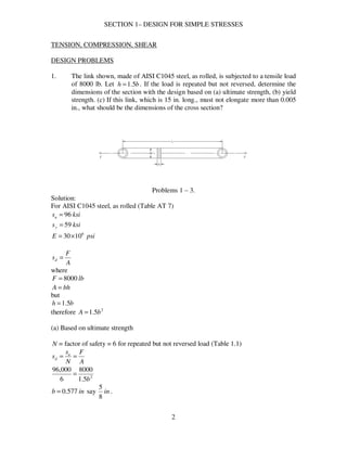
  • 1. SECTION 1– DESIGN FOR SIMPLE STRESSES 2 TENSION, COMPRESSION, SHEAR DESIGN PROBLEMS 1. The link shown, made of AISI C1045 steel, as rolled, is subjected to a tensile load of 8000 lb. Let bh 5.1= . If the load is repeated but not reversed, determine the dimensions of the section with the design based on (a) ultimate strength, (b) yield strength. (c) If this link, which is 15 in. long., must not elongate more than 0.005 in., what should be the dimensions of the cross section? Problems 1 – 3. Solution: For AISI C1045 steel, as rolled (Table AT 7) ksisu 96= ksisy 59= psiE 6 1030×= A F sd = where lbF 8000= bhA = but bh 5.1= therefore 2 5.1 bA = (a) Based on ultimate strength N = factor of safety = 6 for repeated but not reversed load (Table 1.1) A F N s s u d == 2 5.1 8000 6 000,96 b = inb 577.0= say in 8 5 .
  • 2. SECTION 1– DESIGN FOR SIMPLE STRESSES 3 inbh 16 15 5.1 == (b) Based on yield strength N = factor of safety = 3 for repeated but not reversed load (Table 1.1) A F N s s u d == 2 5.1 8000 3 000,59 b = inb 521.0= say in 16 9 . inbh 32 27 5.1 == (c) Elongation = AE FL =δ where, in005.0=δ lbF 8000= psiE 6 1030×= inL 15= 2 5.1 bA = then, AE FL =δ ( )( ) ( )( )62 10305.1 158000 005.0 × = b inb 730.0= say in 4 3 . inbh 8 1 15.1 == 2. The same as 1 except that the material is malleable iron, ASTM A47-52, grade 35 018. Solution: For malleable iron, ASTM A47-52, grade 35 018(Table AT 6) ksisu 55= ksisy 5.36= psiE 6 1025×=
  • 3. SECTION 1– DESIGN FOR SIMPLE STRESSES 4 A F sd = where lbF 8000= bhA = but bh 5.1= therefore 2 5.1 bA = (a) Based on ultimate strength N = factor of safety = 6 for repeated but not reversed load (Table 1.1) A F N s s u d == 2 5.1 8000 6 000,55 b = inb 763.0= say in 8 7 . inbh 16 5 15.1 == (b) Based on yield strength N = factor of safety = 3 for repeated but not reversed load (Table 1.1) A F N s s u d == 2 5.1 8000 3 500,36 b = inb 622.0= say in 16 11 . inbh 32 1 15.1 == (c) Elongation = AE FL =δ where, in005.0=δ lbF 8000= psiE 6 1025×= inL 15= 2 5.1 bA = then,
  • 4. SECTION 1– DESIGN FOR SIMPLE STRESSES 5 AE FL =δ ( )( ) ( )( )62 10255.1 158000 005.0 × = b inb 8.0= say in 8 7 . inbh 16 5 15.1 == 3. The same as 1 except that the material is gray iron, ASTM 30. Solution: For ASTM 30 (Table AT 6) ksisu 30= , no ys psiE 6 105.14 ×= Note: since there is no ys for brittle materials. Solve only for (a) and (c) A F sd = where lbF 8000= bhA = but bh 5.1= therefore 2 5.1 bA = (a) Based on ultimate strength N = factor of safety = 7 ~ 8 say 7.5 (Table 1.1) A F N s s u d == 2 5.1 8000 5.7 000,30 b = inb 1547.1= say in 16 3 1 . inbh 32 25 15.1 == (c) Elongation = AE FL =δ where, in005.0=δ lbF 8000= psiE 6 105.14 ×=
  • 5. SECTION 1– DESIGN FOR SIMPLE STRESSES 6 inL 15= 2 5.1 bA = then, AE FL =δ ( )( ) ( )( )62 105.145.1 158000 005.0 × = b inb 050.1= say in 16 1 1 . inbh 32 19 15.1 == 4. A piston rod, made of AISI 3140 steel, OQT 1000 F (Fig. AF 2), is subjected to a repeated, reversed load. The rod is for a 20-in. air compressor, where the maximum pressure is 125 psig. Compute the diameter of the rod using a design factor based on (a) ultimate strength, (b) yield strength. Solution: From Fig. AF 2 for AISI 3140, OQT 1000 F ksisu 5.152= ksisy 5.132= ( ) ( ) kipslbforceF 27.39270,3912520 4 2 ==== π From Table 1.1, page 20 8=uN 4=yN (a) Based on ultimate strength u u s FN A = ( )( ) 5.152 27.398 4 2 =d π ind 62.1= say in 8 5 1 (b) Based on yield strength y y s FN A = ( )( ) 5.132 27.394 4 2 =d π
  • 6. SECTION 1– DESIGN FOR SIMPLE STRESSES 7 ind 23.1= say in 4 1 1 5. A hollow, short compression member, of normalized cast steel (ASTM A27-58, 65 ksi), is to support a load of 1500 kips with a factor of safety of 8 based on the ultimate strength. Determine the outside and inside diameters if io DD 2= . Solution: ksisu 65= 8=uN kipsF 1500= ( ) ( ) 4 3 4 44 2 2222 i iiio D DDDDA πππ =−=−= ( )( ) 65 15008 4 3 2 === u ui s FND A π inDi 85.8= say in 8 7 8 inDD io 4 3 17 8 7 822 =      == 6. A short compression member with io DD 2= is to support a dead load of 25 tons. The material is to be 4130 steel, WQT 1100 F. Calculate the outside and inside diameters on the basis of (a) yield strength, (b) ultimate strength. Solution: From Table AT 7 for 4130, WQT 1100 F ksisu 127= ksisy 114= From Table 1.1 page 20, for dead load 4~3=uN , say 4 2~5.1=yN , say 2 Area, ( ) ( ) 4 3 4 44 2 2222 i iiio D DDDDA πππ =−=−= kipstonsF 5025 == (a) Based on yield strength ( )( ) 114 502 4 3 2 === y yi s FND A π
  • 7. SECTION 1– DESIGN FOR SIMPLE STRESSES 8 inDi 61.0= say in 8 5 inDD io 4 1 1 8 5 22 =      == (b) Based on ultimate strength ( )( ) 127 504 4 3 2 === u ui s FND A π inDi 82.0= say in 8 7 inDD io 4 3 1 8 7 22 =      == 7. A round, steel tension member, 55 in. long, is subjected to a maximum load of 7000 lb. (a) What should be its diameter if the total elongation is not to exceed 0.030 in? (b) Choose a steel that would be suitable on the basis of yield strength if the load is gradually applied and repeated (not reversed). Solution: (a) AE FL =δ or E FL A δ = where, lbF 7000= inL 55= in030.0=δ psiE 6 1030×= ( )( ) ( )( )6 2 1030030.0 557000 4 × == dA π ind 74.0= say in 4 3 (b) For gradually applied and repeated (not reversed) load 3=yN ( )( ) ( ) psi A FN s y y 534,47 75.0 4 70003 2 === π ksisy 48≈ say C1015 normalized condition ( ksisy 48= ) 8. A centrifuge has a small bucket, weighing 0.332 lb. with contents, suspended on a manganese bronze pin (B138-A, ½ hard) at the end of a horizontal arm. If the pin is in double shear under the action of the centrifugal force, determine the diameter
  • 8. SECTION 1– DESIGN FOR SIMPLE STRESSES 9 needed for 10,000 rpm of the arm. The center of gravity of the bucket is 12 in. from the axis of rotation. Solution: From Table AT 3, for B138-A, ½ hard ksisus 48= r g W F 2 ω= where lbW 332.0= 2 2.32 fpsg = ( ) sec1047 60 000,102 60 2 rad n === ππ ω inr 12= ( ) ( ) kipslbr g W F 3.11300,1111047 2.32 332.0 22 ==== ω From Table 1.1, page 20 4~3=N , say 4 u u s FN A = ( )( ) 48 3.114 4 2 2 =      d π for double shear ind 774.0= say in 32 25 CHECK PROBLEMS 9. The link shown is made of AISIC1020 annealed steel, with inb 4 3 = and inh 2 1 1= . (a) What force will cause breakage? (b) For a design factor of 4 based on the ultimate strength, what is the maximum allowable load? (c) If 5.2=N based on the yield strength, what is the allowable load? Problem 9.
  • 9. SECTION 1– DESIGN FOR SIMPLE STRESSES 10 Solution: For AISI C1020 annealed steel, from Table AT 7 ksisu 57= ksisy 42= (a) AsF u= 2 125.1 2 1 1 4 3 inbhA =            == ( )( ) kipsF 64125.157 == (b) u u N As F = 4=uN 2 125.1 2 1 1 4 3 inbhA =            == ( )( ) kipsF 16 4 125.157 == (c) y y N As F = 5.2=yN 2 125.1 2 1 1 4 3 inbhA =            == ( )( ) kipsF 9.18 2 125.142 == 10. A ¾-in.bolt, made of cold-finished B1113, has an effective stress area of 0.334 sq. in. and an effective grip length of 5 in. The bolt is to be loaded by tightening until the tensile stress is 80 % of the yield strength, as determined by measuring the total elongation. What should be the total elongation? Solution: E sL =δ from Table AT 7 for cold-finished B1113 ksisy 72= then, ( ) ksiss y 6.57728.080.0 === ksipsiE 000,301030 6 =×= ( )( ) in E sL 0096.0 000,30 56.57 ===δ
  • 10. SECTION 1– DESIGN FOR SIMPLE STRESSES 11 11. A 4-lb. weight is attached by a 3/8-in. bolt to a rotating arm 14-in. from the center of rotation. The axis of the bolts is normal to the plane in which the centrifugal force acts and the bolt is in double shear. At what speed will the bolt shear in two if it is made of AISI B1113, cold finish? Solution: From Table AT 7, psiksisus 000,6262 == ( ) 2 2 2209.0 8 3 4 1 2 inA =            = π Asr g W F us== 2 ω ( ) ( )( )2209.0000,6214 2.32 4 2 =ω sec74.88 rad=ω 74.88 60 2 == nπ ω rpmn 847= 12. How many ¾-in. holes could be punched in one stroke in annealed steel plate of AISI C1040, 3/16-in. thick, by a force of 60 tons? Solution: For AISI C1040, from Figure AF 1 ksisu 80= ( ) ksiksiss uus 608075.075.0 === 2 4418.0 16 3 4 3 intdA =            == ππ kipstonsF 12060 == n = number of holes ( )( ) 5 604415.0 120 === usAs F n holes 13. What is the length of a bearing for a 4-in. shaft if the load on the bearing is 6400 lb. and the allowable bearing pressure is 200 psi of the projected area? Solution: WpDL = where psip 200= inD 4=
  • 11. SECTION 1– DESIGN FOR SIMPLE STRESSES 12 lbW 6400= ( )( ) 64004200 =L inL 8= BENDING STRESSES DESIGN PROBLEMS 14. A lever keyed to a shaft is inL 15= long and has a rectangular cross section of th 3= . A 2000-lb load is gradually applied and reversed at the end as shown; the material is AISI C1020, as rolled. Design for both ultimate and yield strengths. (a) What should be the dimensions of a section at ina 13= ? (b) at inb 4= ? (c) What should be the size where the load is applied? Problem 14. Solution: For AISI C1020, as rolled, Table AT 7 ksisu 65= ksisy 49= Design factors for gradually applied and reversed load 8=uN 4=yN 12 3 th I = , moment of inertial but th 3= 36 4 h I = Moment Diagram (Load Upward)
  • 12. SECTION 1– DESIGN FOR SIMPLE STRESSES 13 Based on ultimate strength u u N s s = (a) I Fac I Mc s == 2 h c = kipslbsF 22000 == ( )( )             == 36 2 132 8 65 4 h h s inh 86.3= in h t 29.1 3 86.3 3 === say ininh 2 1 45.4 == inint 2 1 15.1 == (b) I Fbc I Mc s == 2 h c = kipslbsF 22000 == ( )( )             == 36 2 42 8 65 4 h h s inh 61.2= in h t 87.0 3 61.2 3 === say inh 3= int 1= (c)
  • 13. SECTION 1– DESIGN FOR SIMPLE STRESSES 14 413 35.4 4 3 − − = − h inh 33.2= 413 15.1 4 1 − − = − t int 78.0= say inh 625.2= or inh 8 5 2= 15. A simple beam 54 in. long with a load of 4 kips at the center is made of cast steel, SAE 080. The cross section is rectangular (let bh 3≈ ). (a) Determine the dimensions for 3=N based on the yield strength. (b) Compute the maximum deflection for these dimensions. (c) What size may be used if the maximum deflection is not to exceed 0.03 in.? Solution: For cast steel, SAE 080 (Table AT 6) ksisy 40= psiE 6 1030×=
  • 14. SECTION 1– DESIGN FOR SIMPLE STRESSES 15 From Table AT 2 Max. ( )( ) inkips FL M −=== 54 4 544 4 12 3 bh I = but bh 3= 36 4 h I = (a) I Mc N s s y y == 2 h c = ( )             = 36 2 54 3 40 4 h h inh 18.4= in h b 39.1 3 18.4 3 === say inh 2 1 4= , inin h b 2 1 15.1 3 5.4 3 ==== (b) ( )( ) ( ) ( )( ) in EI FL 0384.0 12 5.45.1 103048 544000 48 3 6 33 =       × ==δ (c)       = 36 48 4 3 h E FL δ ( )( ) ( ) ( )( )46 3 103048 36544000 03.0 h× = inh 79.4= in h b 60.1 3 79.4 3 === say ininh 4 1 525.5 == , inin h b 4 3 175.1 3 25.5 3 ====
  • 15. SECTION 1– DESIGN FOR SIMPLE STRESSES 16 16. The same as 15, except that the beam is to have a circular cross section. Solution: (a) I Mc N s s y y == 64 4 d I π = 2 d c = 34 32 64 2 d M d d M s ππ =             = ( ) 3 5432 3 40 dπ = ind 46.3= say ind 2 1 3= (b) EI FL 48 3 =δ 64 4 d I π = ( ) ( )( ) ( )( )( ) in dE FL 0594.0 5.3103048 54400064 48 64 46 3 4 3 = × == ππ δ (c) ( )4 3 48 64 dE FL π δ = ( )( ) ( )( ) 46 3 103048 54400064 03.0 dπ× = ind 15.4= say ind 4 1 4= 17. A simple beam, 48 in. long, with a static load of 6000 lb. at the center, is made of C1020 structural steel. (a) Basing your calculations on the ultimate strength, determine the dimensions of the rectangular cross section for bh 2= . (b) Determine the dimensions based on yield strength. (c) Determine the dimensions using the principle of “limit design.”
  • 16. SECTION 1– DESIGN FOR SIMPLE STRESSES 17 Solution: From Table AT 7 and Table 1.1 ksisu 65= ksisy 48= 4~3=uN , say 4 2~5.1=yN , say 2 ( )( ) kipsin FL M −=== 72 4 486 4 I Mc s = 2 h c = 12 3 bh I = but 2 h b = 24 4 h I = 34 12 24 2 h M h h M s =       = (a) Based on ultimate strength 3 12 h M N s s u u == ( ) 3 7212 4 65 h = inh 76.3=
  • 17. SECTION 1– DESIGN FOR SIMPLE STRESSES 18 in h b 88.1 2 76.3 2 === say ininh 4 3 375.3 == , inin h b 8 7 1875.1 2 75.3 2 ==== (b) Based on yield strength 3 12 h M N s s y y == ( ) 3 7212 2 48 h = inh 30.3= in h b 65.1 2 30.3 2 === say ininh 2 1 35.3 == , inin h b 4 3 175.1 2 5.3 2 ==== (c) Limit design (Eq. 1.6) 4 2 bh sM y= ( ) 4 2 4872 2 h h       = inh 29.2= in h b 145.1 2 29.2 2 === say ininh 2 1 25.2 == , inin h b 4 1 125.1 2 5.2 2 ==== 18. The bar shown is subjected to two vertical loads, 1F and 2F , of 3000 lb. each, that are inL 10= apart and 3 in. ( a ,d ) from the ends of the bar. The design factor is 4 based on the ultimate strength; bh 3= . Determine the dimensions h and b if the bar is made of (a) gray cast iron, SAE 111; (b) malleable cast iron, ASTM A47- 52, grade 35 018; (c) AISI C1040, as rolled (Fig. AF 1). Sketch the shear and moment diagrams approximately to scale.
  • 18. SECTION 1– DESIGN FOR SIMPLE STRESSES 19 Problems18, 19. Solution: lbRRFF 30002121 ==== Moment Diagram ( )( ) inkipsinlbsaRM −=−=== 99000330001 N = factor of safety = 4 based on us 12 3 bh I = 2 h c = 3612 3 4 3 h h h I =       = (a) For gray cast iron, SAE 111 ksisu 30= , Table AT 6 34 18 36 2 h M h h M I Mc N s s u =             === ( ) 3 918 4 30 h s == inh 78.2= in h b 93.0 3 78.2 3 === say inh 5.3= , inb 1= (b) For malleable cast iron, ASTM A47-52, grade 35 018
  • 19. SECTION 1– DESIGN FOR SIMPLE STRESSES 20 ksisu 55= , Table AT 6 34 18 36 2 h M h h M I Mc N s s u =             === ( ) 3 918 4 55 h s == inh 28.2= in h b 76.0 3 28.2 3 === say inh 4 1 2= , inb 4 3 = (c) For AISI C1040, as rolled ksisu 90= , Fig. AF 1 34 18 36 2 h M h h M I Mc N s s u =             === ( ) 3 918 4 90 h s == inh 93.1= in h b 64.0 3 93.1 3 === say inh 8 7 1= , inb 8 5 = 19. The same as 18, except that 1F acts up ( 2F acts down). Solution: [ ]∑ = 0AM lbRR 187521 ==
  • 20. SECTION 1– DESIGN FOR SIMPLE STRESSES 21 Shear Diagram Moment Diagram =M maximum moment = 5625 lb-in = 5.625 kips-in (a) For gray cast iron 3 18 h M N s s u == ( ) 3 625.518 4 30 h = inh 38.2= in h b 79.0 3 38.2 3 === say inh 4 1 2= , inb 4 3 = (b) For malleable cast iron 3 18 h M N s s u == ( ) 3 625.518 4 55 h = inh 95.1= in h b 65.0 3 95.1 3 === say inh 8 7 1= , inb 8 5 =
  • 21. SECTION 1– DESIGN FOR SIMPLE STRESSES 22 (c) For AISI C1040, as rolled 3 18 h M N s s u == ( ) 3 625.518 4 90 h = inh 65.1= in h b 55.0 3 65.1 3 === say inh 2 1 1= , inb 2 1 = 20. The bar shown, supported at A and B , is subjected to a static load F of 2500 lb. at 0=θ . Let ind 3= , inL 10= and bh 3= . Determine the dimensions of the section if the bar is made of (a) gray iron, SAE 110; (b) malleable cast iron, ASTM A47-52, grade 32 510; (c) AISI C1035 steel, as rolled. (d) For economic reasons, the pins at A, B, and C are to be the same size. What should be their diameter if the material is AISI C1035, as rolled, and the mounting is such that each is in double shear? Use the basic dimensions from (c) as needed. (e) What sectional dimensions would be used for the C1035 steel if the principle of “limit design” governs in (c)? Problems 20, 21. Solution:
  • 22. SECTION 1– DESIGN FOR SIMPLE STRESSES 23 [ ]∑ = 0AM ( )2500133 =BR lbRB 833,10= [ ]∑ = 0BM ( )2500103 =AR lbRA 8333= Shear Diagram Moment Diagram ( )( ) inkipsinlbM −=−== 25000,25102500 bh 3= 12 3 bh I = 36 4 h I = 2 h c = 34 18 36 2 h M h h M I Mc s =             == (a) For gray cast iron, SAE 110 ksisu 20= , Table AT 6 6~5=N , say 6 for cast iron, dead load 3 18 h M N s s u == ( ) 3 2518 6 20 h =
  • 23. SECTION 1– DESIGN FOR SIMPLE STRESSES 24 inh 13.5= in h b 71.1 3 == say inh 4 1 5= , inb 4 3 1= (b) For malleable cast iron, ASTM A47-32 grade 32510 ksisu 52= , ksisy 34= 4~3=N , say 4 for ductile, dead load 3 18 h M N s s u == ( ) 3 2518 4 52 h = inh 26.3= in h b 09.1 3 == say inh 4 3 3= , inb 4 1 1= (c) For AISI C1035, as rolled ksisu 85= , ksisy 55= 4=N , based on ultimate strength 3 18 h M N s s u == ( ) 3 2518 4 85 h = inh 77.2= in h b 92.0 3 == say inh 3= , inb 1= (d) For AISI C1035, as rolled ksissu 64= 4=N , kipsRB 833.10= A R N s s Bsu s == 22 24 2 DDA ππ =      = 2 2 833.10 4 64 D ss π == inD 657.0=
  • 24. SECTION 1– DESIGN FOR SIMPLE STRESSES 25 say inD 16 11 = (e) Limit Design 4 2 bh sM y= For AISI C1035 steel, ksisy 55= 3 h b = ( ) 4 3 5525 2 h h M       == inh 76.1= in h b 59.0 3 == say ininh 8 7 1875.1 == , inb 8 5 = 21. The same as 20, except that o 30=θ . Pin B takes all the horizontal thrust. Solution: θcosFFV = [ ]∑ = 0AM VB FR 133 = ( ) 30cos2500133 =BR lbRB 9382= [ ]∑ = 0BM VA FR 103 = ( ) 30cos2500103 =AR lbRA 7217= Shear Diagram
  • 25. SECTION 1– DESIGN FOR SIMPLE STRESSES 26 Moment Diagram ( )( ) inkipsinlbM −=−== 65.21650,21102165 3 18 h M s = (a) For gray cast iron, SAE 110 ksisu 20= , Table AT 6 6~5=N , say 6 for cast iron, dead load 3 18 h M N s s u == ( ) 3 65.2118 6 20 h = inh 89.4= in h b 63.1 3 == say inh 4 1 5= , inb 4 3 1= (b) For malleable cast iron, ASTM A47-32 grade 32510 ksisu 52= , ksisy 34= 4~3=N , say 4 for ductile, dead load 3 18 h M N s s u == ( ) 3 65.2118 4 52 h = inh 11.3= in h b 04.1 3 == say inh 3= , inb 1= (c) For AISI C1035, as rolled ksisu 85= , ksisy 55= 4=N , based on ultimate strength
  • 26. SECTION 1– DESIGN FOR SIMPLE STRESSES 27 3 18 h M N s s u == ( ) 3 65.2118 4 85 h = inh 64.2= in h b 88.0 3 == say inh 8 5 2= , inb 8 7 = (d) For AISI C1035, as rolled ksissu 64= 4=N , lbRBV 9382= lbFFR HBH 125030sin2500sin ==== θ ( ) ( )22222 12509382 +=+= BHBVB RRR lbRB 9465= A R N s s Bsu s == 22 24 2 DDA ππ =      = 2 2 465.9 4 64 D ss π == inD 614.0= say inD 8 5 = (e) Limit Design 4 2 bh sM y= For AISI C1035 steel, ksisy 55= 3 h b = ( ) 4 3 5565.21 2 h h M       == inh 68.1= in h b 56.0 3 == say ininh 8 7 1875.1 == , inb 8 5 =
  • 27. SECTION 1– DESIGN FOR SIMPLE STRESSES 28 22. A cast-iron beam, ASTM 50, as shown, is 30 in. long and supports two gradually applied, repeated loads (in phase), one of 2000 lb. at ine 10= from the free end, and one of 1000 lb at the free end. (a) Determine the dimensions of the cross section if acb 3≈= . (b) The same as (a) except that the top of the tee is below. Problem 22. Solution: For cast iron, ASTM 50 ksisu 50= , ksisuc 164= For gradually applied, repeated load 8~7=N , say 8 ( )edFdFM ++= 21 where: lbF 20001 = lbF 10002 = ind 201030 =−= ined 30=+ ( )( ) ( )( ) inkipsinlbM −=−=+= 70000,70301000202000 I Mc s = Solving for I , moment of inertia ( )( ) ( )( ) ( )( ) ( )( )[ ]yaaaa a aa a aa 33 2 5 3 2 3 +=      +      2 3a y =
  • 28. SECTION 1– DESIGN FOR SIMPLE STRESSES 29 ( )( ) ( )( )( ) ( )( ) ( )( )( ) 2 17 3 12 3 3 12 3 4 2 3 2 3 a aaa aa aaa aa I =+++= (a) 2 3a ct = 2 5a cc = Based on tension I Mc N s s tu t == ( )             = 2 17 2 3 70 8 50 4 a a ina 255.1= Based on compression I Mc N s s cuc c == ( )             = 2 17 2 5 70 8 164 4 a a ina 001.1= Therefore ina 255.1= Or say ina 4 1 1= And ( ) inacb 75.325.133 ====
  • 29. SECTION 1– DESIGN FOR SIMPLE STRESSES 30 Or incb 4 3 3== (b) If the top of the tee is below 2 5a ct = 2 3a cc = 2 17 4 a I = inkipsM −= 70 Based on tension I Mc N s s tu t == ( )             = 2 17 2 5 70 8 50 4 a a ina 488.1= Based on compression I Mc N s s cuc c == ( )             = 2 17 2 3 70 8 164 4 a a ina 845.0= Therefore ina 488.1= Or say ina 2 1 1= And inacb 2 1 43 === CHECK PROBLEMS
  • 30. SECTION 1– DESIGN FOR SIMPLE STRESSES 31 23. An I-beam is made of structural steel, AISI C1020, as rolled. It has a depth of 3 in. and is subjected to two loads; 1F and 12 2FF = ; 1F is 5 in. from one end and 2F is 5 in. from the other ends. The beam is 25 in. long; flange width is inb 509.2= ; 4 9.2 inIx = . Determine (a) the approximate values of the load to cause elastic failure, (b) the safe loads for a factor of safety of 3 based on the yield strength, (c) the safe load allowing for flange buckling (i1.24), (f) the maximum deflection caused by the safe loads. Problems 23 – 25. Solution: [ ]∑ = 0AM ( ) BRFF 252205 11 =+ 18.1 FRB = [ ]∑ = 0VF BA RRFF +=+ 11 2 111 2.18.13 FFFRA =−= Shear Diagram Moment Diagram
  • 31. SECTION 1– DESIGN FOR SIMPLE STRESSES 32 19FM = = maximum moment For AISI C1020, as rolled ksisy 48= (a) I Mc sy = where in d c 5.1 2 3 2 === ( )( ) 9.2 5.19 48 1F sy == kipsF 31.101 = kipsFF 62.202 12 == (b) I Mc N s s y == ( )( ) 9.2 5.19 3 48 1F s == kipsF 44.31 = kipsFF 88.62 12 == (c) 1596.9 509.2 25 <== b L (page 34) ksisc 20= ( page 34, i1.24) I Mc sc = ( )( ) 9.2 5.19 20 1F = kipsF 30.41 = kipsFF 60.82 12 == (d) For maximum deflection, by method of superposition, Table AT 2 ( ) 2 3 max 33     ′+′ = bLa EIL bF y , ba ′> or ( ) 2 3 max 33     +′ = aLb EIL Fa y , ab >′
  • 32. SECTION 1– DESIGN FOR SIMPLE STRESSES 33 maxy caused by 1F ( ) 2 3 1111 max 331     +′ = aLb EIL aF y , 11 ab >′ where ksiE 000,30= ina 51 = inb 201 =′ inL 25= 4 9.2 inI = ( ) ( )( )( ) ( ) 1 2 3 1 max 0022.0 3 52520 259.2000,303 5 1 F F y =    + = maxy caused by 2F ( ) 2 3 2222 max 332     ′+′ = bLa EIL bF y , 22 ba ′> where inb 52 =′ ina 202 = ( ) ( )( )( ) ( ) 1 2 3 1 max 0043.0 3 52520 259.2000,303 52 2 F F y =    + = Total deflection = δ 111maxmax 0065.00043.0022.021 FFFyy =+=+=δ Deflection caused by the safe loads in (a) ( ) ina 067.031.100065.0 ==δ Deflection caused by the safe loads in (b) ( ) inb 022.044.30065.0 ==δ Deflection caused by the safe loads in (c) ( ) inc 028.030.40065.0 ==δ 24. The same as 23, except that the material is aluminum alloy, 2024-T4, heat treated. Solution: For aluminum alloy, 2024-T4, heat treated ksisy 47= (a) I Mc sy =
  • 33. SECTION 1– DESIGN FOR SIMPLE STRESSES 34 ( )( ) 9.2 5.19 47 1F sy == kipsF 10.101 = kipsFF 20.202 12 == (b) I Mc N s s y == ( )( ) 9.2 5.19 3 47 1F s == kipsF 36.31 = kipsFF 72.62 12 == (c) 1596.9 509.2 25 <== b L (page 34) ksisc 20= ( page 34, i1.24) I Mc sc = ( )( ) 9.2 5.19 20 1F = kipsF 30.41 = kipsFF 60.82 12 == (d) Total deflection = δ 111maxmax 0065.00043.0022.021 FFFyy =+=+=δ Deflection caused by the safe loads in (a) ( ) ina 066.010.100065.0 ==δ Deflection caused by the safe loads in (b) ( ) inb 022.036.30065.0 ==δ Deflection caused by the safe loads in (c) ( ) inc 028.030.40065.0 ==δ 25. A light I-beam is 80 in. long, simply supported, and carries a static load at the midpoint. The cross section has a depth of ind 4= , a flange width of inb 66.2= , and 4 0.6 inIx = (see figure). (a) What load will the beam support if it is made of C1020, as-rolled steel, and flange buckling (i1.24) is considered? (b) Consider the stress owing to the weight of the beam, which is 7.7 lb/ft, and decide whether or not the safe load should be less.
  • 34. SECTION 1– DESIGN FOR SIMPLE STRESSES 35 Solution: (a) For C1020, as rolled, ksisu 65= Consider flange buckling 30 66.2 80 == b L since 4015 << b L ( ) ksi b L sc 15 1800 30 1 5.22 18001 5.22 22 = + =       + = I Mc s = in d c 2 2 4 2 === From Table AT 2 ( ) F FFL M 20 4 80 4 === I Mc ss c == ( )( ) 6 220 15 F = kipsF 25.2= , safe load (b) Considering stress owing to the weight of the beam add’l 8 2 wL M = (Table AT 2) where ftlbw 7.7=
  • 35. SECTION 1– DESIGN FOR SIMPLE STRESSES 36 add’l ( ) inkipsinlb wL M −=−=      == 513.0513 8 80 12 7.7 8 22 513.020 += FM = total moment I Mc ss c == ( )( ) 6 2513.020 15 + = F kipsF 224.2= Therefore, the safe load should be less. 26. What is the stress in a band-saw blade due to being bent around a 13 ¾-in. pulley? The blade thickness is 0.0265 in. (Additional stresses arise from the initial tension and forces of sawing.) Solution: in t c 01325.00265.0 2 === inr 76325.1301325.075.13 =+= Using Eq. (1.4) page 11 (Text) r Ec s = where psiE 6 1030×= ( )( ) psis 881,28 76325.13 01325.01030 6 = × = 27. A cantilever beam of rectangular cross section is tapered so that the depth varies uniformly from 4 in. at the fixed end to 1 in. at the free end. The width is 2 in. and the length 30 in. What safe load, acting repeated with minor shock, may be applied to the free end? The material is AISI C1020, as rolled. Solution: For AISI C1020, as rolled ksisu 65= (Table AT 7) Designing based on ultimate strength, 6=N , for repeated, minor shock load
  • 36. SECTION 1– DESIGN FOR SIMPLE STRESSES 37 ksi N s s u 8.10 6 65 === Loading Diagram x h 1 30 14 − = − 110.0 += xh 12 3 wh I = 2 h c = FxM = ( ) ( )2223 110.0 33 2 6 12 2 + ===             == x Fx h Fx h Fx wh h Fx I Mc s Differentiating with respect to x then equate to zero to solve for x giving maximum stress. ( ) ( ) ( )( )( ) ( ) 0 110.0 10.0110.021110.0 3 4 2 =      + +−+ = x xxx F dx ds ( ) 010.02110.0 =−+ xx inx 10= ( ) inh 211010.0 =+= 2 3 h Fx N s s u == ( ) ( )2 2 103 8.10 F = kipsF 44.1= TORSIONAL STRESSES DESIGN PROBLEMS
  • 37. SECTION 1– DESIGN FOR SIMPLE STRESSES 38 28. A centrifugal pump is to be driven by a 15-hp electric motor at 1750 rpm. What should be the diameter of the pump shaft if it is made of AISI C1045 as rolled? Consider the load as gradually repeated. Solution: For C1045 as rolled, ksisy 59= ksisus 72= Designing based on ultimate strength N s s us = , 6=N (Table 1.1) ksis 12 6 72 == Torque, ( ) ( ) kipsinlbinlbft n hp T −=−=−=== 540.054045 17502 15000,33 2 000,33 ππ For diameter, 3 16 d T s π = ( ) 3 540.016 12 dπ = ind 612.0= say ind 8 5 = 29. A shaft in torsion only is to transmit 2500 hp at 570 rpm with medium shocks. Its material is AISI 1137 steel, annealed. (a) What should be the diameter of a solid shaft? (b) If the shaft is hollow, io DD 2= , what size is required? (c) What is the weight per foot of length of each of these shafts? Which is the lighter? By what percentage? (d) Which shaft is the more rigid? Compute the torsional deflection of each for a length of 10 ft. Solution: ( ) ( ) kipsinlbft n hp T −=−=== 276036,23 5702 2500000,33 2 000,33 ππ For AISI 1137, annealed ksisy 50= (Table AT 8) ksiss yys 306.0 == Designing based on yield strength 3=N for medium shock, one direction
  • 38. SECTION 1– DESIGN FOR SIMPLE STRESSES 39 Design stress ksi N s s ys 10 3 30 === (a) Let D = shaft diameter J Tc s = 32 4 D J π = 2 D c = 3 16 D T s π = ( ) 3 27616 10 Dπ = inD 20.5= say inD 4 1 5= (b) ( ) ( )[ ] 32 15 32 2 32 44444 iiiio DDDDD J πππ = − = − = i io D DD c === 2 2 2 34 15 32 32 15 ii i D T D TD s ππ =       = ( ) 3 15 27632 10 iDπ = inDi 66.2= inDD io 32.52 == say inDi 8 5 2= inDo 4 1 5= (c) Density, 3 284.0 inlb=ρ (Table AT 7)
  • 39. SECTION 1– DESIGN FOR SIMPLE STRESSES 40 For solid shaft =w weight per foot of length ( )( ) ftlbDDw 8.7325.5284.033 4 12 222 ===      = ππρ π ρ For hollow shaft ( ) ( ) ( )( ) ( )[ ] ftlbDDDDw ioio 3.55625.225.5284.033 4 12 222222 =−=−=−      = ππρ π ρ Therefore hollow shaft is lighter Percentage lightness = ( ) %5.33%100 3.55 3.558.73 = − (d) Torsional Deflection JG TL =θ where inftL 12010 == ksiG 3 105.11 ×= For solid shaft, 32 4 D J π = ( )( ) ( ) ( ) ( ) o 2.2 180 039.0039.0 105.1125.5 32 120276 34 =      == ×      = ππ θ rad For hollow shaft, ( ) 32 44 io DD J − = π ( )( ) ( ) ( )[ ]( ) ( ) o 4.2 180 041.0041.0 105.11625.225.5 32 120276 344 =      == ×−      = ππ θ rad Therefore, solid shaft is more rigid, oo 4.22.2 < 30. The same as 29, except that the material is AISI 4340, OQT 1200 F. Solution: ( ) ( ) kipsinlbft n hp T −=−=== 276036,23 5702 2500000,33 2 000,33 ππ For AISI 4340, OQT 1200 F ksisy 130= ( ) ksiss yys 781306.06.0 === Designing based on yield strength
  • 40. SECTION 1– DESIGN FOR SIMPLE STRESSES 41 3=N for mild shock Design stress ksi N s s ys 26 3 78 === (a) Let D = shaft diameter J Tc s = 32 4 D J π = 2 D c = 3 16 D T s π = ( ) 3 27616 26 Dπ = inD 78.3= say inD 4 3 3= (b) ( ) ( )[ ] 32 15 32 2 32 44444 iiiio DDDDD J πππ = − = − = i io D DD c === 2 2 2 34 15 32 32 15 ii i D T D TD s ππ =       = ( ) 3 15 27632 26 iDπ = inDi 93.1= inDD io 86.32 == say inDi 2= inDo 4= (c) Density, 3 284.0 inlb=ρ (Table AT 7)
  • 41. SECTION 1– DESIGN FOR SIMPLE STRESSES 42 For solid shaft =w weight per foot of length ( )( ) ftlbDDw 6.3775.3284.033 4 12 222 ===      = ππρ π ρ For hollow shaft ( ) ( ) ( )( ) ( )[ ] ftlbDDDDw ioio 1.3224284.033 4 12 222222 =−=−=−      = ππρ π ρ Therefore hollow shaft is lighter Percentage lightness = ( ) %1.17%100 1.32 1.326.37 = − (d) Torsional Deflection JG TL =θ where inftL 12010 == ksiG 3 105.11 ×= For solid shaft, 32 4 D J π = ( )( ) ( ) ( ) ( ) o 48.8 180 148.0148.0 105.1175.3 32 120276 34 =      == ×      = ππ θ rad For hollow shaft, ( ) 32 44 io DD J − = π ( )( ) ( ) ( )[ ]( ) ( ) o 99.6 180 122.0122.0 105.1124 32 120276 344 =      == ×−      = ππ θ rad Therefore, hollow shaft is more rigid, oo 48.899.6 < . 31. A steel shaft is transmitting 40 hp at 500 rpm with minor shock. (a) What should be its diameter if the deflection is not to exceed 1o in D20 ? (b) If deflection is primary what kind of steel would be satisfactory? Solution: (a) ( ) ( ) kipsinlbft n hp T −=−=== 04.5420 5002 40000,33 2 000,33 ππ ksiG 3 105.11 ×= DL 20=
  • 42. SECTION 1– DESIGN FOR SIMPLE STRESSES 43 rad 180 1 π θ == o JG TL =θ ( )( ) ( )3 4 105.11 32 2004.5 180 ×      = D D π π inD 72.1= say inD 4 3 1= (b) ( ) ( ) ksi D T s 8.4 75.1 04.51616 33 === ππ Based on yield strength 3=N ( )( ) ksiNssys 4.148.43 === ksi s s ys y 24 6.0 4.14 6.0 === Use C1117 normalized steel ksisy 35= 32. A square shaft of cold-finish AISI 1118 transmits a torsional moment of 1200 in- lb. For medium shock, what should be its size? Solution: For AISI 1118 cold-finish ksisy 75= ksiss yys 456.0 == 3=N for medium shock Z T N s s ys ′ == where, bh = 9 2 9 2 32 bhb Z ==′ (Table AT 1) kipsinlbinT −=−= 2.11200 ( ) 3 2 92.1 3 45 b s == inhb 71.0== say inhb 4 3 ==
  • 43. SECTION 1– DESIGN FOR SIMPLE STRESSES 44 CHECK PROBLEMS 33. A punch press is designed to exert a force sufficient to shear a 15/16-in. hole in a ½-in. steel plate, AISI C1020, as rolled. This force is exerted on the shaft at a radius of ¾-in. (a) Compute the torsional stress in the 3.5-in. shaft (bending neglected). (b) What will be the corresponding design factor if the shaft is made of cold-rolled AISI 1035 steel (Table AT 10)? Considering the shock loading that is characteristics of this machine, do you thick the design is safe enough? Solution: For AISI C1020, as rolled ksisus 49= ( )DtsF us π= where inD 16 15 = int 2 1 = ( ) kipsF 2.72 2 1 16 15 49 =            = π FrT = where inr 4 3 = ( ) kipsinT −=      = 2.54 4 3 2.72 (a) 3 16 d T s π = where ind 5.3= ( ) ( ) ksis 44.6 5.3 2.5416 3 == π (b) For AISI 1035 steel, ksisus 64= for shock loading, traditional factor of safety, 15~10=N Design factor , 94.9 44.6 64 === s s N us , the design is safe ( 10≈N ) 34. The same as 33, except that the shaft diameter is 2 ¾ in. Solution:
  • 44. SECTION 1– DESIGN FOR SIMPLE STRESSES 45 ind 75.2= (a) 3 16 d T s π = ( ) ( ) ksis 3.13 75.2 2.5416 3 == π (b) For AISI 1035 steel, ksisus 64= for shock loading, traditional factor of safety, 15~10=N Design factor , 8.4 3.13 64 === s s N us , the design is not safe ( 10<N ) 35. A hollow annealed Monel propeller shaft has an external diameter of 13 ½ in. and an internal diameter of 6 ½ in.; it transmits 10,000 hp at 200 rpm. (a) Compute the torsional stress in the shaft (stress from bending and propeller thrust are not considered). (b) Compute the factor of safety. Does it look risky? Solution: For Monel shaft, ksisus 98= (Table AT 3) 4~3=N , for dead load, based on ultimate strength (a) J Tc s = ( ) ( ) ( )[ ] 4 4444 3086 32 5.65.13 32 in DD J io = − = − = ππ in D c o 75.6 2 5.13 2 === ( ) ( ) kipsinlbft n hp T −=−=== 3152606,262 2002 000,10000,33 2 000,33 ππ ( )( ) ksis 9.6 3086 75.63152 == (b) Factor of safety, 2.14 9.6 98 === s s N us , not risky
  • 45. SECTION 1– DESIGN FOR SIMPLE STRESSES 46 STRESS ANALYSIS DESIGN PROBLEMS 36. A hook is attached to a plate as shown and supports a static load of 12,000 lb. The material is to be AISI C1020, as rolled. (a) Set up strength equations for dimensions d , D , h , and t . Assume that the bending in the plate is negligible. (b) Determine the minimum permissible value of these dimensions. In estimating the strength of the nut, let dD 2.11 = . (c) Choose standard fractional dimensions which you think would be satisfactory. Problems 36 – 38. Solution: s = axial stress ss = shear stress (a) 2 2 4 4 1 d F d F s ππ == Equation (1) s F d π 4 =
  • 46. SECTION 1– DESIGN FOR SIMPLE STRESSES 47 ( ) ( ) ( )[ ] ( )22222 1 2 2 1 2 44.1 4 2.1 44 4 1 dD F dD F DD F DD F s − = − = − = − = ππππ Equation (2) 2 44.1 4 d s F D += π dh F hD F ss ππ 2.11 == Equation (3) sds F h π2.1 = Dt F ss π = Equation (4) sDs F t π = (b) Designing based on ultimate strength, Table AT 7, AISI C1020, as rolled ksisu 65= ksisus 49= 4~3=N say 4, design factor for static load ksi N s s u 16 4 65 === ksi N s s us s 12 4 49 === kipslbF 12000,12 == From Equation (1) ( ) ( ) in s F d 98.0 16 1244 === ππ From Equation (2) ( ) ( ) ( ) ind s F D 53.198.044.1 16 124 44.1 4 22 =+=+= ππ From Equation (3) ( )( ) in ds F h s 27.0 1298.02.1 12 2.1 === ππ From Equation (4) ( )( ) in Ds F t s 21.0 1253.1 12 === ππ
  • 47. SECTION 1– DESIGN FOR SIMPLE STRESSES 48 (c) Standard fractional dimensions ind 1= inD 2 1 1= inh 4 1 = int 4 1 = 37. The same as 36, except that a shock load of 4000 lb. is repeatedly applied. Solution: (a) Same as 36. (b) 15~10=N for shock load, based on ultimate strength say 15=N , others the same. ksi N s s u 4 15 65 === ksi N s s us s 3 15 49 === kipslbF 44000 == From Equation (1) ( ) ( ) in s F d 13.1 4 444 === ππ From Equation (2) ( ) ( ) ( ) ind s F D 76.113.144.1 4 44 44.1 4 22 =+=+= ππ From Equation (3) ( )( ) in ds F h s 31.0 313.12.1 4 2.1 === ππ From Equation (4) ( )( ) in Ds F t s 24.0 376.1 4 === ππ
  • 48. SECTION 1– DESIGN FOR SIMPLE STRESSES 49 (c) Standard fractional dimensions ind 8 1 1= inD 4 3 1= inh 8 3 = int 4 1 = 38. The connection between the plate and hook, as shown, is to support a load F . Determine the value of dimensions D , h , and t in terms of d if the connection is to be as strong as the rod of diameter d . Assume that dD 2.11 = , uus ss 75.0= , and that bending in the plate is negligible. Solution: 2 4 1 d F s π = sdF 2 4 1 π= (1)       = N s dF u2 4 1 π
  • 49. SECTION 1– DESIGN FOR SIMPLE STRESSES 50 ( ) ( )222 1 2 44.1 4 1 4 1 dD F DD F s − = − = ππ ( )sdDF 22 44.1 4 1 −= π (2) ( )       −= N s dDF u22 44.1 4 1 π dh F hD F ss ππ 2.11 == sdhsF π2.1=       =      = N s dh N s dhF uus 75.0 2.12.1 ππ (3)       = N s dhF u5 9.0 π Dt F ss π = sDtsF π=       =      = N s Dt N s DtF uus 75.0 ππ (4)       = N s DtF u π75.0 Equate (2) and (1) ( )       =      −= N s d N s dDF uu 222 4 1 44.1 4 1 ππ 22 44.2 dD = dD 562.1= Equate (3) and (1)       =      = N s d N s dhF uu 2 4 1 9.0 ππ ( ) d d h 278.0 9.04 == Equate (4) and (1)       =      = N s d N s DtF uu 2 4 1 75.0 ππ ( )( )       =      = N s d N s tdF uu 2 4 1 562.175.0 ππ ( )( ) d d t 214.0 562.175.04 ==
  • 50. SECTION 1– DESIGN FOR SIMPLE STRESSES 51 39. (a) For the connection shown, set up strength equations representing the various methods by which it might fail. Neglect bending effects. (b) Design this connection for a load of 2500 lb. Both plates and rivets are of AISI C1020, as rolled. The load is repeated and reversed with mild shock. Make the connection equally strong on the basis of yield strengths in tension, shear, and compression. Problems 39, 40 Solution: (a)       = 2 4 1 5 D F ss π Equation (1) ss F D π5 4 = ( )Dbt F s 2− = Equation (2) D ts F b 2+= Dt F s 5 = Equation (3) Ds F t 5 = (b) For AISI C1020, as rolled ksisy 48= (Table AT 7) ksiss yys 286.0 == 4=N for repeated and reversed load (mild shock) based on yield strength ksis 12 4 48 == ksiss 7 4 28 == From Equation (1)
  • 51. SECTION 1– DESIGN FOR SIMPLE STRESSES 52 ss F D π5 4 = where kipslbF 5.22500 == ( ) ( ) in s F D s 30.0 75 5.24 5 4 === ππ say in 16 5 From Equation (3) ( ) in Ds F t 13.0 12 16 5 5 5.2 5 =       == say in 32 5 From Equation (2) ( ) inD ts F b 96.1 16 5 2 12 32 5 5.2 2 =      +       =+= say in2 40. The same as 39, except that the material is 2024-T4, aluminum alloy. Solution: (a) Same as 39. (b) ) For 2024-T4, aluminum alloy ksisy 47= (Table AT 3) ksiss yys 2555.0 == 4=N for repeated and reversed load (mild shock) based on yield strength ksis 12 4 47 == ksiss 6 4 25 == From Equation (1) ss F D π5 4 = where kipslbF 5.22500 == ( ) ( ) in s F D s 33.0 65 5.24 5 4 === ππ say in 8 3 From Equation (3)
  • 52. SECTION 1– DESIGN FOR SIMPLE STRESSES 53 ( ) in Ds F t 11.0 12 8 3 5 5.2 5 =       == say in 8 1 From Equation (2) ( ) inD ts F b 42.2 8 3 2 12 8 1 5.2 2 =      +       =+= say in 2 1 2 41. (a) For the connection shown, set up strength equations representing the various methods by which it might fail. (b) Design this connection for a load of 8000 lb. Use AISI C1015, as rolled, for the rivets, and AISI C1020, as rolled, for the plates. Let the load be repeatedly applied with minor shock in one direction and make the connection equally strong on the basis of ultimate strengths in tension, shear, and compression. Problem 41. Solution: (a) ( )Dbt F sP − = or ( )Dbt F sP 2 4 3 − = Equation (1) ( )2 4 1 4 2       = D F ssR π Equation (2)
  • 53. SECTION 1– DESIGN FOR SIMPLE STRESSES 54 Dt F sR 4 = Equation (3) (b) For AISI C1015, as rolled ksisuR 61= , ksiss uRusR 4575.0 == For AISI C1020, as rolled ksisuP 65= 6=N , based on ultimate strength ksi N s s uP P 8.10 6 65 === ksi N s s uR R 1.10 6 61 === ksi N s s usR sR 5.7 6 45 === kipslbF 88000 == Solving for D 2 2 D F ssR π = ( ) in s F D sR 412.0 5.72 8 2 === ππ say in 16 7 Solving for t Dt F sR 4 = ( ) in Ds F t R 453.0 1.10 16 7 4 8 4 =       == say in 2 1 Solving for b Using ( )Dbt F sP − = ( ) inD ts F b P 92.1 16 7 8.10 2 1 8 =+       =+= say in2 Using ( )Dbt F sP 2 4 3 − =
  • 54. SECTION 1– DESIGN FOR SIMPLE STRESSES 55 ( ) ( ) inD ts F b P 99.1 16 7 2 8.10 2 1 4 83 2 4 3 =      +       =+= say in2 Therefore inb 2= inD 16 7 = int 2 1 = 42. Give the strength equations for the connection shown, including that for the shear of the plate by the cotter. Problems 42 – 44. Solution: Axial Stresses 2 12 1 4 4 1 D F D F s ππ == Equation (1) ( )eDL F s 2− = Equation (2)
  • 55. SECTION 1– DESIGN FOR SIMPLE STRESSES 56 eD F s 2 = Equation (3) ( ) ( )2 2 2 2 2 2 4 4 1 Da F Da F s − = − = ππ Equation (4) eDD F eDD F s 2 2 2 2 2 2 4 4 4 1 − = − = ππ Equation (5) Shear Stresses eb F ss 2 = Equation (6) ( )teDL F ss +− = 22 Equation (7)
  • 56. SECTION 1– DESIGN FOR SIMPLE STRESSES 57 at F ss π = Equation (8) mD F ss 1π = Equation (9) hD F ss 22 = Equation (10) 43. A steel rod, as-rolled AISI C1035, is fastened to a 7/8-in., as-rolled C1020 plate by means of a cotter that is made of as-rolled C1020, in the manner shown. (a) Determine all dimensions of this joint if it is to withstand a reversed shock load kipsF 10= , basing the design on yield strengths. (b) If all fits are free-running fits, decide upon tolerances and allowances. Solution: (See figure of Prob. 42) inint 875.0 8 7 == , ysy ss 6.0= For steel rod, AISI C1035, as rolled ksisy 551 = ksissy 331 = For plate and cotter, AISI C1020, as rolled ksisy 482 = ksissy 282 = 7~5=N based on yield strength say 7=N From Equation (1) (Prob. 42) 2 1 41 D F N s s y π == ( ) 2 1 104 7 55 Dπ = inD 27.11 = say inD 4 1 11 =
  • 57. SECTION 1– DESIGN FOR SIMPLE STRESSES 58 From Equation (9) mD F N s s sy s 1 1 π == m      = 4 1 1 10 7 33 π inm 54.0= say inm 16 9 = From Equation (3) eD F N s s y 2 1 == eD s 2 10 7 55 == 273.12 =eD From Equation (5) eDD F N s s y 2 2 2 4 41 − == π ( ) ( )273.14 104 7 55 2 2 − = Dπ inD 80.12 = say inD 4 3 12 = and 273.12 =eD 273.1 4 3 1 =      e ine 73.0= say ine 4 3 = By further adjustment Say inD 22 = , ine 8 5 = From Equation (8) at F N s s sy s π == 2 ( )875.0 10 7 28 aπ = ina 91.0= say ina 1=
  • 58. SECTION 1– DESIGN FOR SIMPLE STRESSES 59 From Equation (4) ( )2 2 2 42 Da F N s s y − == π ( ) ( )22 2 104 7 48 − = aπ ina 42.2= say ina 2 1 2= use ina 2 1 2= From Equation (7) ( )teDL F N s s sy s +− == 22 2 ( )875.0 8 5 22 10 7 28       +− = L inL 80.2= say inL 3= From Equation (6) eb F N s s sy s 2 2 == b      = 8 5 2 10 7 28 inb 2= From Equation (10) hD F N s s sy s 22 2 == ( )h22 10 7 28 = ininh 8 5 625.0 == Summary of Dimensions inL 3= inh 8 5 = inb 2= int 8 7 =
  • 59. SECTION 1– DESIGN FOR SIMPLE STRESSES 60 inm 16 9 = ina 2 1 2= inD 4 1 11 = inD 22 = ine 8 5 = (b) Tolerances and allowances, No fit, tolerance = in010.0± inL 010.03±= inh 010.0625.0 ±= int 010.0875.0 ±= inm 010.05625.0 ±= ina 010.0500.2 ±= inD 010.025.11 ±= For Free Running Fits (RC 7) Table 3.1 Female Male inb 0000.0 0030.0 0.2 − + = inb 0058.0 0040.0 0.2 − − = allowance = 0.0040 in inD 0000.0 0030.0 0.22 − + = inD 0058.0 0040.0 0.22 − − = allowance = 0.0040 in ine 0000.0 0016.0 625.0 − + = ine 0030.0 0020.0 625.0 − − = allowance = 0.0020 in 44. A 1-in. ( 1D ) steel rod (as-rolled AISI C1035) is to be anchored to a 1-in. steel plate (as-rolled C1020) by means of a cotter (as rolled C1035) as shown. (a) Determine all the dimensions for this connection so that all parts have the same ultimate strength as the rod. The load F reverses direction. (b) Decide upon tolerances and allowances for loose-running fits. Solution: (Refer to Prob. 42) (a) For AISI C1035, as rolled ksisu 851 = ksisus 641 = For AISI C1020, as rolled
  • 60. SECTION 1– DESIGN FOR SIMPLE STRESSES 61 ksisu 652 = ksisus 482 = Ultimate strength Use Equation (1) ( ) ( ) kipsDsF uu 8.661 4 1 85 4 1 22 11 =      =      = ππ Equation (9) mDsF usu 11 π= ( )( )( )m1648.66 π= inm 33.0= say inm 8 3 = From Equation (3) eDsF uu 21 = ( ) eD2858.66 = 7859.02 =eD From Equation (5)       −= eDDsF uu 2 2 2 4 1 1 π ( )       −= 7859.0 4 1 858.66 2 2Dπ inD 42.12 = say inD 8 3 12 = 7859.0 8 3 12 =      = eeD ine 57.0= say ine 16 9 = From Equation (4) ( )    −= 2 2 2 4 1 2 DasF uu π ( )               −      = 2 2 8 3 1 4 1 658.66 aπ ina 79.1= say ina 4 3 1= From Equation (8)
  • 61. SECTION 1– DESIGN FOR SIMPLE STRESSES 62 atsF usu π2 = ( )( )( )( )1488.66 aπ= ina 44.0= say ina 2 1 = use ina 4 3 1= From Equation (2) ( )eDLsF uu 22 −= ( )             −= 16 9 8 3 1658.66 L inL 20.3= say inL 4 1 3= From Equation (7) ( )teDLsF usu −−= 22 2 ( ) ( )1 16 9 8 3 14828.66       −−= L inL 51.1= say inL 2 1 1= use inL 4 1 3= From Equation (6) ebsF usu 1 2= ( ) b      = 16 9 6428.66 inb 93.0= say inb 1= From Equation (10) hDsF usu 21 2= ( ) h      = 8 3 16428.66 inh 38.0= say inh 8 3 = Dimensions inL 4 1 3=
  • 62. SECTION 1– DESIGN FOR SIMPLE STRESSES 63 inh 8 3 = inb 1= int 1= inm 8 3 = ina 4 3 1= inD 11 = inD 8 3 12 = ine 16 9 = (b) Tolerances and allowances, No fit, tolerance = in010.0± inL 010.025.3 ±= inh 010.0375.0 ±= int 010.0000.1 ±= inm 010.0375.0 ±= ina 010.075.1 ±= inD 010.0000.11 ±= For Loose Running Fits (RC 8) Table 3.1 Female Male inb 0000.0 0035.0 0.1 − + = inb 0065.0 0045.0 0.1 − − = allowance = 0.0045 in inD 0000.0 0040.0 375.12 − + = inD 0075.0 0050.0 375.12 − − = allowance = 0.0050 in ine 0000.0 0028.0 5625.0 − + = ine 0051.0 0035.0 5625.0 − − = allowance = 0.0035 in 45. Give all the simple strength equations for the connection shown. (b) Determine the ratio of the dimensions a , b , c , d , m , and n to the dimension D so that the connection will be equally strong in tension, shear, and compression. Base the calculations on ultimate strengths and assume uus ss 75.0= .
  • 63. SECTION 1– DESIGN FOR SIMPLE STRESSES 64 Problems 45 – 47. Solution: (a) Neglecting bending Equation (1):       = 2 4 1 DsF π Equation (2):             = 2 4 1 2 csF s π Equation (3): ( )bcsF 2= Equation (4): ( )acsF = Equation (5): ( )[ ]bcdsF −= 2 Equation (6): ( )mbsF s 4= Equation (7): ( )nbsF s 2= Equation (8): ( )acdsF −= (b) N s s u = and N s s us s = Therefore sss 75.0= Equate (2) and (1)       =            = 22 4 1 4 1 2 DscsF s ππ       =      22 4 1 2 1 75.0 Dscs Dc 8165.0= Equate (3) and (1) ( )       == 2 4 1 2 DsbcsF π ( ) 2 4 1 8165.02 DDb π= Db 4810.0=
  • 64. SECTION 1– DESIGN FOR SIMPLE STRESSES 65 Equate (4) and (1)       == 2 4 1 DssacF π ( ) 2 4 1 8165.0 DDa π= Da 9619.0= Equate (5) and (1) ( )[ ]       =−= 2 4 1 2 DsbcdsF π ( )( ) 2 4 1 4810.08165.02 DDd π=− Dd 6329.1= Equate (6) and (1) ( )       == 2 4 1 4 DsmbsF s π ( )( ) 2 4 1 4810.0475.0 DDm π= Dm 5443.0= Equate (7) and (1) ( )       == 2 4 1 2 DsnbsF s π ( )( ) 2 4 1 4810.0275.0 DDn π= Dn 0886.1= Equate (8) and (1) ( )       =−= 2 4 1 DsacdsF π ( ) 2 4 1 8165.06329.1 DaDD π=−− Da 9620.0= Summary Da 9620.0= Db 4810.0= Dc 8165.0= Dd 6329.1= Dm 5443.0= Dn 0886.1=
  • 65. SECTION 1– DESIGN FOR SIMPLE STRESSES 66 46. The same as 45, except that the calculations are to be based on yield strengths. Let ysy ss 6.0= . Solution: (Refer to Prob. 45) (a) Neglecting bending Equation (1):       = 2 4 1 DsF π Equation (2):             = 2 4 1 2 csF s π Equation (3): ( )bcsF 2= Equation (4): ( )acsF = Equation (5): ( )[ ]bcdsF −= 2 Equation (6): ( )mbsF s 4= Equation (7): ( )nbsF s 2= Equation (8): ( )acdsF −= (b) N s s y = and N s s sy s = Therefore sss 6.0= Equate (2) and (1)       =            = 22 4 1 4 1 2 DscsF s ππ       =      22 4 1 2 1 6.0 Dscs Dc 9129.0= Equate (3) and (1) ( )       == 2 4 1 2 DsbcsF π ( ) 2 4 1 9129.02 DDb π= Db 4302.0= Equate (4) and (1)       == 2 4 1 DssacF π ( ) 2 4 1 9129.0 DDa π= Da 8603.0=
  • 66. SECTION 1– DESIGN FOR SIMPLE STRESSES 67 Equate (5) and (1) ( )[ ]       =−= 2 4 1 2 DsbcdsF π ( )( ) 2 4 1 4302.09129.02 DDd π=− Dd 8257.1= Equate (6) and (1) ( )       == 2 4 1 4 DsmbsF s π ( )( ) 2 4 1 4302.046.0 DDm π= Dm 7607.0= Equate (7) and (1) ( )       == 2 4 1 2 DsnbsF s π ( )( ) 2 4 1 4302.026.0 DDn π= Dn 5214.1= Equate (8) and (1) ( )       =−= 2 4 1 DsacdsF π ( ) 2 4 1 9129.08257.1 DaDD π=−− Da 8604.0= Summary Da 8604.0= Db 4302.0= Dc 9129.0= Dd 8257.1= Dm 7607.0= Dn 5214.1= 47. Design a connection similar to the one shown for a gradually applied and reversed load of 12 kips. Base design stresses on yield strengths and let the material be AISI C1040 steel, annealed. Examine the computed dimensions for proportion, making changes that you deem advisable. Solution: (See figure in Prob. 45 and refer to Prob. 46)
  • 67. SECTION 1– DESIGN FOR SIMPLE STRESSES 68 4=N based on yield strength for gradually applied and reversed load. For AISI C1040, annealed ksisy 47= (Fig. AF 7) ksiss ysy 286.0 == ksi N s s y 75.11 4 47 ===       = 2 4 1 DsF π       = 2 4 1 75.1112 Dπ inD 14.1= say inD 8 1 1= inDa 97.0 8 1 18604.08604.0 =      == but Da > say ina 4 1 1= inb 48.0 8 1 14302.0 =      = say inb 2 1 = inc 030.1 8 1 19129.0 =      = say inc 1= ind 05.2 8 1 18257.1 =      = say ind 2= inm 86.0 8 1 17607.0 =      = say inm 8 7 = inn 71.1 8 1 15214.1 =      = say inn 4 3 1= Dimension: ina 4 1 1=
  • 68. SECTION 1– DESIGN FOR SIMPLE STRESSES 69 inb 2 1 = inc 1= ind 2= inm 8 7 = inn 4 3 1= inD 8 1 1= 48. Give all the strength equations for the union of rods shown. Problems 48 – 68. Solution:       = 2 4 1 dsF π Equation (1) ( )adsF s π= Equation (2) ( )tcsF s 2= Equation (3)
  • 69. SECTION 1– DESIGN FOR SIMPLE STRESSES 70 ( )[ ]beDsF s −= 2 Equation (4) setF = Equation (5) ( )teDsF −= Equation (6) ( )    −= 22 4 1 eksF π Equation (7) ( ) ( )     −−−= tememsF 22 4 1 π Equation (8) ( )efsF s 2= Equation (9)
  • 70. SECTION 1– DESIGN FOR SIMPLE STRESSES 71       −= etesF 2 4 1 π Equation (10) 49-68. Design a union-of-rods joint similar to that shown for a reversing load and material given in the accompanying table. The taper of cotter is to be ½ in. in 12 in. (see 172). (a) Using design stresses based on yield strengths determine all dimensions to satisfy the necessary strength equations. (b) Modify dimensions as necessary for good proportions, being careful not to weaken the joint. (c) Decide upon tolerances and allowances for loose fits. (d) Sketch to scale each part of the joint showing all dimensions needed for manufacture, with tolerances and allowances. Prob. No. Load, lb. AISI No., As Rolled 49 3000 1020 50 3500 1030 51 4000 1117 52 4500 1020 52 5000 1015 54 5500 1035 55 6000 1040 56 6500 1020 57 7000 1015 58 7500 1118 59 8000 1022 60 8500 1035 61 9000 1040 62 9500 1117 63 10,000 1035 64 10,500 1022 65 11,000 1137 66 11,500 1035 67 12,000 1045 68 12,500 1030
  • 71. SECTION 1– DESIGN FOR SIMPLE STRESSES 72 Solution: (For Prob. 49 only) (a) For AISI 1020, as rolled ksisy 48= ( ) ksiss yys 8.28486.06.0 === For reversing load, 4=N based on yield strength ksi N s s y 12 4 48 === ksi N s s ys s 2.7 4 8.28 === kipslbF 33000 == Equation (1)       = 2 4 1 dsF π       = 2 4 1 123 dπ ind 5642.0= say ind 16 9 = Equation (2) ( )adsF s π= ( )       = 16 9 2.73 aπ ina 236.0= say ina 4 1 = Equation (5) setF = et123 = 25.0=et Equation (10)       −= etesF 2 4 1 π       −= 25.0 4 1 123 2 eπ ine 798.0= say ine 16 13 = 25.0=et
  • 72. SECTION 1– DESIGN FOR SIMPLE STRESSES 73 25.0 16 13 =      t int 308..0= say int 16 5 = Equation (6) ( )teDsF −=             −= 16 5 16 13 123 D inD 6125.1= say inD 8 5 1= Equation (4) ( )[ ]beDsF s −= 2             −= b 16 13 8 5 122.73 inb 256.0= say inb 4 1 = Equation (7) ( )    −= 22 4 1 eksF π               −      = 2 2 16 13 4 1 123 kπ ink 989.0= say ink 1= Equation (9) ( )efsF s 2= ( ) f      = 16 13 22.73 inf 256.0= say inf 4 1 = Equation (8) ( ) ( )     −−−= tememsF 22 4 1 π                     −−               −= 16 5 16 13 16 13 4 1 123 2 2 mmπ
  • 73. SECTION 1– DESIGN FOR SIMPLE STRESSES 74 2539.03125.05185.07854.025.0 2 +−−= mm 05146.03125.07854.0 2 =−− mm 06552.03979.02 =−− mm inm 032.1= say inm 1= Equation (3) ( )tcsF s 2= ( ) c      = 16 5 22.73 inc 667.0= say inc 16 11 = DIMENSIONS: ind 16 9 = ina 4 1 = inb 4 1 = inc 16 11 = inf 4 1 = ine 16 13 = int 16 5 = ink 1= inD 8 5 1= inm 1= (b) Modified dimensions ind 16 9 = ina 4 1 = inb 4 3 = inc 16 11 =
  • 74. SECTION 1– DESIGN FOR SIMPLE STRESSES 75 inf 2 1 = ine 16 13 = int 16 5 = ink 1= inD 8 5 1= inm 4 1 1= (c) Tolerances and allowances No fit, in010.0± ind 010.05625.0 ±= ina 010.0250.0 ±= inf 010.0500.0 ±= inD 010.0625.1 ±= ink 010.0000.1 ±= inm 010.0250.1 ±= Fits, Table 3.1, loose-running fits, say RC 8 Female Male inb 0000.0 0035.0 750.0 − + = inb 0065.0 0045.0 750.0 − − = allowance = 0.0045 in inc 0000.0 0028.0 6875.0 − + = inc 0051.0 0035.0 6875.0 − − = allowance = 0.0035 in ine 0000.0 0035.0 8125.0 − + = ine 0065.0 0045.0 8125.0 − − = allowance = 0.0045 int 0000.0 0022.0 3125.0 − + = int 0040.0 0030.0 3125.0 − − = allowance = 0.0030 in
  • 75. SECTION 1– DESIGN FOR SIMPLE STRESSES 76 (d) ROD COTTER
  • 76. SECTION 1– DESIGN FOR SIMPLE STRESSES 77 SOCKET CHECK PROBLEMS 69. The connection shown has the following dimensions: ind 4 1 1= , inD 2 1 2= , inD 2 1 11 = , inh 8 5 = , int 2 1 = ; it supports a load of 15 kips. Compute the tensile, compressive, and shear stresses induced in the connection. What is the corresponding design factor based on the yield strength if the rod and nut are made of AISI C1045, as rolled, and the plate is structural steel (1020)?
  • 77. SECTION 1– DESIGN FOR SIMPLE STRESSES 78 Problem 69. Solution: Tensile Stresses (1) ksi d F s 22.12 4 1 1 4 1 15 4 1 2 2 1 =       == ππ (2) ksi D F s 4.8 2 1 1 4 1 15 4 1 2 2 1 2 =       == ππ Compressive Stress (3) ( ) ksi DD F s 78.4 2 1 1 2 1 2 4 1 15 4 1 22 2 1 2 3 =               −      = − = ππ Shear Stresses (4) ksi Dt F ss 82.3 2 1 2 1 2 15 4 =             == π π (5) ksi hD F ss 09.5 8 5 2 1 1 15 1 5 =             == π π For AISI C1045, as rolled (rod and nut) ksisy 591 = ( ) ksiss yys 4.35596.06.01 === For structural steel plate (1020) ksisy 482 = ( ) ksiss yys 8.28486.06.01 === Solving for design factor
  • 78. SECTION 1– DESIGN FOR SIMPLE STRESSES 79 (1) 83.4 22.12 59 1 1 1 === s s N y (2) 95.6 49.8 59 2 2 1 === s s N y (3) 04.10 78.4 48 3 3 2 === s s N y (4) 54.7 82.3 8.28 4 2 4 === s ys s s N (5) 96.6 09.5 4.35 5 1 5 === s ys s s N The corresponding design factor is 83.4=N 70. In the figure, let inD 4 3 = , int 16 7 = , inb 4 3 3= , and let the load, which is applied centrally so that it tends to pull the plates apart, be 15 kips. (a) Compute the stresses in the various parts of the connection. (b) If the material is AISI C1020, as rolled, what is the design factor of the connection based on yield strengths? Problem 70. Solution: (a) Tensile stresses ( ) ksi Dbt F s 43.11 4 3 4 3 3 16 7 15 1 =       −      = − = ( ) ( ) ksi Dbt F s 43.11 4 3 2 4 3 3 16 7 15 4 3 2 4 3 2 =             −            = − = Compressive bearing stress ksi Dt F s 43.11 16 7 4 3 4 15 4 3 =             ==
  • 79. SECTION 1– DESIGN FOR SIMPLE STRESSES 80 Shearing stress ( ) ( ) ksi D F ss 24.4 2 4 3 15 2 4 1 4 2 2 4 =       =       = ππ (b) For AISI C1020, as rolled ksisy 48= ksiss yys 8.286.0 == s s N y = or s ys s s N = Using s s N y = 2.4 43.11 48 === s s N y Using s ys s s N = 8.6 24.4 8.28 === s ys s s N Therefore the design factor is 2.4=N 71. For the connection shown, let ina 16 15 = , inb 16 9 = , inc 4 3 = , ind 2 1 1= , inD 4 3 = , innm 16 15 == . The material is AISI C1040, annealed (see Fig. AF 1). (a) For a load of 7500 lb., compute the various tensile, compressive, and shear stresses. Determine the factor of safety based on (b) ultimate strength, (c) yield strengths. Problem 71. Solution: (a) Tensile stresses
  • 80. SECTION 1– DESIGN FOR SIMPLE STRESSES 81 ksi D F s 98.16 4 3 4 1 5.7 4 1 2 2 1 =       == ππ ( ) ksi cdb F s 89.8 4 3 2 1 1 16 9 2 5.7 2 2 =       −      = − = ( ) ksi cda F s 67.10 4 3 2 1 1 16 15 5.7 3 =       −      = − = Compressive Stresses (Bearing) ksi bc F s 89.8 4 3 16 9 2 5.7 2 4 =             == ksi ac F s 67.10 4 3 16 15 5.7 5 =             == Shearing Stresses ksi mb F ss 56.3 16 9 16 15 4 5.7 46 =             == ksi nb F ss 11.7 16 9 16 15 2 5.7 27 =             == For AISI C1040, annealed,Fig. AF 1 ksisy 47= ksisu 79= ksiss yys 286.0 == ksiss uus 44760 .. == (b) Based on ultimate strength 65.4 98.16 79 1 === s s N u (c) Based on yield strength 77.2 98.16 47 1 === s s N y 72. The upper head of a 60,000-lb. tensile-testing machine is supported by two steel rods, one of which A is shown. These rods A are attached to the head B by split rings C. The test specimen is attached to the upper head B so that the tensile force
  • 81. SECTION 1– DESIGN FOR SIMPLE STRESSES 82 in the specimen pulls down on the head and exerts a compressive force on the rods A. When the machine is exerting the full load, compute (a) the compressive stress in the rods, (b) the bearing stress between the rods and the rings, (c) the shearing stress in the rings, Problem 72. Solution: lbsF 000,60= (a) ( ) ( ) ksipsisc 75.11753,11 3 2 1 3 4 1 2000,60 2 2 ==         −      = π (b) ( ) ( ) ksipsisb 19.10186,10 2 1 34 4 1 2000,60 2 2 ==               − = π (c) ( ) ( )( ) ksipsisc 18.3183,3 13 2000,60 === π DEFORMATIONS 73. A load of 22,000 lb. is gradually applied to a 2-in. round rod, 10 ft. long. The total elongation is observed to be 0.03 in. If the stretching is entirely elastic, (a) what is the modulus of elasticity, and (b) what material would you judge it to be, wrought iron or stainless steel (from information available in the tables)? (c) How much energy is absorbed by the rod? (d) Suppose that the material is aluminum alloy 3003-H14; compute its elongation for the same load. Is this within elastic action? Solution: lbsF 000,22= inD 2= inftL 12010 == in03.0=δ
  • 82. SECTION 1– DESIGN FOR SIMPLE STRESSES 83 (a) EA FL =δ ( )( ) ( )( )( ) psi D FL A FL E 6 22 1028 203.0 120000,2244 ×==== πδπδ (b) Use both stainless steel, Table AT 4, psiE 6 1028×= and wrought iron , Table AT 7, psiE 6 1028×= . (c) Energy absorbed = ( )( ) inlbF −== 33003.0000,22 2 1 2 1 δ (d) For Aluminum alloy, 3003-H14 psiE 6 1010×= ksisy 21= ( )( ) ( )( )( ) in DE FL EA FL 084.0 21010 120000,2244 262 = × === ππ δ ( ) ( )( ) ysksipsi D F s <==== 0.77003 2 000,2244 22 ππ , within the elastic limit. 74. The same as 73, except that kipsF 88= and total in112.0=δ . Is the computation for part (d) valid? Explain. Solution: (a) kipsF 88= in112.0=δ ( )( ) ( )( )( ) psi D FL A FL E 6 22 1030 2112.0 120000,8844 ×==== πδπδ (b) Use wrought steel, Table AT 4, psiE 6 1030×= (c) Energy absorbed = ( )( ) inlbF −== 4928112.0000,88 2 1 2 1 δ (d) For Aluminum alloy, 3003-H14 psiE 6 1010×= ksisy 21= ( )( ) ( )( )( ) in DE FL EA FL 336.0 21010 120000,8844 262 = × === ππ δ
  • 83. SECTION 1– DESIGN FOR SIMPLE STRESSES 84 ( ) ( )( ) ysksipsi D F s >==== 0.28011,28 2 000,8844 22 ππ , not within the elastic limit, therefore not valid. 75. (a) A square bar of SAE 1020, as rolled, is to carry a tensile load of 40 kips. The bar is to be 4 ft. long. A design factor of 5 based on the ultimate stress is desired. Moreover, the total deformation should not exceed 0.024 in. What should be the dimensions of the section? (b) Using SAE 1045, as rolled, but with the other data the same, find the dimensions. (c) Using SAE 4640, OQT 1000 F, but with other data the same as in (a), find the dimensions. Is there a change in dimensions as compared with part (b)? Explain the difference or the lack of difference in the answers. Solution: inftL 484 == (a) For SAE 1020, as rolled ksisu 65= , ksiE 000,30= A F N s s u == 2 40 5 65 x = inx 754.1= EA FL =δ ( )( ) ( ) 2 000,30 4840 024.0 x = inx 633.1= Therefore say inx 4 3 1= (b) For SAE 1045, as rolled ksisu 96= , ksiE 000,30= A F N s s u == 2 40 5 96 x = inx 443.1= EA FL =δ ( )( ) ( ) 2 000,30 4840 024.0 x = inx 633.1=
  • 84. SECTION 1– DESIGN FOR SIMPLE STRESSES 85 Therefore say inx 8 5 1= (c) For SAE 4640, as rolled ksisu 152= , ksiE 000,30= A F N s s u == 2 40 5 152 x = inx 15.1= EA FL =δ ( )( ) ( ) 2 000,30 4840 024.0 x = inx 633.1= Therefore say inx 8 5 1= There is lack of difference in the answers due to same dimensions required to satisfy the required elongation. 76. The steel rails on a railroad track are laid when the temperature is 40 F. The rails are welded together and held in place by the ties so that no expansion is possible due to temperature changes. What will be the stress in the rails when heated by the sun to 120 F (i1.29)? Solution: L tL LE s ∆ == αδ For steel Finin −= 000007.0α psiE 6 1030×= ( )( )( )6 103040120000007.0 ×−=∆= tEs α psis 800,16= 77. Two steel rivets are inserted in a riveted connection. One rivet connects plates that have a total thickness of 2 in., while the other connects plates with a total thickness of 3 in. If it is assumed that, after heading, the rivets cool from 600 F and that the coefficient of expansion as given in the Text applies, compute the stresses in each rivet after it has cooled to a temperature of 70 F, (no external load). See i1.29. Also assume that the plates are not deformed under load. Is such a stress likely? Why is the actual stress smaller?
  • 85. SECTION 1– DESIGN FOR SIMPLE STRESSES 86 Solution: tEs ∆= α For steel Finin −= 000007.0α psiE 6 1030×= ( )( )( ) ksis 30.111000,3070600000007.0 =−= The stress is unlikely because it is near the ultimate strength of steel. Actual stress must be smaller to allow for safety. 78. Three flat plates are assembled as shown; the center one B of chromium steel, AISI 5140 OQT 1000 F, and the outer two A and C of aluminum alloy 3003-H14, are fastened together so that they will stretch equal amounts. The steel plate is 2 x ½ in., the aluminum plates are each 2 x 1/8 in., inL 30= ., and the load is 24,000 lb. Determine (a) the stress in each plate, (b) the total elongation, (c) the energy absorbed by the steel plate if the load is gradually applied, (d) the energy absorbed by the aluminum plate. (e) What will be the stress in each plate if in addition to the load of 24,000 lb. the temperature of the assembly is increased by 100 F? Problem 78, 79. Solution: For chromium steel, AISI 5140 OQT 1000F (Table AT 7) Finin −= 000007.01α ksipsiE 000,301030 6 1 =×= For aluminum alloy, 3003-H14 (Table AT 3) Finin −= 0000129.02α ksipsiE 000,101010 6 2 =×= (a) CA PP = FPPP CBA =++ (1) kipsFPP BA 242 ==+ ( ) 2 2 25.0 8 1 2 inA =      = ( ) 2 1 1 2 1 2 inA =      =
  • 86. SECTION 1– DESIGN FOR SIMPLE STRESSES 87 BA δδ = 1122 EA LP EA LP BA = ( )( ) ( )( )000,301000,1025.0 BA PP = (2) AB PP 12= (1) kipsPP AA 24122 =+ kipsPA 714.1= ( ) kipsPB 568.20714.112 == Stresses: Aluminum plate ksi A P ss A CA 856.6 25.0 714.1 2 ==== Chromium steel plate ksi A P s B B 568.20 1 568.20 1 === (b) ( )( ) ( )( ) in EA LPA 021.0 000,1025.0 30714.1 22 ===δ (c) Energy absorbed by steel plate ( )( ) inkipsPB −=== 216.0021.0568.20 2 1 2 1 δ (d) Energy absorbed by aluminum plate ( )( ) inkipsPA −=== 018.0021.0714.1 2 1 2 1 δ (e) kipsFPP BA 242 ==+ BTAT BA δδδδ +=+ tLAT ∆= 2αδ tLBT ∆= 1αδ ( )( )( ) inAT 0387.0100300000129.0 ==δ ( )( )( ) inBT 021.010030000007.0 ==δ ( ) ( )( ) A AA A P P EA LP 012.0 000,1025.0 30 22 ===δ ( ) ( )( ) B BB B P P EA LP 001.0 000,301 30 11 ===δ Then BA PP 001.0021.0012.00387.0 +=+ ( )AA PP 224001.0012.00177.0 −=+ AA PP 002.0024.0012.00177.0 −=+
  • 87. SECTION 1– DESIGN FOR SIMPLE STRESSES 88 kipsPA 45.0= ( ) kipsPB 1.2345.0224 =−= Stresses: Aluminum plate ksi A P s A A 8.1 25.0 45.0 2 === Chromium steel plate ksi A P s B B 1.23 1 1.23 1 === 79. The same as 78, except that the outer plates are aluminum bronze, B150-1, annealed. Solution: For aluminum bronze, B150-1, annealed (Table AT 3) ksiE 000,152 = Finin −= 0000092.02α (a) (1) kipsFPP BA 242 ==+ BA δδ = 1122 EA LP EA LP BA = ( )( ) ( )( )000,301000,1525.0 BA PP = (2) AB PP 8= kipsPP AA 2482 =+ kipsPA 4.2= ( ) kipsPB 2.194.28 == Stresses: Aluminum plate ksi A P ss A CA 6.9 25.0 4.2 2 ==== Chromium steel plate ksi A P s B B 2.19 1 2.19 1 ===
  • 88. SECTION 1– DESIGN FOR SIMPLE STRESSES 89 (b) ( )( ) ( )( ) in EA LPA 019.0 000,1525.0 304.2 22 ===δ (c) Energy absorbed by steel plate ( )( ) inkipsPB −=== 182.0019.02.19 2 1 2 1 δ (d) Energy absorbed by aluminum plate ( )( ) inkipsPA −=== 023.0019.04.2 2 1 2 1 δ (e) kipsFPP BA 242 ==+ BTAT BA δδδδ +=+ tLAT ∆= 2αδ tLBT ∆= 1αδ ( )( )( ) inAT 0276.0100300000092.0 ==δ ( )( )( ) inBT 021.010030000007.0 ==δ ( ) ( )( ) A AA A P P EA LP 008.0 000,1525.0 30 22 ===δ ( ) ( )( ) B BB B P P EA LP 001.0 000,301 30 11 ===δ Then BA PP 001.0021.0008.00276.0 +=+ ( )AA PP 224001.0008.00066.0 −=+ AA PP 002.0024.0008.00066.0 −=+ kipsPA 74.1= ( ) kipsPB 52.2074.1224 =−= Stresses: Aluminum plate ksi A P s A A 96.6 25.0 74.1 2 === Chromium steel plate ksi A P s B B 52.20 1 52.20 1 === 80. A machine part shown is made of AISI C1040, annealed steel; inL 151 = ., inL 62 = ., inD 4 3 1 = ., and inD 2 1 2 = . Determine (a) the elongation due to a force lbF 6000= ., (b) the energy absorbed by each section of the part if the load is gradually applied.
  • 89. SECTION 1– DESIGN FOR SIMPLE STRESSES 90 Problems 80, 81 Solution: For AISI C1040, annealed steel psiE 6 1030×= (a) 21 δδδ += ( )( ) ( ) in EA FL 0068.0 1030 4 3 4 156000 6 2 1 1 1 = ×            == π δ ( )( ) ( ) in EA FL 0061.0 1030 2 1 4 66000 6 2 2 2 2 = ×            == π δ in0129.00061.00068.021 =+=+= δδδ (b) Energy absorbed ( )( ) inlbFU ==== 4.200068.06000 2 1 2 1 11 δ ( )( ) inlbFU ==== 3.180061.06000 2 1 2 1 22 δ 81. A rod as shown is made of AISI 2340 steel, OQT 1000 F, and has the following dimensions: inL 201 = ., inL 122 = ., inD 8 7 1 = ., and inD 4 3 2 = . The unit strain at point A is measured with a strain gage and found to be 0.0025 in./in. Determine (a) the total elongation, and (b) the force on the rod. Solution: For steel ksiE 30000= (a) EA F L 22 2 == ε δ
  • 90. SECTION 1– DESIGN FOR SIMPLE STRESSES 91 EAF 2ε= 1 2 1 2 1 1 2 1 12 1 L D D L A A EA ELA       =      == εε ε δ ( ) inLL D D T 067.01220 87 43 0025.0 2 21 2 1 2 21 =         +      =         +      =+= εδδδ (b) ( ) kipsEAF 13.33000,30 4 3 4 0025.0 2 2 =            == π ε 82. A rigid bar H is supported as shown in a horizontal position by the two rods (aluminum 2024 T4, and steel AISI 1045, as rolled), whose ends were both in contact with H before loading was applied. The ground and block B are also to be considered rigid. What must be the cross-sectional area of the steel rod if, for the assembly, 2=N based on the yield strengths? Problem 82. Solution: For aluminum 2024-T4 (Table AT 3) ksisy 471 = , ksiE 600101 ,= For steel AISI 1045, as rolled (Table AT 7) ksisy 592 = , ksiE 000,302 = [ ]0=∑ GM ( ) ( ) ( )20241224 21 =+ RR 402 21 =+ RR Equation (1)
  • 91. SECTION 1– DESIGN FOR SIMPLE STRESSES 92 1224 21 δδ = 21 2δδ = 11 11 1 AE LR =δ 22 22 2 AE LR =δ inftL 9681 == inftL 144122 == 2 1 5.0 inA = 21 2δδ = 22 22 11 11 2 AE LR AE LR = ( ) ( )( ) ( ) ( ) 2 21 00030 1442 5060010 96 A RR ,., = 2 2 1 530 A R R . = But N s A R s y2 2 2 2 == 5.29 2 59 2 2 == A R ( ) kipsR 64155295301 ... == N s A R s y1 1 1 1 == 2 47 5.0 1 = R kipsR 75.111 = use kipsR 75.111 = ( ) kipsR 5.1675.112402 =−= 22 2 56.0 5.29 5.16 5.29 in R A ===
  • 92. SECTION 1– DESIGN FOR SIMPLE STRESSES 93 83. The bar shown supports a static load kipsF 5.2= with 0=θ ; ind 3= ., inL 10= ., inh 4 3 2= . inb 1= . It is made of AISI 1035, as rolled. (a) How far does point C move upon gradual application of the load if the movement of A and B is negligible? (b) How much energy is absorbed? Problem 83. Solution: [ ]∑ = 0AM ( )FLddRB += ( )( )5.21033 +=BR kipsRB 83.10= [ ]∑ = 0BM LFdRA = ( )5.2103 =AR kipsRA 33.8=
  • 93. SECTION 1– DESIGN FOR SIMPLE STRESSES 94 3−−= xRxRM BA 383.1033.82 2 −−== xx dy yd EIM 1 22 3415.5165.4 Cxx dy dy EI +−−= 21 33 3805.1388.1 CxCxxEIy ++−−= When 0=x , 0=y ( ) ( ) ( ) 21 33 00805.10388.10 CCEI ++−= 02 =C When 3=x , 0=y ( ) ( ) ( ) 030805.13388.10 1 33 ++−= CEI 492.121 −=C xxxEIy 492.123805.1388.1 33 −−−= When inLdx 13=+= ( ) ( ) 108213492.1210805.113388.1 33 =−−=EIy For AISI 1035, as rolled , ksiE 000,30= ( )( ) 4 33 7331.1 12 75.21 12 in bh I === 1082=EIy ( )( ) 10827331.1000,30 =y iny 021.0= , upward.
  • 94. SECTION 1– DESIGN FOR SIMPLE STRESSES 95 PRESSURE VESSELS 84. A storage tank for air, 36 in. in diameter, is to withstand an internal pressure of 200 psi with a design factor of 4 based on us . The steel has the strength equivalent of C1020 annealed and the welded joints should have a relative strength (efficiency) of 90 %. Determine a suitable plate thickness. Compute the stress on a diametral section and compare it with the longitudinal stress. Solution: For C1020 annealed ksisu 57= ksi N s s u 25.14 4 57 === Solving for plate thickness ηt pD s 2 = ksipsip 2.0200 == inD 36= ( )( ) ( )9.02 362.5 25.14 t s == int 281.0= say int 16 5 = Stress on diametral section ( )( ) ( ) ksi t pD s 40.6 9.0 16 5 4 362.0 4 =       == η Stress on longitudinal section ( )( ) ( ) ksi t pD s 80.12 9.0 16 5 2 362.0 2 =       == η Stress on diametral section < stress on longitudinal section 85. A spherical air tank stores air at 3000 psig. The tank is to have an inside diameter of 7 in. (a) What should be the wall thickness and weight of the tank if it is made of 301, ¼-hard, stainless steel, with a design factor of 1.5 based on the yield strength and a joint efficiency of 90 %. (b) Compute the wall thickness and weight if annealed titanium (B265, gr. 5) is used? (c) What is the additional saving in weight if the titanium is hardened? Can you think of circumstances for which the higher cost of titanium would be justified?
  • 95. SECTION 1– DESIGN FOR SIMPLE STRESSES 96 Solution: (a) For 301, ¼ hard, stainless steel ksisy 75= (Table AT 4) ksi N s s y 50 5.1 75 === ksipsip 33000 == ηt pD s 4 = ( )( ) ( )90.04 73 50 t = int 117.0= 3 286.0 inlb=γ ( ) ( )( ) lbtDtrW 2.5286.0117.074 222 ==== πγπγπ (b) For annealed titanium B265, gr. 5 ksisy 130= (Table AT 3) ksi N s s y 67.86 5.1 130 === ksipsip 33000 == ηt pD s 4 = ( )( ) ( )90.04 73 67.86 t = int 061.0= 3 160.0 inlb=γ ( ) ( )( ) lbtDtrW 5.1160.0061.074 222 ==== πγπγπ (c) For hardened titanium ksisy 158= (Table AT 3) ksi N s s y 105 5.1 158 === ksipsip 33000 == ηt pD s 4 = ( )( ) ( )90.04 73 105 t =
  • 96. SECTION 1– DESIGN FOR SIMPLE STRESSES 97 int 056.0= 3 160.0 inlb=γ ( ) ( )( ) lbtDtrW 38.1160.0056.074 222 ==== πγπγπ Savings in weight = ( ) %8%100 50.1 38.150.1 = − Circumstances: less in weight and small thickness. 86. Decide upon a material and estimate a safe wall thickness of a cylindrical vessel to contain helium at –300 F and 2750 psi. The welded joint should have a relative strength ≥ 87 %, and the initial computations are to be for a 12-in.-diameter, 30- ft.-long tank. (Note: Mechanical properties of metals at this low temperature are not available in the Text. Refer to INCO Nickel Topics, vol. 16, no. 7, 1963, or elsewhere.) Solution: From Kent’s Handbook, Table 8 Material – Hot Rolled Nickel At – 300 F, ksisu 100= , 4=N (Table 1.1) ksi N s s u 25 4 100 === ηt pD s 2 = ksipsip 75.22750 == inD 12= %87=η ( )( ) ( )87.02 1275.2 25 t s == int 759.0= say int 4 3 = CONTACT STRESSES 87. (a) A 0.75-in. diameter roller is in contact with a plate-cam surface whose width is 0.5-in. The maximum load is 2.5 kips where the radius of curvature of the cam surface is 3.333 in. Compute the Hertz compressive stress. (b) The same as (a) except that the follower has a plane flat face. (c) The same as (a) except that the roller runs in a grooved face and contacts the concave surface. (d) What is the maximum shear stress for part (a) and how far below the surface does it exist? Solution:
  • 97. SECTION 1– DESIGN FOR SIMPLE STRESSES 98 (a) inr 75.02 1 = , inr 375.01 = inr 333.32 = kipsF 5.2= inb 5.0= 2 1 21 21 max 11 11 35.0                     +       + = EE b rr F sc ksiE 000,30= ( ) ksisc 279 000,30 2 5.0 333.3 1 375.0 1 5.235.0 2 1 max =                         + = (b) ( ) ksisc 126 000,30 2 5.0 333.3 1 333.3 1 5.235.0 2 1 max =                         + = (c) ( ) ksisc 249 000,30 2 5.0 333.3 1 375.0 1 5.235.0 2 1 max =                         − = (d) Maximum shear stress ( ) ksiss cs 842793.03.0 maxmax === Location: ( ) ( )( ) in rr EE s w c 023.0 333.3 1 375.0 1 000,30 2 3.012794 11 11 14 2 21 21 2 max =       +       − =       +       +− = µ 88. Two 20o involute teeth are in contact along a “line” where the radii of curvature of the profiles are respectively 1.03 and 3.42 in. The face width of the gears is 3 in. If the maximum permissible contact stress for carburized teeth is 200 ksi, what normal load may these teeth support?
  • 98. SECTION 1– DESIGN FOR SIMPLE STRESSES 99 Solution: inr 03.11 = inr 42.32 = inb 3= ksisc 200max = 2 1 21 21 max 11 11 35.0                     +       + = EE b rr F sc ksiE 000,30= 2 1 max 000,30 2 3 42.3 1 03.1 1 35.0 200                         + == F sc kipsF 18= TOLERANCES AND ALLOWANCES 89. The pin for a yoke connection has a diameter of D of ¾ in., a total length of 2 ½ in., with a head that is 1 ¼ in. in diameter and 3/8 in. thick. The tolerance on D (both pin and hole) is 0.003 in., with an allowance of 0.001 in., basic-hole system. Sketch the pin showing all dimensions with appropriate tolerances. Solution: inD 75.0= For pin inD 003.0 000.0 749.0 − + = For hole inD 000.0 003.0 750.0 − + = Sketch
  • 99. SECTION 1– DESIGN FOR SIMPLE STRESSES 100 90. A shaft with a nominal diameter of 8 in. is to fit in a hole. Specify the allowance, tolerances, and the limit diameters of the shaft and hole on a sketch for: (a) a close sliding fit, (b) a precision-running fit, (c) medium-running fit, (d) a loose-running fit. Solution: inD 8= (a) For close-sliding fit, RC 1 Hole, in Shaft, in +0.0008 - 0.0006 -0.0000 -0.0012 Allowance = 0.0006 in With tolerances, Hole inD 0000.0 0008.0 0000.8 − + = Shaft inD 0006.0 0000.0 9994.7 − + = Limit dimension, Hole intoD 0008.80000.8= Shaft intoD 9988.79994.7= Sketch
  • 100. SECTION 1– DESIGN FOR SIMPLE STRESSES 101 (b) For a precision-running fit, RC 3 Hole, in Shaft, in +0.0012 -0.0020 -0.0000 -0.0032 Allowance = 0.0020 in With tolerances, Hole inD 0000.0 0012.0 0000.8 − + = Shaft inD 0012.0 0000.0 9980.7 − + = Limit dimension, Hole intoD 0012.80000.8= Shaft intoD 9968.79980.7= Sketch (c) For medium-running fit, RC5, RC 6. Say RC 5 Hole, in Shaft, in +0.0018 -0.0040 -0.0000 -0.0058 Allowance = 0.0040 in With tolerances, Hole inD 0000.0 0018.0 0000.8 − + = Shaft inD 0018.0 0000.0 9960.7 − + = Limit dimension, Hole intoD 0018.80000.8= Shaft intoD 9942.79960.7= Sketch
  • 101. SECTION 1– DESIGN FOR SIMPLE STRESSES 102 (d) For loose-running fit, RC 8, RC 9. Say RC 8 Hole, in Shaft, in +0.0070 -0.0100 -0.0000 -0.0145 Allowance = 0.010 in With tolerances, Hole inD 0000.0 0070.0 0000.8 − + = Shaft inD 0045.0 0000.0 9900.7 − + = Limit dimension, Hole intoD 0070.80000.8= Shaft intoD 9855.79900.7= Sketch 91. The same as 90, except that the nominal diameter is 4 in. Solution: inD 4= (a) For close-sliding fit, RC 1
  • 102. SECTION 1– DESIGN FOR SIMPLE STRESSES 103 Hole, in Shaft, in +0.0006 -0.0005 -0.0000 -0.0009 Allowance = 0.0005 in With tolerances, Hole inD 0000.0 0006.0 0000.4 − + = Shaft inD 0004.0 0000.0 9995.3 − + = Limit dimension, Hole intoD 0006.40000.4= Shaft intoD 9991.39995.3= Sketch (b) For a precision-running fit, RC 3 Hole, in Shaft, in +0.0009 -0.0014 -0.0000 -0.0023 Allowance = 0.0014 in With tolerances, Hole inD 0000.0 0009.0 0000.4 − + = Shaft inD 0009.0 0000.0 9986.3 − + = Limit dimension, Hole intoD 0009.40000.4= Shaft intoD 9977.39986.3= Sketch
  • 103. SECTION 1– DESIGN FOR SIMPLE STRESSES 104 (c) For medium-running fit, RC5, RC 6. Say RC 6 Hole, in Shaft, in +0.0022 -0.0030 -0.0000 -0.0052 Allowance = 0.0030 in With tolerances, Hole inD 0000.0 0022.0 0000.4 − + = Shaft inD 0022.0 0000.0 9970.3 − + = Limit dimension, Hole intoD 0022.40000.4= Shaft intoD 9948.79970.3= Sketch (d) For loose-running fit, RC 8, RC 9. Say RC 9 Hole, in Shaft, in +0.0090 -0.0100 -0.0000 -0.0150 Allowance = 0.0100 in
  • 104. SECTION 1– DESIGN FOR SIMPLE STRESSES 105 With tolerances, Hole inD 0000.0 0090.0 0000.4 − + = Shaft inD 0050.0 0000.0 9900.3 − + = Limit dimension, Hole intoD 0090.40000.4= Shaft intoD 9850.39900.3= Sketch 92. A cast-iron gear is to be shrunk onto a 3-in, steel shaft. (a) Determine the tolerance and the maximum, minimum, and average interferences of metal for class FN 1 fit. (b) Sketch and dimension the shaft and hole with proper tolerances. (c) Compute the stresses by the method given in the Text (i3.8) for the maximum and minimum interferences of metal. Solution: inD 3= (a) For class FN 1 fit, Table 3.2 Tolerances Hole, in Shaft, in +0.0007 +0.0019 -0.0000 +0.0014 Max. interference = 0.0019 in Min. interference = 0.0014 – 0.0007 = 0.0007 in Ave. interference = 0.5(0.0019 + 0.0007) = 0.0013 in (b)
  • 105. SECTION 1– DESIGN FOR SIMPLE STRESSES 106 (c) For maximum interference D Ei s = ksiE 000,23= ( )( ) ksis 6.14 3 0019.0000,23 == For minimum interference ( )( ) ksis 4.5 3 0007.0000,23 == 93. The same as 92, except that the gear hub is C1035 steel and class of fit is FN 3. Solution: inD 3= (a) For class FN 3fit, Table 3.2 Tolerances Hole, in Shaft, in +0.0012 +0.0037 -0.0000 +0.0030 Max. interference = 0.0037 in Min. interference = 0.0030 – 0.0012 = 0.0018 in Ave. interference = 0.5(0.0037 + 0.0018) = 0.0028 in (b)
  • 106. SECTION 1– DESIGN FOR SIMPLE STRESSES 107 (c) For C1035 steel, ksiE 000,30= For maximum interference D Ei s = ( )( ) ksis 37 3 0037.0000,30 == For minimum interference ( )( ) ksis 18 3 0018.0000,30 == 94. For a No. 7 ball bearing, the New Departure Handbook states that the maximum bore should be 1.3780 in. and the minimum, 1.3775 in.; for average conditions, the shaft should have a maximum diameter of 1.3784 in. and a minimum of 1.3779 in. (a) Determine the corresponding tolerances and allowances. (b) What class of fit is this? (c) New Departure states: “. . . bearing bores are held uniformly close, . . . averaging within 1.3778 in. to 1.3776 in.” What will be the maximum and minimum interference of metal with these diameters (if maximum and minimum sizes are deliberately chosen for assembly)? Solution: (a) Tolerances: For No. 7 ball bearing Bore, 1.3780 – 1.3775 in = 0.0005 in Therefore, inD 0000.0 0005.0 3775.1 − + =
  • 107. SECTION 1– DESIGN FOR SIMPLE STRESSES 108 Shaft, 1.3784 – 1.3775 = 0.0009 in 1.3779 – 1.3775 = 0.0004 in inD 0005.0 0000.0 37845.1 − + = Tolerances Hole, in Shaft, in +0.0005 +0.0009 -0.0000 +0.0004 Allowance = 0 – 0.0009 in = - 0.0009 in (b) Since allowance is < 0. It is a force and shrink fil class. (c) 1.3778 – 1.3775 = 0.0003 in 1.3776 – 1.3775 = 0.0001 in New tolerances Hole, in Shaft, in +0.0005 +0.0003 -0.0000 +0.0001 Maximum interference = 0.0003 in Minimum interference = 0.0000 in (since 0.0001 – 0.0005 = - 0.0004 < 0) 95. For a roller bearing having a bore of 65 mm. an SKF catalog states that the largest diameter should be 2.5591 in. and the smallest, 2.5585 in. If this bearing is to be used in a gear transmission, it is recommended for the shaft (where the bearing fits) to have a maximum diameter of 2.5600 in. and a minimum of 2.5595 in. (a) Determine the tolerances and allowances (or interferences of metal) for this installation. (b) What class of fit would this be? Solution: (a) 65 mm = 2.5591 in 2.5591 – 2.5585 = 0.0006 in 2.5600 – 2.5585 = 0.0015 in 2.5595 – 2.5585 = 0.0010 in
  • 108. SECTION 1– DESIGN FOR SIMPLE STRESSES 109 Tolerances Hole, in Shaft, in +0.0006 +0.0015 -0.0000 +0.0010 Maximum interference = 0.0015 in Minimum interference = 0.0010 – 0.0006 = 0.0004 in (b) Class of fit, Force and shrink fit TOLERANCES, STATISTICAL CONSIDERATION 96. (a) A machine tool is capable if machining parts so that the standard deviation of one critical dimension is 0.0006 in. What minimum tolerance may be specified for this dimension if it is expected that practically all of the production be acceptable? Assume that it is possible to “center the process.” (b) The same as (a), except that it has been decided to tolerate approximately 4.56 % scrap. Solution: (a) ( ) inNST 0036.00006.066 ==== σ (b) inA 0228.0 2 0456.0 ==
  • 109. SECTION 1– DESIGN FOR SIMPLE STRESSES 110 From Table 3.3 0.2= σ z σ2=z σ42 == zT ( ) inT 0024.00006.04 == 97. A pin and the hole into which it fits have a nominal diameter of 1 ½ in. The pin tolerance has been set to 0.002 in., the bore tolerance at 0.003 in., and the allowance at 0.001 in., basic hole system. The parts are to be a natural spread of 0.0015 in. for the pin and 0.002 in. for the hole. Assuming that the processes are centered, determine the expected minimum clearance and the maximum clearance. What is the most frequent clearance? Solution: 1.5015 – 1.4980 = 0.0035 in ( ) in NS pin 00025.0 6 0015.0 6 1 1 ===σ ( ) in NS hole 00033.0 6 0020.0 6 2 2 ===σ ( ) ( )222 2 2 1 2 00033.000025.0 +=+= σσσD inD 00041.0=σ Natural Spread of Difference = ( ) inD 00246.000041.066 ==σ
  • 110. SECTION 1– DESIGN FOR SIMPLE STRESSES 111 Expected minimum clearance = 0.00227 in Expected maximum clearance = 0.00473 in Most frequent clearance = 0.0035 in 98. A rod and the hole into which it fits has a nominal diameter of 2 in. The tolerances are 0.003 in. for both rod and hole, and the allowance as 0..001 in., basic hole system. The natural spread of the process of manufacturing the hole is 0.002 in., and for the rod, 0.0015 in. What are the probable maximum and minimum clearances, provided that the tolerances are met, but assuming that the processes might simultaneously operate at their extreme permissible position? Solution: ( ) in NS rod 00025.0 6 0015.0 6 1 1 ===σ ( ) in NS pin 00033.0 6 0020.0 6 2 2 ===σ ( ) ( )222 2 2 1 2 00033.000025.0 +=+= σσσD inD 00041.0=σ
  • 111. SECTION 1– DESIGN FOR SIMPLE STRESSES 112 ( ) inNS D 00246.000041.066 === σ 2.0020 – 1.99675 = 0.00525 in Probable maximum clearance = 0.00648 in Probable minimum clearance = 0.00402 in 99. It is desired that the clearance in a 4-in. bearing neither exceed 0.004 in. nor be less than 0.002 in. Assume that the natural spread of the processes by which the journal and the bearing surfaces are finished is the same. (a) What should be the natural spread of these processes? (b) Assuming this natural spread to be equal to the tolerance, determine the corresponding allowance. (c) If the foregoing conditions are not practical decide upon practical tolerances and allowances for the computed natural spread. Solution: (a) DNS σ6= in NS D 00033.0 6 002.0 6 ===σ (b) σσ 2=D inD 000233.0 2 00033.0 2 === σ σ
  • 112. SECTION 1– DESIGN FOR SIMPLE STRESSES 113 ( ) inNS 0014.0000233.066 === σ Tolerance = 0.0014 in Corresponing allowance = 0.0016 in (c) From Fig. 3.4, NST > Tolerance = ( ) inNST 0018.00014.03.13.1 === Allowance = 0.003 – 0.0018 = 0.0012 in 100. A 4-in, journal-bearing assembly is made for class RC 6 fit. Assume that the natural spread of the manufacturing process will be about 75 % of the tolerance. Compute the probable maximum and minimum clearances (which occur when the processes are not centered) and compare with the allowance. Make a sketch of the journal and hole properly dimensioned.
  • 113. SECTION 1– DESIGN FOR SIMPLE STRESSES 114 Solution: From Table RC 6, inD 4= Hole Shaft +0.0022 -0.0030 -0.0000 -0.0052 or ( ) inholeD 0000.0 0022.0 000.4 − + = ( ) inshaftD 0022.0 0000.0 997.3 − + = σ6=NS in00028.0 6 00165.0 ==σ ( ) inD 0004.000028.022 === σσ ( ) inNS DD 0024.00004.066 === σ
  • 114. SECTION 1– DESIGN FOR SIMPLE STRESSES 115 Maximum clearance = 0.00912 in Minimum clearance = 0.00336 in Sketch 101. The same as 100, except that class RC 3 fit is used. Solution: From Table RC 3, Table 3.1, inD 4= Hole Shaft +0.0009 -0.0014 -0.0000 -0.0023 or ( ) inholeD 0000.0 0009.0 000.4 − + = ( ) inshaftD 0009.0 0000.0 9986.3 − + =
  • 115. SECTION 1– DESIGN FOR SIMPLE STRESSES 116 σ6=NS in0001125.0 6 000675.0 ==σ ( ) inD 00016.00001125.022 === σσ ( ) inNS DD 00096.000016.066 === σ Maximum clearance = 0.001595 in Minimum clearance = 0.002555 in Sketch 102. It is desired that the running clearance for a 3-in. bearing be between approximately 0.003 in. and 0.007 in. The natural spread of the processes of finishing the journal and bearing are expected to be virtually the same ( 21 σσ = ). Decide upon a suitable tolerance and allowance with a sketch properly dimensioned (to a ten thousandth). (Suggestion: compute first a theoretical natural spread for bearing and journal from the given spread of the clearances. Let the tolerances be approximately equal to this computed NS, and assume that manufacturing processes are available that produce an actual NS of about 70 % of this computed NS.) Check for processes being off center but within σ3± limits so that virtually no scrap is manufactured. Solution:
  • 116. SECTION 1– DESIGN FOR SIMPLE STRESSES 117 inD 00067.0=σ 22 2 2 1 Dσσσ =+ ( )22 1 00067.02 =σ in00047.02 =σ 170.0 NSNS = ( )( ) inNS 00197.000047.0670.0 == ( )( ) inNST 00282.000047.061 ===
  • 117. SECTION 1– DESIGN FOR SIMPLE STRESSES 118 For processes off-center running clearance = 0.00385 in to 0.00785 in running clearance = 0.00215 in to 0.00615 in since allowance = 0.00218 in ≈0.00215 in, it is checked. 103. If the tolerances shown are maintained during manufacture, say with the processes centered, what would be the approximate overall tolerances and limit dimensions?
  • 118. SECTION 1– DESIGN FOR SIMPLE STRESSES 119 Problem 103. Solution: inT 004.0000.4004.41 =−= inT 008.0000.5008.52 =−= inT 007.0700.6707.63 =−= ( ) ( ) ( )2222 3 2 2 2 1 2 007.0008.0004.0 ++=++= TTTT inT 0114.0= Limit dimensions 4.000 to 4.0114 in 5.000 to 5.0114 in 6.700 to 6.7114 in 104. If a cylindrical part needs to have the following tolerances, what process would you recommend for finishing the surface in each instance? (a) 0.05 in., (b) 0.01 in., (c) 0.005 in., (d) 0.001 in., (e) 0.0001 in., (f) 0.00005 in.? Solution: Use fi. 3.9, page 95., Text. (a) 0.05 in Surface finishes = 500 or greater Processes: 1. Flame cutting-machine 2. Rough turning 3. Contour sawing 4. Rough grinding 5. Shaping and planning 6. Drilling 7. Milling – high speed steel 8. Boring (b) 0.01 in Surface finishes = 63 to 250
  • 119. SECTION 1– DESIGN FOR SIMPLE STRESSES 120 Processes: 1. Contour sawing 2. Rough grinding 3. Shaping and planning 4. Drilling 5. Milling – high speed steel 6. Finish turning 7. Broaching 8. Boring 9. Reaming 10. Commercial grinding 11. Barrel finishing (c) 0.005 in Surface finishes = 32 to 125 Processes: 1. Shaping and planning 2. Drilling 3. Milling – high speed steel 4. Finish turning 5. Broaching 6. Boring 7. Reaming 8. Commercial grinding 9. Milling – carbides 10. Gear shaping 11. Barrel finishing 12. Honing (d) 0.001 in Surface finishes = 8 to 32 Processes: 1. Finish turning 2. Broaching 3. Boring 4. Reaming 5. Commercial griniding 6. Milling – carbides 7. Gear shaping 8. Barrel finishing 9. Roller burnishing 10. Diamond turning
  • 120. SECTION 1– DESIGN FOR SIMPLE STRESSES 121 11. Diamond and precision boring 12. Precision finish grinding 13. Honing 14. Production lapping 15. Superfinishing (e) 0.0001 in Surface finishes = 1 to 8 µin, rms Processes: 1. Barrel finishing 2. Roller burnishing 3. Diamond turning 4. Diamong and precision boring 5. Precision finish grinding 6. Honing 7. Production lapping 8. Superfinishing (f) 0.00005 in Surface finishes = 0 to 2 µin. Processes: 1. Honing 2. Production lapping 3. Superfinishing 105. If it cost $100 to finish a certain surface to 500 microinches rms, what would be the approximate cost to finish it to the following roughness: (a) 125, (b) 32, (c) 8, (d) 2 µin. rms? Solution: From Fig. 3.9 Relative cost of 500 µin rms = 1.75 (a) Relative cost of 125 µin rms = 3 Cost = 171$ 75.1 3 100$ =     
  • 121. SECTION 1– DESIGN FOR SIMPLE STRESSES 122 (b) Relative cost of 32 µin rms = 5 Cost = 286$ 75.1 5 100$ =      (c) Relative cost of 8 µin rms = 7.75 Cost = 443$ 75.1 75.7 100$ =      (d) Relative cost of 2 µin rms = 11.5 Cost = 657$ 75.1 5.11 100$ =      DATA LACKING – DESIGNER’S DECISIONS* * Properties of rolled structural sections are found in various handbooks. 106-125. Design a bell crank, similar to the one shown, to carry a mild shock load. The mechanical advantage ( 1221 FFLL = ), the force 1F , the length 1L , and the material are given in the accompanying table. (a) Make all significant dimensions, including tolerances and allowances. One approach could be to compute dimensions of the yoke connections first; t should be a little less than a . An assumption for the shaft may be that, on occasion, the torque for 1F is transmitted through the shaft (ignoring bending for local convenience). (b) Check all dimensions for good proportion; modify as desirable. (c) Sketch to scale each part, showing all dimensions with tolerances necessary to manufacture. Prob. No. Load 1F 1L AISI No. As Rolled Mech, Advantage 106 700 12 C1020 1.5 107 650 14 C1020 2 108 600 15 C1022 2.5 109 550 18 C1035 3 110 500 20 C1040 4 111 800 12 C1020 1.5 112 750 14 C1020 2 113 750 14 C1020 2.5 114 650 18 C1035 3 115 600 20 C1040 4 116 900 12 C1020 1.5 117 850 14 C1020 2
  • 122. SECTION 1– DESIGN FOR SIMPLE STRESSES 123 118 800 15 C1022 2.5 119 750 18 C1035 3 120 700 20 C1040 4 121 1000 12 C1020 1.5 122 950 14 C1020 2 123 900 15 C1022 2.5 124 850 18 C1035 3 125 800 20 C1040 4 Problems 106 to 125. Solution: kiplbF 7.07001 == inL 121 = 5.1=MA For AISI C1020 as rolled (Table AT 7) ksisu 65= ksisus 49= Designing based on ultimate strength 6=N (Table 1.1) mild shock, one direction ksi N s s u 10 6 65 === ksi N s s us s 8 6 49 === Consider yoke connection A
  • 123. SECTION 1– DESIGN FOR SIMPLE STRESSES 124 2 1 1 2 1 1 2 1 4 1 2 d F d F ss ππ =       = 2 1 2 1 7.0 8 dπ = ind 24.01 = say ind 4 1 1 = 11 1 da F s =       = 4 1 7.0 10 1a ina 28.01 = say ina 16 5 1 = since 11 at < say int 4 1 1 = 11 1 tD F s =       = 4 1 7.0 10 1D inD 28.01 = say inD 16 5 1 = Consider yoke connection B. 5.1 2 1 = L L inL 8 5.1 12 2 == 5.1 1 2 = F F ( ) kipF 05.17.05.12 == 2 2 2 2 2 2 2 1 4 1 2 d F d F ss ππ =       =
  • 124. SECTION 1– DESIGN FOR SIMPLE STRESSES 125 2 2 2 1 05.1 8 dπ = ind 29.02 = say ind 16 5 2 = 22 2 da F s =       = 16 5 05.1 10 2a ina 34.02 = say ina 8 3 2 = since 22 at < say int 16 5 2 = 11 1 tD F s =       = 16 5 05.1 10 2D inD 34.02 = say inD 8 3 2 = For shaft diameter Assume torque, ( )( ) kipsinLFT −=== 4.81270.0111 3 116 s s d T s π = ( ) 3 4.816 8 sdπ = ininds 4 3 175.1 == Tolerances and allowances, consider RC 4 (Table 3.1) Hole Shaft ind 0000.0 0006.0 2500.01 − + = ind 0006.0 0000.0 2495.01 − + = allowance = 0.0005 in
  • 125. SECTION 1– DESIGN FOR SIMPLE STRESSES 126 ind 0000.0 0006.0 3125.02 − + = ind 0006.0 0000.0 3120.02 − + = allowance = 0.0005 in inds 0000.0 0010.0 7500.1 − + = inds 0010.0 0000.0 7490.1 − + = allowance = 0.0010 in Female Male ina 0000.0 0006.0 3125.01 − + = ina 0006.0 0000.0 3120.01 − + = allowance = 0.0005 in ina 0000.0 0006.0 3750.02 − + = ina 0006.0 0000.0 3745.02 − + = allowance = 0.0005 in (b) For good proporion use the following dimension inDD 121 == indd 4 3 21 == intt 4 3 21 == inaa 121 == inds 2= Tolerances and allowances, consider RC 4 (Table 3.1) Hole Shaft ind 0000.0 0008.0 7500.01 − + = ind 0008.0 0000.0 7492.01 − + = allowance = 0.0008 in ind 0000.0 0008.0 7500.02 − + = ind 0008.0 0000.0 7492.02 − + = allowance = 0.0008 in inds 0000.0 0012.0 0000.2 − + = inds 0012.0 0000.0 9988.1 − + = allowance = 0.0012 in Female Male ina 0000.0 0008.0 0000.11 − + = ina 0008.0 0000.0 9992.01 − + = allowance = 0.0008 in ina 0000.0 0008.0 0000.12 − + = ina 0008.0 0000.0 9992.02 − + =
  • 126. SECTION 1– DESIGN FOR SIMPLE STRESSES 127 allowance = 0.0008 in (c) Sketch 126. A simple beam 12 ft. long is to support a concentrated load of 10 kips at the midpoint with a design factor of at least 2.5 based on yield strength. (a) What is the size and weight of the lightest steel (C1020, as rolled) I-beam that can be used? (b) Compute its maximum deflection. (c) What size beam should be used if the deflection is not to exceed ¼ in.? Solution: 5.2=N (a) For AISI C1020, as rolled, Table AT 7 ksisy 48= N s I Mc s y ==
  • 127. SECTION 1– DESIGN FOR SIMPLE STRESSES 128 ksis 19 5.2 48 == ( )( ) inlb FL M −=== 360 4 14410 4 Z M s = Z = section modulus 3 95.18 19 360 in s M Z === From Table B-3, Strength of Material by F. Singer, 2nd Edition Select 10I35 Section Index Unsupported length = 12 ft Weight per foot = 35 lb Section Modulus = 3 2.29 inZ = 4 8.145 inI = , moment of inertia Size (Depth) = 10.0 in Weight of beam = (35)(12) = 420 lb (b) EI FL 48 3 =δ ksiE 000,30= ( )( ) ( )( ) in142.0 8.145000,3048 14410 3 ==δ (c) EI FL 48 3 =δ ( )( ) ( )I000,3048 14410 25.0 3 = 4 9.82 inI = From Table B-3, Strength of Material by F. Singer, 2nd Edition Select 10I35 Section Index Unsupported length = 12 ft Weight per foot = 35 lb 4 8.145 inI = , moment of inertia Size (Depth) = 10.0 in 127. A 10-in., 35-lb. I-beam is used as a simple beam, supported on 18-ft. centers, and carrying a total uniformly distributed load of 6000 lb. Determine the maximum stress and the maximum deflection. Solution:
  • 128. SECTION 1– DESIGN FOR SIMPLE STRESSES 129 ( )( ) inlbw 7.30 1218 6306000 = + = Table B.3, From Strength of Materials, F.L. Singer, 2nd Edition For 10-in., 35-lb. I-beam 4 8.145 inI = 3 2.29 inZ = Z M s max max = ( )( ) inkipsinlb wL M −=−=== 179042,179 8 2167.30 8 22 max ksis 13.6 2.29 179 max == EI FL 384 5 3 max =δ ksiE 000,30= ( )( ) kipslbswLF 631.666312167.30 ==== ( )( ) ( )( ) in20.0 8.145000,30384 216631.65 3 max ==δ 128. The same as 127, except the beam is a cantilever. Solution: ( )( ) inkipsinlb wL M −=−=== 17.716170,716 2 2167.30 8 22 max ksi Z M s 53.24 2.29 17.716max max ===
  • 129. SECTION 1– DESIGN FOR SIMPLE STRESSES 130 ( )( ) inlbw 7.30 1218 6306000 = + = ( )( ) ( )( ) in EI wL 91.1 8.145000,308 2167.30 8 44 max ===δ 129. Two equal angles, placed back to back as shown, act as a simple beam and are to support a load of lbF 000,2= .; inL 40= .; ina 15= . What size angles should be used if the maximum stress is not to exceed 20 ksi? The stress due to the weight of the angles is negligible. Problems 129, 130. Solution: Table AT 2 Z M s = L Fab M = ina 15= inL 40= inaLb 251540 =−=−= ( )( )( ) inkipsM −== 75.18 40 25152 3 9375.0 20 75.18 in s M Z === For each angles, ( ) 3 46875.09375.0 2 1 inZ == From Strength of Materials, F.L. Singer, 2nd Edition Table B-5 Say size 3” x 3”, thickness = ¼ in 3 58.0 in c I Z == 130. The same as 129, except that a rolled T-section is to be used. Solution: From Table AT 1, No. 6