Downloaded 432 times


The document discusses torsion and its implications in civil engineering, particularly focusing on the formulas, assumptions, and applications related to power transmission via shafts. It outlines the torsion formula for both solid and tubular cross-sections and highlights the conditions under which these formulas apply. Additionally, it explores the concept of torsional rigidity and provides examples of calculating the necessary parameters for shaft design.
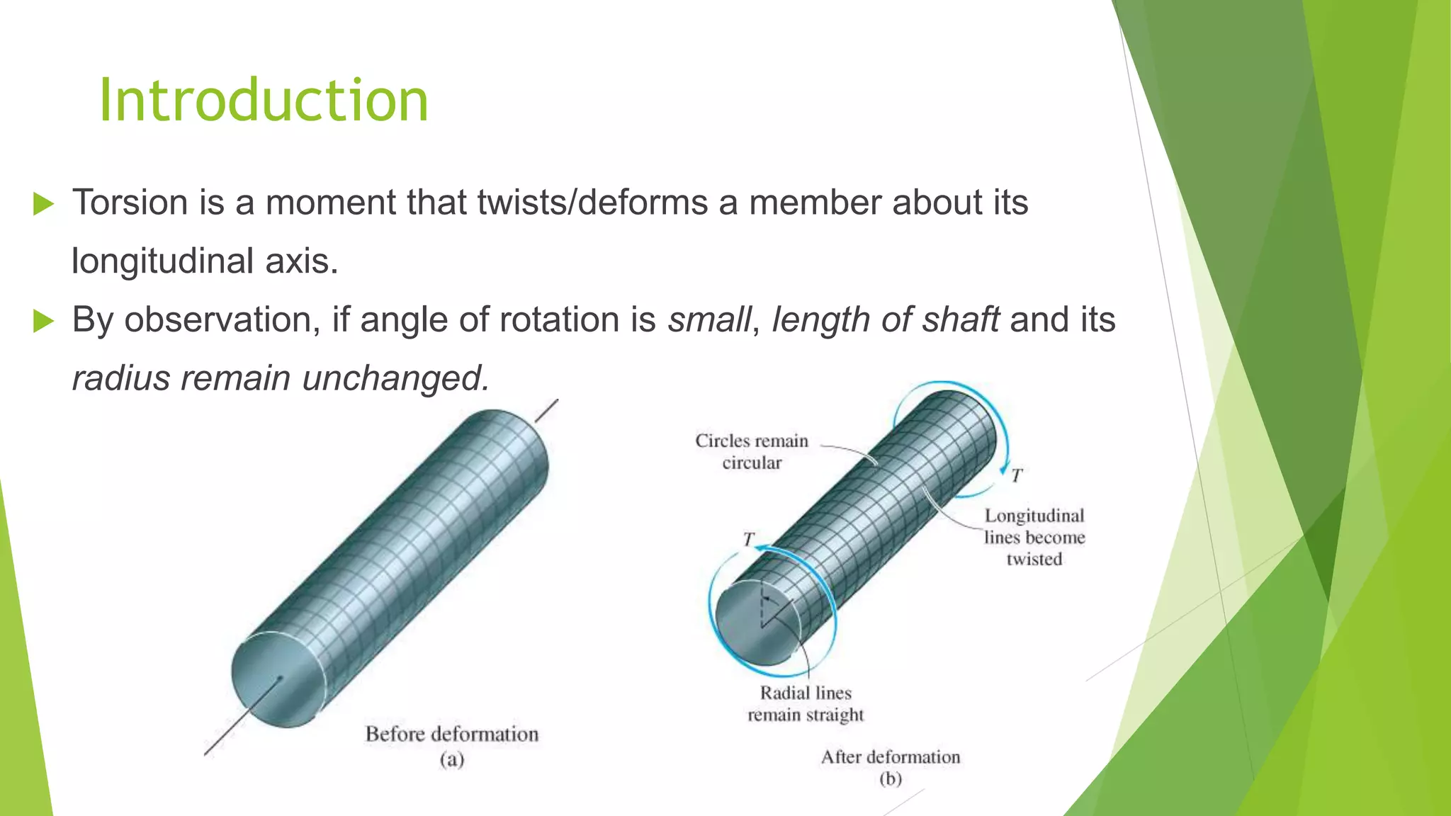
Overview of Torsion, its definition, and fundamental concepts in structural engineering.
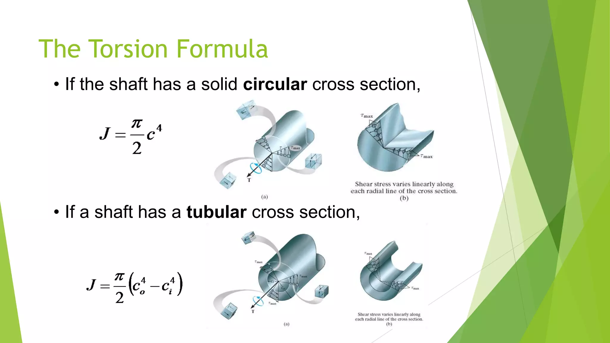
Presentation of Torsion Formula, assumptions for materials and stress analyses for shafts.
Discussion on power transmission through shafts including formulas for torque and shaft design.
Real-world example calculating shaft diameter under specific power and stress conditions.
Definition and explanation of torsional rigidity and its significance in shaft design.
Thank you note concluding the presentation.


![MTORSION [EngineeringDuniya.co MTORSION [EngineeringDuniya.com].pptm].ppt](https://cdn.slidesharecdn.com/ss_thumbnails/mtorsionengineeringduniya-241112074730-b7e902c3-thumbnail.jpg?width=640&height=640&fit=bounds)


