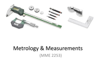
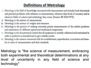
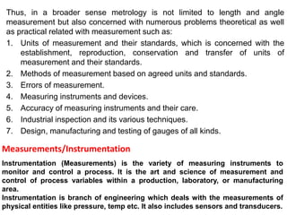
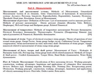
This document discusses metrology and measurements. Metrology is defined as the science of measurement, encompassing both experimental and theoretical determinations at any level of uncertainty across science and technology. Metrology includes establishing measurement units and standards, methods of measurement based on agreed units and standards, measuring errors, instruments and devices, instrument accuracy, and industrial inspection techniques. Instrumentation refers to the variety of measuring instruments used to monitor and control processes, and is concerned with measuring physical variables like pressure and temperature. The document outlines parts on measurements and metrology, and discusses reference books on the topics.

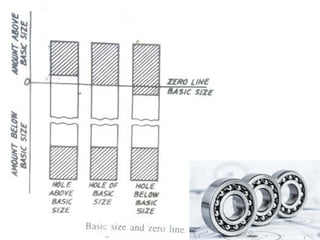


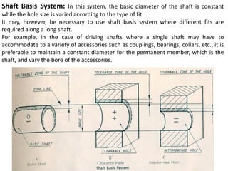
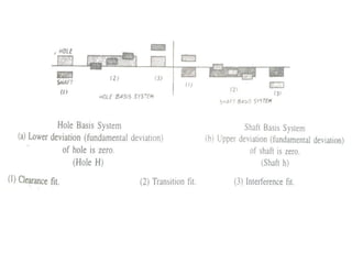
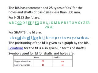
![Hole Basis: In this system, the basic diameter of the hole is constant while the shaft
size is varied according to the type of fit.
Significance of Hole basis system: The bureau of Indian Standards (BIS) recommends
both hole basis and shaft basis systems, but their selection depends on the
production methods. Generally, holes are produced by drilling, boring, reaming,
broaching, etc. whereas shafts are either turned or ground.
If the shaft basis system is used to specify the limit dimensions to obtain various
types of fits, number of holes of different sizes are required, which in turn requires
tools of different sizes.[ Since drill bits comes in standard sizes only]](https://image.slidesharecdn.com/limitsfitsandtolerancesppt-240314065048-3ee98024/85/Limits-Fits-and-Tolerances-ppt-pdf-32-320.jpg)


![Ppt Fits Tolerances[1]](https://cdn.slidesharecdn.com/ss_thumbnails/pptfitstolerances1-091107045206-phpapp01-thumbnail.jpg?width=640&height=640&fit=bounds)


