
Recommended
More Related Content
Similar to RECIPROCATING_AIR_COMPRESSOR.ppt .
Similar to RECIPROCATING_AIR_COMPRESSOR.ppt . (20)
More from happycocoman
More from happycocoman (20)
Recently uploaded
Recently uploaded (20)
RECIPROCATING_AIR_COMPRESSOR.ppt .
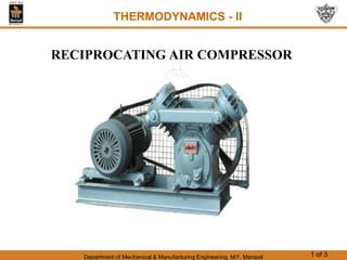
- 1. Department of Mechanical & Manufacturing Engineering, MIT, Manipal 1 of 3 THERMODYNAMICS - II RECIPROCATING AIR COMPRESSOR
- 2. Department of Mechanical & Manufacturing Engineering, MIT, Manipal 2 of 3 Reciprocating compressor The function of a compressor is to take a definite quantity of fluid and deliver it at a required pressure. The most efficient machine is one which will accomplish this with a minimum input of mechanical work. All compressing devices are power absorbing devices, which require an external power source. The external power source may be electrical motor or IC engines connected directly to the compressor using coupling. Reciprocating compressors are similar to IC engines construction but without any fuel delivery system.
- 3. Department of Mechanical & Manufacturing Engineering, MIT, Manipal 3 of 3 USES OF COMPRESSED AIR: 1) In mines due to danger of fire no electrical or fuel motors are used. The compressed air after cooling passed down to mines for operating air motors, pneumatic drills, pumps, drill sharpeners, coal cutters, air motors, pneumatic drills, pumps, drill sharpeners etc., 2) It is used for inflating tubes in automobiles, spray painting, and air washing of vehicles in service stations. 3) It is used in operating the lifts and hoists. 4) It is used in starting and supercharging of the internal combustion engines.
- 4. Department of Mechanical & Manufacturing Engineering, MIT, Manipal 4 of 3 5. It is used in pneumatic brakes in automobiles, locomotives, railway carriages etc 6. It is used in sand blasting in industries, chemical processing, blast furnaces, chemical processing. 7. It is used in combustion of fuels in gas turbines
- 5. Department of Mechanical & Manufacturing Engineering, MIT, Manipal 5 of 3 THERMODYNAMICS - II CLASSIFICATION: Depending upon energy transfer, compressors are classified as (A) According to type of compression i) Positive displacement machines ii) Dynamic machines (B) Depending upon the pressure ratio i) Fans (pressure ratio <1.1) ii) Blowers (pressure ratio > 1.1 <2.3) iii) Compressors (pressure ratio > 2.3)
- 6. Department of Mechanical & Manufacturing Engineering, MIT, Manipal 6 of 3 (C) According to use of piston sides i) Single acting ii) Double acting (D) According to number of stages i) Single stage ii) Multi stage
- 7. Department of Mechanical & Manufacturing Engineering, MIT, Manipal 7 of 3
- 8. Department of Mechanical & Manufacturing Engineering, MIT, Manipal 8 of 3 THERMODYNAMICS - II SINGLE STAGE RECIPROCATING COMPRESSOR WITHOUT CLEARANCE • Consider a single stage reciprocating air compressor without flow resistance at inlet and delivery and without clearance. • Assuming working fluid is air which is a perfect gas • Let P1=initial pressure before compression. • V1= initial volume • V2=volume after compression • P2=Final pressure
- 9. Department of Mechanical & Manufacturing Engineering, MIT, Manipal 9 of 3 • There are 3 possible processes with n=1, n = γ = and 1<n< γ When n=1, PV=C the compression is called isothermal When n= γ, the compression is called rev. adiabatic When 1<n< γ, the compression is called polytropic • The work done on the air is given by the area of the indicator diagram and work done will be minimum when the area of indicator diagram is minimum. • The height of the indicator diagram is fixed by the required pressure ratio and the length 4-1 by the cylinder volume. • The variable which can influence the area of the diagram is 1-2 which is decided by the index ‘n’ in the equation PVn=C.
- 10. Department of Mechanical & Manufacturing Engineering, MIT, Manipal 10 of 3 (i) Work done in a polytropic process
- 11. Department of Mechanical & Manufacturing Engineering, MIT, Manipal 11 of 3
- 12. Department of Mechanical & Manufacturing Engineering, MIT, Manipal 12 of 3
- 13. Department of Mechanical & Manufacturing Engineering, MIT, Manipal 13 of 3 THERMODYNAMICS - II EXPRESSION FOR WORK OF COMPRESSION – WITH CLEARANCE
- 14. Department of Mechanical & Manufacturing Engineering, MIT, Manipal 14 of 3 VOLUMETRIC EFFICIENCY: • Due to clearance volume intake capacity of air compressor reduces. • The ratio of actual volume sucked to the theoretical volume swept by the piston is known as volumetric efficiency. • It is the tool to gauge the performance of a reciprocating compressor. Free Air Delivered: Free air delivered is the actual volume of air delivered at stated pressure reduced to standard temperature and pressure i.e., 1 bar and 15oC
- 15. Department of Mechanical & Manufacturing Engineering, MIT, Manipal 15 of 3 Volumetric efficiency in terms of %age of clearance and pressure ratio: Consider a single stage reciprocating compressor with clearance as shown in the figure
- 16. Department of Mechanical & Manufacturing Engineering, MIT, Manipal 16 of 3
- 17. Department of Mechanical & Manufacturing Engineering, MIT, Manipal 17 of 3
- 18. Department of Mechanical & Manufacturing Engineering, MIT, Manipal 18 of 3
- 19. Department of Mechanical & Manufacturing Engineering, MIT, Manipal 19 of 3
- 20. Department of Mechanical & Manufacturing Engineering, MIT, Manipal 20 of 3
- 21. Department of Mechanical & Manufacturing Engineering, MIT, Manipal 21 of 3 THERMODYNAMICS - II MULTISTAGING OF RECIPROCATING AIR COMPRESSORS In a single stage air compressor as the pressure ratio increases leakage past the piston increases and compressor requires robust construction. A high compression process, high temperature affects the operation of delivery valve and lubrication problem arises. As the pressure ratio increases work of compression increases. It is for these reasons that if a higher compression is needed the overall pressure ratio can be divided into two or more stages.
- 22. Department of Mechanical & Manufacturing Engineering, MIT, Manipal 22 of 3 ADVANTAGES OF MULTISTAGE COMPRESSION: Multistage compressor requires less power as compared to single stage compressor for the same delivery pressure and same quantity free air due to intercooling. Volumetric efficiency will be higher due to lower temperature and pressure ranges in each stage. Due to phasing of operation into stages, a better mechanical balance is possible with multistage compression. Due to lower temperature range in each stage lubrication will be better in multistage compression. Because of lower pressure range lower pressure cylinder is made thin and high pressure cylinder is made thicker, so that overall saving in material is possible compared t single stage.
- 23. Department of Mechanical & Manufacturing Engineering, MIT, Manipal 23 of 3
- 24. Department of Mechanical & Manufacturing Engineering, MIT, Manipal 24 of 3
- 25. Department of Mechanical & Manufacturing Engineering, MIT, Manipal 25 of 3
- 26. Department of Mechanical & Manufacturing Engineering, MIT, Manipal 26 of 3
- 27. Department of Mechanical & Manufacturing Engineering, MIT, Manipal 27 of 3
- 28. Department of Mechanical & Manufacturing Engineering, MIT, Manipal 28 of 3
- 29. Department of Mechanical & Manufacturing Engineering, MIT, Manipal 29 of 3
- 30. Department of Mechanical & Manufacturing Engineering, MIT, Manipal 30 of 3
- 31. Department of Mechanical & Manufacturing Engineering, MIT, Manipal 31 of 3
- 32. Department of Mechanical & Manufacturing Engineering, MIT, Manipal 32 of 3
- 33. Department of Mechanical & Manufacturing Engineering, MIT, Manipal 33 of 3
- 34. Department of Mechanical & Manufacturing Engineering, MIT, Manipal 34 of 3 Heat Rejected per Kg. & per stage in multi stage compression: 1-2-polytropic compression in the first stage 2-2’-constant pressure cooling process in the intercooler 2’-3- Polytropic compression in the second stage 1-3”-isentropic compression in one step (stage) 1-3’- Polytropic compression in one stage The given figure shows graphical representation of heat rejected during compression and in the intercooler.
- 35. Department of Mechanical & Manufacturing Engineering, MIT, Manipal 35 of 3 If the air is cooled to its initial temperature the whole of the work done in the compressor must be rejected to the cooling medium
- 36. Department of Mechanical & Manufacturing Engineering, MIT, Manipal 36 of 3