SlideShare a Scribd company logo
1 of 91
MANIPAL INSTITUTE OF TECHNOLOGY
Department of Mechanical & Manufacturing Engineering, MIT, Manipal 1
MANIPAL INSTITUTE OF TECHNOLOGY
STRAIN
Measurement
MANIPAL INSTITUTE OF TECHNOLOGY
Department of Mechanical & Manufacturing Engineering, MIT, Manipal 2
MANIPAL INSTITUTE OF TECHNOLOGY
Department of Mechanical & Manufacturing Engineering, MIT, Manipal 3
MANIPAL INSTITUTE OF TECHNOLOGY
 Electrical resistance strain gauges are very widely used for strain
measurement.
 Its operation is based on the principle that the electrical
resistance of a conductor changes when it is
subjected to a mechanical deformation.
 Typically an electric conductor is bonded to the specimen with
an insulating cement under no-load conditions.
 A load is then applied, which produces a deformation in both
the specimen and the resistance element.
MANIPAL INSTITUTE OF TECHNOLOGY
Department of Mechanical & Manufacturing Engineering, MIT, Manipal 4
MANIPAL INSTITUTE OF TECHNOLOGY
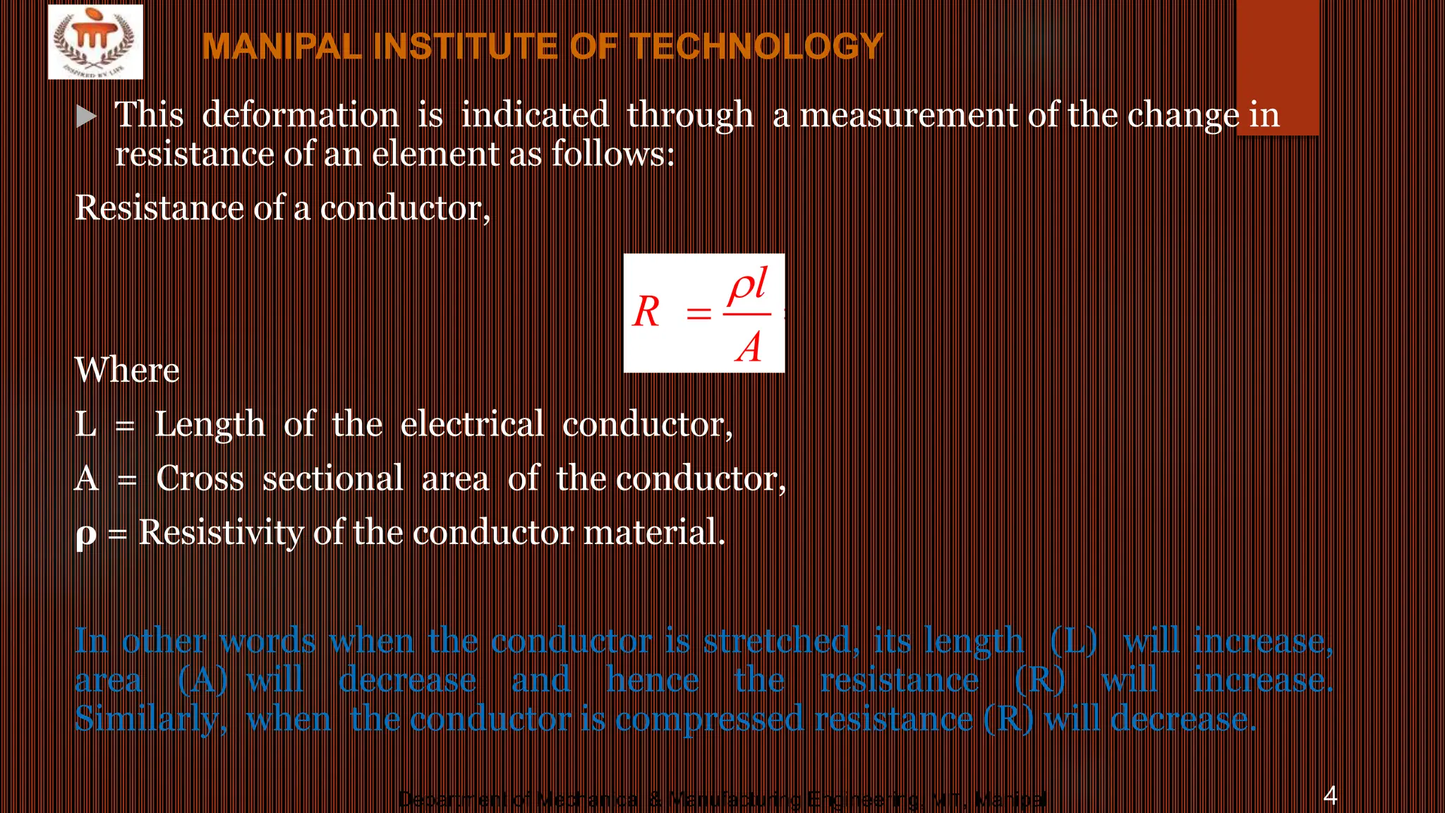
 This deformation is indicated through a measurement of the change in
resistance of an element as follows:
Resistance of a conductor,
Where
L = Length of the electrical conductor,
A = Cross sectional area of the conductor,
ρ = Resistivity of the conductor material.
In other words when the conductor is stretched, its length (L) will increase,
area (A) will decrease and hence the resistance (R) will increase.
Similarly, when the conductor is compressed resistance (R) will decrease.
2
..................(1)
l l
C
R
A D
 
 
MANIPAL INSTITUTE OF TECHNOLOGY
Department of Mechanical & Manufacturing Engineering, MIT, Manipal 5
MANIPAL INSTITUTE OF TECHNOLOGY
Bonded Resistance-strain Gauge
 The bonded gauge is a suitably shaped piece of resistance metal which is
bonded close to the surface whose strain is to be measured.
 The exploded view Fig. shows a thin wire shaped into a grid pattern, which
is cemented between thin sheets of insulating material such as paper or
plastic.
 The grid can also be made from thin metal foil. The assembled gauge is
bonded to the surface with a thin layer of adhesive and finally
waterproofed with a layer of wax or lacquer.
 The grid experiences the same strain as the material to which it is bonded.
MANIPAL INSTITUTE OF TECHNOLOGY
Department of Mechanical & Manufacturing Engineering, MIT, Manipal 6
MANIPAL INSTITUTE OF TECHNOLOGY
 The gauge is most sensitive to the strain along its axial direction X-X while the
strain in the Y-Y direction occurs due to Poisson's ratio effect.
 This causes change of resistance, and may lead to an error of 2% in the
measured strain when using the wire bonded gauge.
 However, in the foil gauge the thickened ends reduce this cross-sensitivity effect
to virtually zero.
 If the direction of principal strain is not known then cluster of three or more
strain gauges are used, which are called rosettes.
MANIPAL INSTITUTE OF TECHNOLOGY
Department of Mechanical & Manufacturing Engineering, MIT, Manipal 7
MANIPAL INSTITUTE OF TECHNOLOGY
Department of Mechanical & Manufacturing Engineering, MIT, Manipal 8
MANIPAL INSTITUTE OF TECHNOLOGY
Department of Mechanical & Manufacturing Engineering, MIT, Manipal 9
MANIPAL INSTITUTE OF TECHNOLOGY
Department of Mechanical & Manufacturing Engineering, MIT, Manipal 10
MANIPAL INSTITUTE OF TECHNOLOGY
a) Single element
b) Two-element rosette
c) Three – element rosette
d) Special – purpose gauges (used
on pressurized diaphragms)
MANIPAL INSTITUTE OF TECHNOLOGY
Department of Mechanical & Manufacturing Engineering, MIT, Manipal 11
MANIPAL INSTITUTE OF TECHNOLOGY
Department of Mechanical & Manufacturing Engineering, MIT, Manipal 12
MANIPAL INSTITUTE OF TECHNOLOGY
Department of Mechanical & Manufacturing Engineering, MIT, Manipal 13
MANIPAL INSTITUTE OF TECHNOLOGY
Department of Mechanical & Manufacturing Engineering, MIT, Manipal 14
MANIPAL INSTITUTE OF TECHNOLOGY
Department of Mechanical & Manufacturing Engineering, MIT, Manipal 15
MANIPAL INSTITUTE OF TECHNOLOGY
15
MANIPAL INSTITUTE OF TECHNOLOGY
Department of Mechanical & Manufacturing Engineering, MIT, Manipal 16
MANIPAL INSTITUTE OF TECHNOLOGY
16
MANIPAL INSTITUTE OF TECHNOLOGY
Department of Mechanical & Manufacturing Engineering, MIT, Manipal 17
MANIPAL INSTITUTE OF TECHNOLOGY
Department of Mechanical & Manufacturing Engineering, MIT, Manipal 18
MANIPAL INSTITUTE OF TECHNOLOGY
Department of Mechanical & Manufacturing Engineering, MIT, Manipal 19
MANIPAL INSTITUTE OF TECHNOLOGY
Department of Mechanical & Manufacturing Engineering, MIT, Manipal 20
MANIPAL INSTITUTE OF TECHNOLOGY
Department of Mechanical & Manufacturing Engineering, MIT, Manipal 21
MANIPAL INSTITUTE OF TECHNOLOGY
Department of Mechanical & Manufacturing Engineering, MIT, Manipal 22
MANIPAL INSTITUTE OF TECHNOLOGY
Department of Mechanical & Manufacturing Engineering, MIT, Manipal 23
MANIPAL INSTITUTE OF TECHNOLOGY
Department of Mechanical & Manufacturing Engineering, MIT, Manipal 24
MANIPAL INSTITUTE OF TECHNOLOGY
 Wire type:
It consists of a very fine wire of diameter 0.025 mm
wounded into a grid shape as shown in figure and the
grid is cemented between two pieces of thin paper with
plastic or ceramic backing.
This is done in order that the grid of the wire may be
easily handled. This is securely bonded with a suitable
cement to the surface of the member in which the strain has
to be measured.
MANIPAL INSTITUTE OF TECHNOLOGY
Department of Mechanical & Manufacturing Engineering, MIT, Manipal 25
MANIPAL INSTITUTE OF TECHNOLOGY
Foil type resistance strain gauge:
These gauges usually employs a foil less than 0.005 mm
thick.
The common form of foil type gauge consists of a metal foil
grid element on a thin epoxy support.
Epoxy filled with fiber glass is used for high
temperatures.
These foil type gauges are manufactured by printing on a
thin sheet of metal alloy with an acid-resistant ink, and
then the unprinted portion is etched away.
Foil gauges have the advantages of improved hysteresis,
better fatigue life and lateral strain sensitivity.
MANIPAL INSTITUTE OF TECHNOLOGY
Department of Mechanical & Manufacturing Engineering, MIT, Manipal 26
MANIPAL INSTITUTE OF TECHNOLOGY
It is thinner and more flexible, thus permitting it to be applied to
fillets and sharply curved surfaces.
The common wire or foil gauges are called metallic gauges.
MANIPAL INSTITUTE OF TECHNOLOGY
Department of Mechanical & Manufacturing Engineering, MIT, Manipal 27
MANIPAL INSTITUTE OF TECHNOLOGY
Semiconductor or Piezoresistive strain gauge:
Semiconductor gauges are cut from single crystals of silicon
or germanium in which are combined exact amounts of
impurities such as boron which impart certain desirable
characteristics.
The same types of backing, bonding materials, and
mounting techniques as those used for metallic gauges
can be used for semiconductor gauges.
When the gauge is bonded to a member which is strained,
causes changes of current in the semi-conductor
material.
The advantages of semiconductor gauges is their high
strain sensitivity which allows very small strains to be
measured accurately.
MANIPAL INSTITUTE OF TECHNOLOGY
Department of Mechanical & Manufacturing Engineering, MIT, Manipal 28
MANIPAL INSTITUTE OF TECHNOLOGY
 A gauge whose electrical resistance increases in response
to tensile strain is known as positive or p-type
semiconductor gauge.
 On the other hand when the resistance decreases in response
to tensile strain then it is known as negative or n-type
semiconductor gauge.
The semiconductor gauge consists of a rectangular filament of about 0.05 mm thick
by 0.25 mm wide and gauge length varies from 1.5 to 12 mm as shown in Figure.
MANIPAL INSTITUTE OF TECHNOLOGY
Department of Mechanical & Manufacturing Engineering, MIT, Manipal 29
MANIPAL INSTITUTE OF TECHNOLOGY
Strain Gauge Metals:
 The most common metals used for the manufacture of
metallic strain gauges are:
 alloys of copper and nickel or, alloy of nickel, chromium
and iron with other elements in small percentages.
 Gauges with resistances varying from 60 Ω to 5000
Ω are available.
 The current carried by the gauges for long periods is
around 25 mA to 50 mA.
MANIPAL INSTITUTE OF TECHNOLOGY
Department of Mechanical & Manufacturing Engineering, MIT, Manipal 30
MANIPAL INSTITUTE OF TECHNOLOGY
 Strain Gauge Backing Materials:
The strain-gauges are normally supported on some form of
backing material.
This provides not only the necessary electrical insulation
between the grid and the tested material, but also a
convenient carriage for handling the un-mounted gauge.
Certain types of gauges intended for high temperature
applications use a temporary backing which will be
removed when the grid is mounted.
In this case, at the time of installation the grid is
embedded in a special ceramic material that provides
the necessary electrical insulation and high-temperature
adhesion.
MANIPAL INSTITUTE OF TECHNOLOGY
Department of Mechanical & Manufacturing Engineering, MIT, Manipal 31
MANIPAL INSTITUTE OF TECHNOLOGY
The desirable characteristics for backing materials
are as follows:
1. Minimum thickness consistent with other factors
2. High mechanical and dielectric strength
3. Minimum temperature restrictions
4. Good adherence to cements used, and should be non-
hygroscopic in nature.
Common backing materials include thin paper, phenolic-
impregnated paper, epoxy type plastic films, and epoxy-
impregnated fiber glass.
MANIPAL INSTITUTE OF TECHNOLOGY
Department of Mechanical & Manufacturing Engineering, MIT, Manipal 32
MANIPAL INSTITUTE OF TECHNOLOGY
 Bonding Materials and Methods:
Strain gauges are attached to the test item by some form of cement
or adhesive.
The adhesives commonly used are cellulose, phenolic, epoxy,
cyanoacrylate, or ceramic etc.
The desirable characteristics of strain-gauge adhesives are as
follows:
1. High mechanical and dielectric strength
2. High creep resistance
3. Minimum temperature restrictions and moisture absorption
4. Good adherence with ease of application
5. The capacity to set fast
MANIPAL INSTITUTE OF TECHNOLOGY
Department of Mechanical & Manufacturing Engineering, MIT, Manipal 33
MANIPAL INSTITUTE OF TECHNOLOGY
Treatment Regarding Preparation and Mounting of Strain
Gauges:
The following steps should be strictly followed for
proper mounting of the strain gauges:
1. The surface on which the strain gauge has to be
mounted must be properly cleaned by an emery cloth and
bare base material must be exposed.
2. Various traces of grease or oil etc must be removed by
using solvent like acetone.
3. The surface of the strain gauge coming in contact with
the test item should also be free from grease etc.
MANIPAL INSTITUTE OF TECHNOLOGY
Department of Mechanical & Manufacturing Engineering, MIT, Manipal 34
MANIPAL INSTITUTE OF TECHNOLOGY
4. Sufficient quantity of cement is applied to the cleaned
surface and the cleaned gauge is then simply placed on it. Care
should be taken to see that there should not be any air bubble in
between the gauge and the surface. The pressure applied
should not be heavy so that the cement may puncture the paper
and short the grid
5. The gauges are then allowed to set for at least eight or ten hours
before using it. If possible a slight weight may be placed by keeping
a sponge or rubber on the gauge.
6. After the cement is fully cured, the electrical, continuity of grid
must be checked by ohm meter and the electrical leads may be
welded.
MANIPAL INSTITUTE OF TECHNOLOGY
Department of Mechanical & Manufacturing Engineering, MIT, Manipal 35
MANIPAL INSTITUTE OF TECHNOLOGY
Theory of strain gauges
MANIPAL INSTITUTE OF TECHNOLOGY
Department of Mechanical & Manufacturing Engineering, MIT, Manipal 36
MANIPAL INSTITUTE OF TECHNOLOGY
Department of Mechanical & Manufacturing Engineering, MIT, Manipal 37
MANIPAL INSTITUTE OF TECHNOLOGY
Department of Mechanical & Manufacturing Engineering, MIT, Manipal 38
MANIPAL INSTITUTE OF TECHNOLOGY
Department of Mechanical & Manufacturing Engineering, MIT, Manipal 39
MANIPAL INSTITUTE OF TECHNOLOGY
Department of Mechanical & Manufacturing Engineering, MIT, Manipal 40
MANIPAL INSTITUTE OF TECHNOLOGY
Department of Mechanical & Manufacturing Engineering, MIT, Manipal 41
MANIPAL INSTITUTE OF TECHNOLOGY
Department of Mechanical & Manufacturing Engineering, MIT, Manipal 46
MANIPAL INSTITUTE OF TECHNOLOGY
Department of Mechanical & Manufacturing Engineering, MIT, Manipal 47
MANIPAL INSTITUTE OF TECHNOLOGY
Resistance Strain Gauge Bridge
Unbalanced Strain Gauge Bridge
MANIPAL INSTITUTE OF TECHNOLOGY
Department of Mechanical & Manufacturing Engineering, MIT, Manipal 48
MANIPAL INSTITUTE OF TECHNOLOGY
Department of Mechanical & Manufacturing Engineering, MIT, Manipal 49
MANIPAL INSTITUTE OF TECHNOLOGY
Department of Mechanical & Manufacturing Engineering, MIT, Manipal 50
MANIPAL INSTITUTE OF TECHNOLOGY
Department of Mechanical & Manufacturing Engineering, MIT, Manipal 51
MANIPAL INSTITUTE OF TECHNOLOGY
51
2. Voltage Sensitive bridge:
MANIPAL INSTITUTE OF TECHNOLOGY
Department of Mechanical & Manufacturing Engineering, MIT, Manipal 52
MANIPAL INSTITUTE OF TECHNOLOGY
𝑖1=𝑖3 & 𝑖2=𝑖4
Assume that input impedance of the meter is infinite and therefore 𝑖𝑚=0
Output voltage 𝑒0 = 𝑣𝑜𝑙𝑡𝑎𝑔𝑒 𝑎𝑐𝑟𝑜𝑠𝑠 𝑡ℎ𝑒 𝑡𝑒𝑟𝑚𝑖𝑛𝑎𝑙𝑠 𝑏 𝑎𝑛𝑑 𝑑 = 𝑖1𝑅1 − 𝑖2𝑅2
𝑖1=
𝑒𝑖
𝑅1 + 𝑅3
𝑖2=
𝑒𝑖
𝑅2 + 𝑅4
𝑒0 =
𝑅1
𝑅1 + 𝑅3
−
𝑅2
𝑅2 + 𝑅4
𝑒𝑖
𝑅1𝑅2 + 𝑅1𝑅4 − 𝑅1𝑅2 − 𝑅3𝑅2
(𝑅1 + 𝑅3)(𝑅2 + 𝑅4)
𝑒𝑖
=
Suppose 𝑅1 changes by an amount Δ𝑅1. This causes a change in output voltage Δ𝑒0
(𝑅1+Δ𝑅1)𝑅4 − 𝑅3𝑅2
(𝑅1 + Δ𝑅1 + 𝑅3)(𝑅2 + 𝑅4)
𝑒𝑖
𝑒0 + Δ𝑒0 =
Deviding by 𝑅1𝑅4
MANIPAL INSTITUTE OF TECHNOLOGY
Department of Mechanical & Manufacturing Engineering, MIT, Manipal 53
MANIPAL INSTITUTE OF TECHNOLOGY
𝑒0 + Δ𝑒0 =
(1 +
Δ𝑅1
𝑅1
)𝑅4 −
𝑅3𝑅2
𝑅1𝑅4
(1 +
Δ𝑅1
𝑅1
+
𝑅3
𝑅1
)(1 +
𝑅2
𝑅4
)
𝑒𝑖
To simplify the relationship assume 𝑅1 = 𝑅2 = 𝑅3 = 𝑅4 = 𝑅
Under these conditions 𝑒0=0
Δ𝑅
𝑅
(4 + 2
Δ𝑅
𝑅
)
𝑒𝑖
Δ𝑒0 =
Resistance change is very small compared to initial resistance
4 >> 2
Δ𝑅
𝑅
Δ𝑒0 =
Δ𝑅
𝑅
4
𝑒𝑖 Hence Bridge sensitivity =𝑆𝐵 =
Δ𝑒0
Δ𝑅
=
𝑒𝑖
4𝑅
MANIPAL INSTITUTE OF TECHNOLOGY
Department of Mechanical & Manufacturing Engineering, MIT, Manipal 54
MANIPAL INSTITUTE OF TECHNOLOGY
𝑅1 = 𝑅2 = 𝑅3 = 𝑅4 = 𝑅𝑔 the strain gauge resistance and changes to ∆𝑅𝑔
Δ𝑒0 =
∆𝑅𝑔
𝑅𝑔
(4 + 2
∆𝑅𝑔
𝑅𝑔
)
𝑒𝑖
4 >> 2
∆𝑅𝑔
𝑅𝑔
Δ𝑒0 =
∆𝑅𝑔
𝑅𝑔
4
𝑒𝑖
𝐺𝑓.𝜀
4
𝑒𝑖
Δ𝑒0 =
MANIPAL INSTITUTE OF TECHNOLOGY
Department of Mechanical & Manufacturing Engineering, MIT, Manipal 55
MANIPAL INSTITUTE OF TECHNOLOGY
 Signal enhancement factor of the Wheatstone bridge is
defined as the maximum output due to changes in various
strain gauges of the bridge to the maximum output obtainable
with the use of only one strain gauge on the member.
 In other words, more than one active gauge (subjected to
strain), suitably arranged, can leads to increased sensitivity
or signal enhancement.
Strain gauge arrangement
MANIPAL INSTITUTE OF TECHNOLOGY
Department of Mechanical & Manufacturing Engineering, MIT, Manipal 56
MANIPAL INSTITUTE OF TECHNOLOGY
Strain gauge arrangement
 The following two factors are kept in mind while deciding the
arrangements of strain gauges on elastic members, for
measuring various physical variables:
 High sensitivity and Temperature compensation
MANIPAL INSTITUTE OF TECHNOLOGY
Department of Mechanical & Manufacturing Engineering, MIT, Manipal 57
MANIPAL INSTITUTE OF TECHNOLOGY
All the possible arrangement
of four strain gauges on
elastic members, for measuring
axial force with signal
enhancement factor.
Signal enhancement factor = 2(1 + ν)
MANIPAL INSTITUTE OF TECHNOLOGY
Department of Mechanical & Manufacturing Engineering, MIT, Manipal 58
MANIPAL INSTITUTE OF TECHNOLOGY
 All the possible arrangement of four strain gauges on
elastic members, for measuring bending force with
signal enhancement factor.
Signal enhancement factor = 2(1 + ν)
MANIPAL INSTITUTE OF TECHNOLOGY
Department of Mechanical & Manufacturing Engineering, MIT, Manipal 59
MANIPAL INSTITUTE OF TECHNOLOGY
Department of Mechanical & Manufacturing Engineering, MIT, Manipal 60
MANIPAL INSTITUTE OF TECHNOLOGY
Department of Mechanical & Manufacturing Engineering, MIT, Manipal 61
MANIPAL INSTITUTE OF TECHNOLOGY
Department of Mechanical & Manufacturing Engineering, MIT, Manipal 62
MANIPAL INSTITUTE OF TECHNOLOGY
Department of Mechanical & Manufacturing Engineering, MIT, Manipal 63
MANIPAL INSTITUTE OF TECHNOLOGY
Department of Mechanical & Manufacturing Engineering, MIT, Manipal 64
MANIPAL INSTITUTE OF TECHNOLOGY
Department of Mechanical & Manufacturing Engineering, MIT, Manipal 65
MANIPAL INSTITUTE OF TECHNOLOGY
Department of Mechanical & Manufacturing Engineering, MIT, Manipal 66
MANIPAL INSTITUTE OF TECHNOLOGY
Department of Mechanical & Manufacturing Engineering, MIT, Manipal 67
MANIPAL INSTITUTE OF TECHNOLOGY
Department of Mechanical & Manufacturing Engineering, MIT, Manipal 68
MANIPAL INSTITUTE OF TECHNOLOGY
Department of Mechanical & Manufacturing Engineering, MIT, Manipal 71
MANIPAL INSTITUTE OF TECHNOLOGY
Department of Mechanical & Manufacturing Engineering, MIT, Manipal 72
MANIPAL INSTITUTE OF TECHNOLOGY
Department of Mechanical & Manufacturing Engineering, MIT, Manipal 73
MANIPAL INSTITUTE OF TECHNOLOGY
Department of Mechanical & Manufacturing Engineering, MIT, Manipal 74
MANIPAL INSTITUTE OF TECHNOLOGY
Department of Mechanical & Manufacturing Engineering, MIT, Manipal 75
MANIPAL INSTITUTE OF TECHNOLOGY
Temperature Compensation
 One of the most important and critical factors in the use of
resistance strain gauges is temperature sensitivity. Although
compensation is provided in the electrical circuitry, for a majority
of the applications, the problem is not eliminated completely.
 The following three factors are involved:
1. The gauge is unable to differentiate the strain resulting from the
differential expansion existing between the grid support and the
proper grid from the load strain.
2. The resistivity changes with the change in temperature.
3. The strong magnetic field has an influence on the gauge
performance.
MANIPAL INSTITUTE OF TECHNOLOGY
Department of Mechanical & Manufacturing Engineering, MIT, Manipal 76
MANIPAL INSTITUTE OF TECHNOLOGY
The Adjacent-Arm Compensating Gauge
The active strain gauge is installed on the
test specimen while the dummy gauge is
installed on a like piece of material and is
not subjected to any strain. The bridge is
initially balanced and therefore
If the gauges in arms 1 and 2 are alike and
mounted on similar materials and if both
gauges experience the same resistance
shift, Rt caused by temperature change,
then
MANIPAL INSTITUTE OF TECHNOLOGY
Department of Mechanical & Manufacturing Engineering, MIT, Manipal 77
MANIPAL INSTITUTE OF TECHNOLOGY
We see that the bridge remains in balance and the output is
unaffected by the change in temperature. When the
compensating gauge is used merely to complete the bridge and to
balance out the temperature component, it is often referred to as
the "dummy" gauge.
MANIPAL INSTITUTE OF TECHNOLOGY
Department of Mechanical & Manufacturing Engineering, MIT, Manipal 78
MANIPAL INSTITUTE OF TECHNOLOGY
Temperature compensation using more than one
active strain gauge
MANIPAL INSTITUTE OF TECHNOLOGY
Department of Mechanical & Manufacturing Engineering, MIT, Manipal 79
MANIPAL INSTITUTE OF TECHNOLOGY
Department of Mechanical & Manufacturing Engineering, MIT, Manipal 80
MANIPAL INSTITUTE OF TECHNOLOGY
Calibration of strain gauges
Normally, calibration of a measuring system means introducing an accurately
known sample of the variable that is to be measured and then observing the
system`s response.
Once a bonded strain gauge is mounted on the structure under study, it cannot be
removed or transferred.
Moreover the value of the gauge factor specified by the manufacturer of the
gauge has to be taken for granted. With these constraints, the relationship
between the strain and the output of the Wheatstone bridge has to be established.
When the gauge factor and gauge resistance are known, the shunting
method is used to calibrate strain gauge.
MANIPAL INSTITUTE OF TECHNOLOGY
Department of Mechanical & Manufacturing Engineering, MIT, Manipal 81
MANIPAL INSTITUTE OF TECHNOLOGY
In the shunting method, a small known resistance change is introduced at
the strain gauge and then an equivalent strain is calculated. This small
known resistance change is introduced at the strain gauge by shunting a
high resistance across the strain gauge as shown in diagram.
MANIPAL INSTITUTE OF TECHNOLOGY
Department of Mechanical & Manufacturing Engineering, MIT, Manipal 82
MANIPAL INSTITUTE OF TECHNOLOGY
Department of Mechanical & Manufacturing Engineering, MIT, Manipal 83
MANIPAL INSTITUTE OF TECHNOLOGY
Department of Mechanical & Manufacturing Engineering, MIT, Manipal 84
MANIPAL INSTITUTE OF TECHNOLOGY
Strain measurement on rotating shaft
The mounting of four resistance strain gauges on rotating shaft for
measuring the torque transmitted by a shaft with Wheatstone bridge
arrangement.
MANIPAL INSTITUTE OF TECHNOLOGY
Department of Mechanical & Manufacturing Engineering, MIT, Manipal 85
MANIPAL INSTITUTE OF TECHNOLOGY
Department of Mechanical & Manufacturing Engineering, MIT, Manipal 86
MANIPAL INSTITUTE OF TECHNOLOGY
During torsion of cylinder, the principal strains (tensile or compressive) exist
at 45º to the axis.
These can be measured by bonded resistance gauges, as shown in the
figure.
The output is increased by using four strain gauges so that adjacent arms of the
Wheatstone bridge have strains of opposite nature.
For taking signals in and out of the rotating shaft, slip rings and brushes are
used as shown in the figure.
MANIPAL INSTITUTE OF TECHNOLOGY
Department of Mechanical & Manufacturing Engineering, MIT, Manipal 87
MANIPAL INSTITUTE OF TECHNOLOGY
In a solid shaft of diameter d, rotating with rpm N, subjected to torque T,
Power = (2 x π x N x T) / 60
Also, Torque, T= [(fs x π x d3) / 16] ……………………..{ from DDHB }
where fs = Shear stress induced in the shaft.
Shear strain = Shear stress induced in the shaft / Shear modulus
Longitudinal strain in the shaft at 45º to the axis of the shaft, ε45 = Shear strain / 2
MANIPAL INSTITUTE OF TECHNOLOGY
Department of Mechanical & Manufacturing Engineering, MIT, Manipal 88
MANIPAL INSTITUTE OF TECHNOLOGY
Department of Mechanical & Manufacturing Engineering, MIT, Manipal 89
MANIPAL INSTITUTE OF TECHNOLOGY
Department of Mechanical & Manufacturing Engineering, MIT, Manipal 90
MANIPAL INSTITUTE OF TECHNOLOGY
The voltage output, e, is given as
Signal enhancement factor = 2
X 2
Battery Voltage E = Battery Current (R1+R4)
Sensitivity = Voltage output / Strain
MANIPAL INSTITUTE OF TECHNOLOGY
Department of Mechanical & Manufacturing Engineering, MIT, Manipal 91
MANIPAL INSTITUTE OF TECHNOLOGY
Department of Mechanical & Manufacturing Engineering, MIT, Manipal 92
MANIPAL INSTITUTE OF TECHNOLOGY
Department of Mechanical & Manufacturing Engineering, MIT, Manipal 93
MANIPAL INSTITUTE OF TECHNOLOGY
Department of Mechanical & Manufacturing Engineering, MIT, Manipal 94
MANIPAL INSTITUTE OF TECHNOLOGY
The voltage output, e, is given as
Signal enhancement factor = 2(1 + ν)
X 2(1 + ν)
Poisson’s ratio ν = 0.3
Bridge excitation voltage E = 6V
Gauge Factor GF = 2.2
Area of the Strip A = 10 mm2
MANIPAL INSTITUTE OF TECHNOLOGY
Department of Mechanical & Manufacturing Engineering, MIT, Manipal 95
MANIPAL INSTITUTE OF TECHNOLOGY
= 4.785 mV
Deflection of the trace = 4.785/10 = 0.478 cm
MANIPAL INSTITUTE OF TECHNOLOGY
Department of Mechanical & Manufacturing Engineering, MIT, Manipal 96
MANIPAL INSTITUTE OF TECHNOLOGY
Department of Mechanical & Manufacturing Engineering, MIT, Manipal 97
MANIPAL INSTITUTE OF TECHNOLOGY
The voltage output, e, is given as
Signal enhancement factor = 4)
X 4

More Related Content

Similar to Strain Measurement (NEW).pptx .

IRJET- Experimental Investigation on the Mechanical Properties of a PMC and H...
IRJET- Experimental Investigation on the Mechanical Properties of a PMC and H...IRJET- Experimental Investigation on the Mechanical Properties of a PMC and H...
IRJET- Experimental Investigation on the Mechanical Properties of a PMC and H...IRJET Journal
 
Mechanical workshop practice-II --2015 by sudarshan.bollapu
Mechanical workshop practice-II  --2015 by sudarshan.bollapuMechanical workshop practice-II  --2015 by sudarshan.bollapu
Mechanical workshop practice-II --2015 by sudarshan.bollapuDr B Sudarshan
 
IRJET- Optimization of WEDM Process Parameters on Machining of AA6082/SiC Met...
IRJET- Optimization of WEDM Process Parameters on Machining of AA6082/SiC Met...IRJET- Optimization of WEDM Process Parameters on Machining of AA6082/SiC Met...
IRJET- Optimization of WEDM Process Parameters on Machining of AA6082/SiC Met...IRJET Journal
 
IRJET- Experimental Investigation on Nickel Aluminium Alloy by Electric D...
IRJET-  	  Experimental Investigation on Nickel Aluminium Alloy by Electric D...IRJET-  	  Experimental Investigation on Nickel Aluminium Alloy by Electric D...
IRJET- Experimental Investigation on Nickel Aluminium Alloy by Electric D...IRJET Journal
 
Static test study on linear induction motor iccee
Static test study on linear induction motor icceeStatic test study on linear induction motor iccee
Static test study on linear induction motor icceeChandan Kumar
 
Analysis of Voltage Sag on Power Distribution Networks with Different Transfo...
Analysis of Voltage Sag on Power Distribution Networks with Different Transfo...Analysis of Voltage Sag on Power Distribution Networks with Different Transfo...
Analysis of Voltage Sag on Power Distribution Networks with Different Transfo...paperpublications3
 
Zero Voltage Switching Converters
Zero Voltage Switching ConvertersZero Voltage Switching Converters
Zero Voltage Switching Convertersijiert bestjournal
 
Measurements and measuring devices search
Measurements and measuring devices searchMeasurements and measuring devices search
Measurements and measuring devices searchmohamed alamin yahia
 
Btech ii yr final_syllabus_mechanical_engg_group_2014
Btech ii yr final_syllabus_mechanical_engg_group_2014Btech ii yr final_syllabus_mechanical_engg_group_2014
Btech ii yr final_syllabus_mechanical_engg_group_2014Deelip Kumar
 
Finite Element Analysis of MEMS based Piezoresistive Diamond Thin Film Cantil...
Finite Element Analysis of MEMS based Piezoresistive Diamond Thin Film Cantil...Finite Element Analysis of MEMS based Piezoresistive Diamond Thin Film Cantil...
Finite Element Analysis of MEMS based Piezoresistive Diamond Thin Film Cantil...IRJET Journal
 
IRJET- Remote Monitoring of Critical Parameters of HV Substation
IRJET-  	  Remote Monitoring of Critical Parameters of HV SubstationIRJET-  	  Remote Monitoring of Critical Parameters of HV Substation
IRJET- Remote Monitoring of Critical Parameters of HV SubstationIRJET Journal
 
Mechanical behavior and statistical study of aluminum wires belonging to low...
	Mechanical behavior and statistical study of aluminum wires belonging to low...	Mechanical behavior and statistical study of aluminum wires belonging to low...
Mechanical behavior and statistical study of aluminum wires belonging to low...theijes
 
Mechanical behavior and statistical study of aluminum wires belonging to low ...
Mechanical behavior and statistical study of aluminum wires belonging to low ...Mechanical behavior and statistical study of aluminum wires belonging to low ...
Mechanical behavior and statistical study of aluminum wires belonging to low ...theijes
 
Comparative study of the mechanical behavior of polymer materials: between AB...
Comparative study of the mechanical behavior of polymer materials: between AB...Comparative study of the mechanical behavior of polymer materials: between AB...
Comparative study of the mechanical behavior of polymer materials: between AB...theijes
 
Comparative study of the mechanical behavior of polymer materials: between A...
	Comparative study of the mechanical behavior of polymer materials: between A...	Comparative study of the mechanical behavior of polymer materials: between A...
Comparative study of the mechanical behavior of polymer materials: between A...theijes
 
Experimental stress analysis BE notes by mohammed imran
Experimental stress analysis BE notes by mohammed imranExperimental stress analysis BE notes by mohammed imran
Experimental stress analysis BE notes by mohammed imranMohammed Imran
 
Measurement of Form errors complete slides.pdf
Measurement of Form errors complete slides.pdfMeasurement of Form errors complete slides.pdf
Measurement of Form errors complete slides.pdfhappycocoman
 

Similar to Strain Measurement (NEW).pptx . (20)

IRJET- Experimental Investigation on the Mechanical Properties of a PMC and H...
IRJET- Experimental Investigation on the Mechanical Properties of a PMC and H...IRJET- Experimental Investigation on the Mechanical Properties of a PMC and H...
IRJET- Experimental Investigation on the Mechanical Properties of a PMC and H...
 
Mechanical workshop practice-II --2015 by sudarshan.bollapu
Mechanical workshop practice-II  --2015 by sudarshan.bollapuMechanical workshop practice-II  --2015 by sudarshan.bollapu
Mechanical workshop practice-II --2015 by sudarshan.bollapu
 
IRJET- Optimization of WEDM Process Parameters on Machining of AA6082/SiC Met...
IRJET- Optimization of WEDM Process Parameters on Machining of AA6082/SiC Met...IRJET- Optimization of WEDM Process Parameters on Machining of AA6082/SiC Met...
IRJET- Optimization of WEDM Process Parameters on Machining of AA6082/SiC Met...
 
IRJET- Experimental Investigation on Nickel Aluminium Alloy by Electric D...
IRJET-  	  Experimental Investigation on Nickel Aluminium Alloy by Electric D...IRJET-  	  Experimental Investigation on Nickel Aluminium Alloy by Electric D...
IRJET- Experimental Investigation on Nickel Aluminium Alloy by Electric D...
 
review paper
review paperreview paper
review paper
 
Static test study on linear induction motor iccee
Static test study on linear induction motor icceeStatic test study on linear induction motor iccee
Static test study on linear induction motor iccee
 
Analysis of Voltage Sag on Power Distribution Networks with Different Transfo...
Analysis of Voltage Sag on Power Distribution Networks with Different Transfo...Analysis of Voltage Sag on Power Distribution Networks with Different Transfo...
Analysis of Voltage Sag on Power Distribution Networks with Different Transfo...
 
Zero Voltage Switching Converters
Zero Voltage Switching ConvertersZero Voltage Switching Converters
Zero Voltage Switching Converters
 
Measurements and measuring devices search
Measurements and measuring devices searchMeasurements and measuring devices search
Measurements and measuring devices search
 
N044086772
N044086772N044086772
N044086772
 
Btech ii yr final_syllabus_mechanical_engg_group_2014
Btech ii yr final_syllabus_mechanical_engg_group_2014Btech ii yr final_syllabus_mechanical_engg_group_2014
Btech ii yr final_syllabus_mechanical_engg_group_2014
 
Finite Element Analysis of MEMS based Piezoresistive Diamond Thin Film Cantil...
Finite Element Analysis of MEMS based Piezoresistive Diamond Thin Film Cantil...Finite Element Analysis of MEMS based Piezoresistive Diamond Thin Film Cantil...
Finite Element Analysis of MEMS based Piezoresistive Diamond Thin Film Cantil...
 
IRJET- Remote Monitoring of Critical Parameters of HV Substation
IRJET-  	  Remote Monitoring of Critical Parameters of HV SubstationIRJET-  	  Remote Monitoring of Critical Parameters of HV Substation
IRJET- Remote Monitoring of Critical Parameters of HV Substation
 
Mechanical behavior and statistical study of aluminum wires belonging to low...
	Mechanical behavior and statistical study of aluminum wires belonging to low...	Mechanical behavior and statistical study of aluminum wires belonging to low...
Mechanical behavior and statistical study of aluminum wires belonging to low...
 
Mechanical behavior and statistical study of aluminum wires belonging to low ...
Mechanical behavior and statistical study of aluminum wires belonging to low ...Mechanical behavior and statistical study of aluminum wires belonging to low ...
Mechanical behavior and statistical study of aluminum wires belonging to low ...
 
Comparative study of the mechanical behavior of polymer materials: between AB...
Comparative study of the mechanical behavior of polymer materials: between AB...Comparative study of the mechanical behavior of polymer materials: between AB...
Comparative study of the mechanical behavior of polymer materials: between AB...
 
Comparative study of the mechanical behavior of polymer materials: between A...
	Comparative study of the mechanical behavior of polymer materials: between A...	Comparative study of the mechanical behavior of polymer materials: between A...
Comparative study of the mechanical behavior of polymer materials: between A...
 
Railway inspection
Railway inspectionRailway inspection
Railway inspection
 
Experimental stress analysis BE notes by mohammed imran
Experimental stress analysis BE notes by mohammed imranExperimental stress analysis BE notes by mohammed imran
Experimental stress analysis BE notes by mohammed imran
 
Measurement of Form errors complete slides.pdf
Measurement of Form errors complete slides.pdfMeasurement of Form errors complete slides.pdf
Measurement of Form errors complete slides.pdf
 

More from happycocoman

gas turbine cycles.pptx .
gas turbine cycles.pptx                    .gas turbine cycles.pptx                    .
gas turbine cycles.pptx .happycocoman
 
RECIPROCATING_AIR_COMPRESSOR.ppt .
RECIPROCATING_AIR_COMPRESSOR.ppt         .RECIPROCATING_AIR_COMPRESSOR.ppt         .
RECIPROCATING_AIR_COMPRESSOR.ppt .happycocoman
 
SURFACE TEXTURE 2022.pptx .
SURFACE TEXTURE 2022.pptx                  .SURFACE TEXTURE 2022.pptx                  .
SURFACE TEXTURE 2022.pptx .happycocoman
 
Numericals on Raciprocating air compressor.ppt
Numericals on  Raciprocating air compressor.pptNumericals on  Raciprocating air compressor.ppt
Numericals on Raciprocating air compressor.ppthappycocoman
 
Vapor_power cycles KM.pptx ..
Vapor_power cycles KM.pptx            ..Vapor_power cycles KM.pptx            ..
Vapor_power cycles KM.pptx ..happycocoman
 
Vapor power cycles by Anupama.pptx .
Vapor power cycles by Anupama.pptx     .Vapor power cycles by Anupama.pptx     .
Vapor power cycles by Anupama.pptx .happycocoman
 
Performance and Testing of Internal Combustion Engines.ppt
Performance and Testing of Internal Combustion Engines.pptPerformance and Testing of Internal Combustion Engines.ppt
Performance and Testing of Internal Combustion Engines.ppthappycocoman
 
ICenginesNumericals (1).pptx .
ICenginesNumericals (1).pptx             .ICenginesNumericals (1).pptx             .
ICenginesNumericals (1).pptx .happycocoman
 
Air standard cycles_PPT KM1.pptx .
Air standard cycles_PPT KM1.pptx          .Air standard cycles_PPT KM1.pptx          .
Air standard cycles_PPT KM1.pptx .happycocoman
 
Pressure Measurement ppt.pptx .
Pressure Measurement ppt.pptx               .Pressure Measurement ppt.pptx               .
Pressure Measurement ppt.pptx .happycocoman
 
Measurements & Measurement .Systems.pptx
Measurements & Measurement .Systems.pptxMeasurements & Measurement .Systems.pptx
Measurements & Measurement .Systems.pptxhappycocoman
 
Force and torque measurements.pptx .
Force and torque measurements.pptx      .Force and torque measurements.pptx      .
Force and torque measurements.pptx .happycocoman
 
Chapter 11 - SCREW THREADS sllides.pdf .
Chapter 11 - SCREW THREADS sllides.pdf       .Chapter 11 - SCREW THREADS sllides.pdf       .
Chapter 11 - SCREW THREADS sllides.pdf .happycocoman
 
Measurement of form errors.pptx .
Measurement of form errors.pptx            .Measurement of form errors.pptx            .
Measurement of form errors.pptx .happycocoman
 
9. Surface Texture - PPT.pdf .
9. Surface Texture - PPT.pdf               .9. Surface Texture - PPT.pdf               .
9. Surface Texture - PPT.pdf .happycocoman
 
10. Screw Threads - PPT.pdf .
10. Screw Threads - PPT.pdf                    .10. Screw Threads - PPT.pdf                    .
10. Screw Threads - PPT.pdf .happycocoman
 
Limits Fits and Tolerances ppt.pdf .
Limits Fits and Tolerances ppt.pdf     .Limits Fits and Tolerances ppt.pdf     .
Limits Fits and Tolerances ppt.pdf .happycocoman
 
Pressure Measurement ppt.pptx .
Pressure Measurement ppt.pptx             .Pressure Measurement ppt.pptx             .
Pressure Measurement ppt.pptx .happycocoman
 

More from happycocoman (20)

gas turbine cycles.pptx .
gas turbine cycles.pptx                    .gas turbine cycles.pptx                    .
gas turbine cycles.pptx .
 
RECIPROCATING_AIR_COMPRESSOR.ppt .
RECIPROCATING_AIR_COMPRESSOR.ppt         .RECIPROCATING_AIR_COMPRESSOR.ppt         .
RECIPROCATING_AIR_COMPRESSOR.ppt .
 
SURFACE TEXTURE 2022.pptx .
SURFACE TEXTURE 2022.pptx                  .SURFACE TEXTURE 2022.pptx                  .
SURFACE TEXTURE 2022.pptx .
 
Numericals on Raciprocating air compressor.ppt
Numericals on  Raciprocating air compressor.pptNumericals on  Raciprocating air compressor.ppt
Numericals on Raciprocating air compressor.ppt
 
Vapor_power cycles KM.pptx ..
Vapor_power cycles KM.pptx            ..Vapor_power cycles KM.pptx            ..
Vapor_power cycles KM.pptx ..
 
Vapor power cycles by Anupama.pptx .
Vapor power cycles by Anupama.pptx     .Vapor power cycles by Anupama.pptx     .
Vapor power cycles by Anupama.pptx .
 
Performance and Testing of Internal Combustion Engines.ppt
Performance and Testing of Internal Combustion Engines.pptPerformance and Testing of Internal Combustion Engines.ppt
Performance and Testing of Internal Combustion Engines.ppt
 
ICenginesNumericals (1).pptx .
ICenginesNumericals (1).pptx             .ICenginesNumericals (1).pptx             .
ICenginesNumericals (1).pptx .
 
Air standard cycles_PPT KM1.pptx .
Air standard cycles_PPT KM1.pptx          .Air standard cycles_PPT KM1.pptx          .
Air standard cycles_PPT KM1.pptx .
 
Pressure Measurement ppt.pptx .
Pressure Measurement ppt.pptx               .Pressure Measurement ppt.pptx               .
Pressure Measurement ppt.pptx .
 
Measurements & Measurement .Systems.pptx
Measurements & Measurement .Systems.pptxMeasurements & Measurement .Systems.pptx
Measurements & Measurement .Systems.pptx
 
Force and torque measurements.pptx .
Force and torque measurements.pptx      .Force and torque measurements.pptx      .
Force and torque measurements.pptx .
 
FLOW(NEW).pptx .
FLOW(NEW).pptx                          .FLOW(NEW).pptx                          .
FLOW(NEW).pptx .
 
Chapter 11 - SCREW THREADS sllides.pdf .
Chapter 11 - SCREW THREADS sllides.pdf       .Chapter 11 - SCREW THREADS sllides.pdf       .
Chapter 11 - SCREW THREADS sllides.pdf .
 
Measurement of form errors.pptx .
Measurement of form errors.pptx            .Measurement of form errors.pptx            .
Measurement of form errors.pptx .
 
9. Surface Texture - PPT.pdf .
9. Surface Texture - PPT.pdf               .9. Surface Texture - PPT.pdf               .
9. Surface Texture - PPT.pdf .
 
10. Screw Threads - PPT.pdf .
10. Screw Threads - PPT.pdf                    .10. Screw Threads - PPT.pdf                    .
10. Screw Threads - PPT.pdf .
 
Limits Fits and Tolerances ppt.pdf .
Limits Fits and Tolerances ppt.pdf     .Limits Fits and Tolerances ppt.pdf     .
Limits Fits and Tolerances ppt.pdf .
 
Pressure Measurement ppt.pptx .
Pressure Measurement ppt.pptx             .Pressure Measurement ppt.pptx             .
Pressure Measurement ppt.pptx .
 
Gauges ppt.pdf .
Gauges ppt.pdf                              .Gauges ppt.pdf                              .
Gauges ppt.pdf .
 

Recently uploaded

Call for Papers - International Journal of Intelligent Systems and Applicatio...
Call for Papers - International Journal of Intelligent Systems and Applicatio...Call for Papers - International Journal of Intelligent Systems and Applicatio...
Call for Papers - International Journal of Intelligent Systems and Applicatio...Christo Ananth
 
BSides Seattle 2024 - Stopping Ethan Hunt From Taking Your Data.pptx
BSides Seattle 2024 - Stopping Ethan Hunt From Taking Your Data.pptxBSides Seattle 2024 - Stopping Ethan Hunt From Taking Your Data.pptx
BSides Seattle 2024 - Stopping Ethan Hunt From Taking Your Data.pptxfenichawla
 
CCS335 _ Neural Networks and Deep Learning Laboratory_Lab Complete Record
CCS335 _ Neural Networks and Deep Learning Laboratory_Lab Complete RecordCCS335 _ Neural Networks and Deep Learning Laboratory_Lab Complete Record
CCS335 _ Neural Networks and Deep Learning Laboratory_Lab Complete RecordAsst.prof M.Gokilavani
 
UNIT-V FMM.HYDRAULIC TURBINE - Construction and working
UNIT-V FMM.HYDRAULIC TURBINE - Construction and workingUNIT-V FMM.HYDRAULIC TURBINE - Construction and working
UNIT-V FMM.HYDRAULIC TURBINE - Construction and workingrknatarajan
 
PVC VS. FIBERGLASS (FRP) GRAVITY SEWER - UNI BELL
PVC VS. FIBERGLASS (FRP) GRAVITY SEWER - UNI BELLPVC VS. FIBERGLASS (FRP) GRAVITY SEWER - UNI BELL
PVC VS. FIBERGLASS (FRP) GRAVITY SEWER - UNI BELLManishPatel169454
 
Generative AI or GenAI technology based PPT
Generative AI or GenAI technology based PPTGenerative AI or GenAI technology based PPT
Generative AI or GenAI technology based PPTbhaskargani46
 
Intze Overhead Water Tank Design by Working Stress - IS Method.pdf
Intze Overhead Water Tank  Design by Working Stress - IS Method.pdfIntze Overhead Water Tank  Design by Working Stress - IS Method.pdf
Intze Overhead Water Tank Design by Working Stress - IS Method.pdfSuman Jyoti
 
Call for Papers - African Journal of Biological Sciences, E-ISSN: 2663-2187, ...
Call for Papers - African Journal of Biological Sciences, E-ISSN: 2663-2187, ...Call for Papers - African Journal of Biological Sciences, E-ISSN: 2663-2187, ...
Call for Papers - African Journal of Biological Sciences, E-ISSN: 2663-2187, ...Christo Ananth
 
Java Programming :Event Handling(Types of Events)
Java Programming :Event Handling(Types of Events)Java Programming :Event Handling(Types of Events)
Java Programming :Event Handling(Types of Events)simmis5
 
Vivazz, Mieres Social Housing Design Spain
Vivazz, Mieres Social Housing Design SpainVivazz, Mieres Social Housing Design Spain
Vivazz, Mieres Social Housing Design Spaintimesproduction05
 
Booking open Available Pune Call Girls Koregaon Park 6297143586 Call Hot Ind...
Booking open Available Pune Call Girls Koregaon Park  6297143586 Call Hot Ind...Booking open Available Pune Call Girls Koregaon Park  6297143586 Call Hot Ind...
Booking open Available Pune Call Girls Koregaon Park 6297143586 Call Hot Ind...Call Girls in Nagpur High Profile
 
Call for Papers - Educational Administration: Theory and Practice, E-ISSN: 21...
Call for Papers - Educational Administration: Theory and Practice, E-ISSN: 21...Call for Papers - Educational Administration: Theory and Practice, E-ISSN: 21...
Call for Papers - Educational Administration: Theory and Practice, E-ISSN: 21...Christo Ananth
 
Call Girls Pimpri Chinchwad Call Me 7737669865 Budget Friendly No Advance Boo...
Call Girls Pimpri Chinchwad Call Me 7737669865 Budget Friendly No Advance Boo...Call Girls Pimpri Chinchwad Call Me 7737669865 Budget Friendly No Advance Boo...
Call Girls Pimpri Chinchwad Call Me 7737669865 Budget Friendly No Advance Boo...roncy bisnoi
 
KubeKraft presentation @CloudNativeHooghly
KubeKraft presentation @CloudNativeHooghlyKubeKraft presentation @CloudNativeHooghly
KubeKraft presentation @CloudNativeHooghlysanyuktamishra911
 
Extrusion Processes and Their Limitations
Extrusion Processes and Their LimitationsExtrusion Processes and Their Limitations
Extrusion Processes and Their Limitations120cr0395
 
Booking open Available Pune Call Girls Pargaon 6297143586 Call Hot Indian Gi...
Booking open Available Pune Call Girls Pargaon  6297143586 Call Hot Indian Gi...Booking open Available Pune Call Girls Pargaon  6297143586 Call Hot Indian Gi...
Booking open Available Pune Call Girls Pargaon 6297143586 Call Hot Indian Gi...Call Girls in Nagpur High Profile
 

Recently uploaded (20)

Call for Papers - International Journal of Intelligent Systems and Applicatio...
Call for Papers - International Journal of Intelligent Systems and Applicatio...Call for Papers - International Journal of Intelligent Systems and Applicatio...
Call for Papers - International Journal of Intelligent Systems and Applicatio...
 
BSides Seattle 2024 - Stopping Ethan Hunt From Taking Your Data.pptx
BSides Seattle 2024 - Stopping Ethan Hunt From Taking Your Data.pptxBSides Seattle 2024 - Stopping Ethan Hunt From Taking Your Data.pptx
BSides Seattle 2024 - Stopping Ethan Hunt From Taking Your Data.pptx
 
(INDIRA) Call Girl Aurangabad Call Now 8617697112 Aurangabad Escorts 24x7
(INDIRA) Call Girl Aurangabad Call Now 8617697112 Aurangabad Escorts 24x7(INDIRA) Call Girl Aurangabad Call Now 8617697112 Aurangabad Escorts 24x7
(INDIRA) Call Girl Aurangabad Call Now 8617697112 Aurangabad Escorts 24x7
 
Call Now ≽ 9953056974 ≼🔝 Call Girls In New Ashok Nagar ≼🔝 Delhi door step de...
Call Now ≽ 9953056974 ≼🔝 Call Girls In New Ashok Nagar  ≼🔝 Delhi door step de...Call Now ≽ 9953056974 ≼🔝 Call Girls In New Ashok Nagar  ≼🔝 Delhi door step de...
Call Now ≽ 9953056974 ≼🔝 Call Girls In New Ashok Nagar ≼🔝 Delhi door step de...
 
CCS335 _ Neural Networks and Deep Learning Laboratory_Lab Complete Record
CCS335 _ Neural Networks and Deep Learning Laboratory_Lab Complete RecordCCS335 _ Neural Networks and Deep Learning Laboratory_Lab Complete Record
CCS335 _ Neural Networks and Deep Learning Laboratory_Lab Complete Record
 
UNIT-V FMM.HYDRAULIC TURBINE - Construction and working
UNIT-V FMM.HYDRAULIC TURBINE - Construction and workingUNIT-V FMM.HYDRAULIC TURBINE - Construction and working
UNIT-V FMM.HYDRAULIC TURBINE - Construction and working
 
PVC VS. FIBERGLASS (FRP) GRAVITY SEWER - UNI BELL
PVC VS. FIBERGLASS (FRP) GRAVITY SEWER - UNI BELLPVC VS. FIBERGLASS (FRP) GRAVITY SEWER - UNI BELL
PVC VS. FIBERGLASS (FRP) GRAVITY SEWER - UNI BELL
 
Generative AI or GenAI technology based PPT
Generative AI or GenAI technology based PPTGenerative AI or GenAI technology based PPT
Generative AI or GenAI technology based PPT
 
(INDIRA) Call Girl Meerut Call Now 8617697112 Meerut Escorts 24x7
(INDIRA) Call Girl Meerut Call Now 8617697112 Meerut Escorts 24x7(INDIRA) Call Girl Meerut Call Now 8617697112 Meerut Escorts 24x7
(INDIRA) Call Girl Meerut Call Now 8617697112 Meerut Escorts 24x7
 
Intze Overhead Water Tank Design by Working Stress - IS Method.pdf
Intze Overhead Water Tank  Design by Working Stress - IS Method.pdfIntze Overhead Water Tank  Design by Working Stress - IS Method.pdf
Intze Overhead Water Tank Design by Working Stress - IS Method.pdf
 
Call for Papers - African Journal of Biological Sciences, E-ISSN: 2663-2187, ...
Call for Papers - African Journal of Biological Sciences, E-ISSN: 2663-2187, ...Call for Papers - African Journal of Biological Sciences, E-ISSN: 2663-2187, ...
Call for Papers - African Journal of Biological Sciences, E-ISSN: 2663-2187, ...
 
Java Programming :Event Handling(Types of Events)
Java Programming :Event Handling(Types of Events)Java Programming :Event Handling(Types of Events)
Java Programming :Event Handling(Types of Events)
 
Vivazz, Mieres Social Housing Design Spain
Vivazz, Mieres Social Housing Design SpainVivazz, Mieres Social Housing Design Spain
Vivazz, Mieres Social Housing Design Spain
 
Booking open Available Pune Call Girls Koregaon Park 6297143586 Call Hot Ind...
Booking open Available Pune Call Girls Koregaon Park  6297143586 Call Hot Ind...Booking open Available Pune Call Girls Koregaon Park  6297143586 Call Hot Ind...
Booking open Available Pune Call Girls Koregaon Park 6297143586 Call Hot Ind...
 
Call for Papers - Educational Administration: Theory and Practice, E-ISSN: 21...
Call for Papers - Educational Administration: Theory and Practice, E-ISSN: 21...Call for Papers - Educational Administration: Theory and Practice, E-ISSN: 21...
Call for Papers - Educational Administration: Theory and Practice, E-ISSN: 21...
 
Call Girls Pimpri Chinchwad Call Me 7737669865 Budget Friendly No Advance Boo...
Call Girls Pimpri Chinchwad Call Me 7737669865 Budget Friendly No Advance Boo...Call Girls Pimpri Chinchwad Call Me 7737669865 Budget Friendly No Advance Boo...
Call Girls Pimpri Chinchwad Call Me 7737669865 Budget Friendly No Advance Boo...
 
KubeKraft presentation @CloudNativeHooghly
KubeKraft presentation @CloudNativeHooghlyKubeKraft presentation @CloudNativeHooghly
KubeKraft presentation @CloudNativeHooghly
 
Water Industry Process Automation & Control Monthly - April 2024
Water Industry Process Automation & Control Monthly - April 2024Water Industry Process Automation & Control Monthly - April 2024
Water Industry Process Automation & Control Monthly - April 2024
 
Extrusion Processes and Their Limitations
Extrusion Processes and Their LimitationsExtrusion Processes and Their Limitations
Extrusion Processes and Their Limitations
 
Booking open Available Pune Call Girls Pargaon 6297143586 Call Hot Indian Gi...
Booking open Available Pune Call Girls Pargaon  6297143586 Call Hot Indian Gi...Booking open Available Pune Call Girls Pargaon  6297143586 Call Hot Indian Gi...
Booking open Available Pune Call Girls Pargaon 6297143586 Call Hot Indian Gi...
 

Strain Measurement (NEW).pptx .

  • 1. MANIPAL INSTITUTE OF TECHNOLOGY Department of Mechanical & Manufacturing Engineering, MIT, Manipal 1 MANIPAL INSTITUTE OF TECHNOLOGY STRAIN Measurement
  • 2. MANIPAL INSTITUTE OF TECHNOLOGY Department of Mechanical & Manufacturing Engineering, MIT, Manipal 2 MANIPAL INSTITUTE OF TECHNOLOGY
  • 3. MANIPAL INSTITUTE OF TECHNOLOGY Department of Mechanical & Manufacturing Engineering, MIT, Manipal 3 MANIPAL INSTITUTE OF TECHNOLOGY  Electrical resistance strain gauges are very widely used for strain measurement.  Its operation is based on the principle that the electrical resistance of a conductor changes when it is subjected to a mechanical deformation.  Typically an electric conductor is bonded to the specimen with an insulating cement under no-load conditions.  A load is then applied, which produces a deformation in both the specimen and the resistance element.
  • 4. MANIPAL INSTITUTE OF TECHNOLOGY Department of Mechanical & Manufacturing Engineering, MIT, Manipal 4 MANIPAL INSTITUTE OF TECHNOLOGY  This deformation is indicated through a measurement of the change in resistance of an element as follows: Resistance of a conductor, Where L = Length of the electrical conductor, A = Cross sectional area of the conductor, ρ = Resistivity of the conductor material. In other words when the conductor is stretched, its length (L) will increase, area (A) will decrease and hence the resistance (R) will increase. Similarly, when the conductor is compressed resistance (R) will decrease. 2 ..................(1) l l C R A D    
  • 5. MANIPAL INSTITUTE OF TECHNOLOGY Department of Mechanical & Manufacturing Engineering, MIT, Manipal 5 MANIPAL INSTITUTE OF TECHNOLOGY Bonded Resistance-strain Gauge  The bonded gauge is a suitably shaped piece of resistance metal which is bonded close to the surface whose strain is to be measured.  The exploded view Fig. shows a thin wire shaped into a grid pattern, which is cemented between thin sheets of insulating material such as paper or plastic.  The grid can also be made from thin metal foil. The assembled gauge is bonded to the surface with a thin layer of adhesive and finally waterproofed with a layer of wax or lacquer.  The grid experiences the same strain as the material to which it is bonded.
  • 6. MANIPAL INSTITUTE OF TECHNOLOGY Department of Mechanical & Manufacturing Engineering, MIT, Manipal 6 MANIPAL INSTITUTE OF TECHNOLOGY  The gauge is most sensitive to the strain along its axial direction X-X while the strain in the Y-Y direction occurs due to Poisson's ratio effect.  This causes change of resistance, and may lead to an error of 2% in the measured strain when using the wire bonded gauge.  However, in the foil gauge the thickened ends reduce this cross-sensitivity effect to virtually zero.  If the direction of principal strain is not known then cluster of three or more strain gauges are used, which are called rosettes.
  • 7. MANIPAL INSTITUTE OF TECHNOLOGY Department of Mechanical & Manufacturing Engineering, MIT, Manipal 7 Department of Mechanical & Manufacturing Engineering, MIT, Manipal 7 MANIPAL INSTITUTE OF TECHNOLOGY
  • 8. MANIPAL INSTITUTE OF TECHNOLOGY Department of Mechanical & Manufacturing Engineering, MIT, Manipal 8 Department of Mechanical & Manufacturing Engineering, MIT, Manipal 8 MANIPAL INSTITUTE OF TECHNOLOGY
  • 9. MANIPAL INSTITUTE OF TECHNOLOGY Department of Mechanical & Manufacturing Engineering, MIT, Manipal 9 MANIPAL INSTITUTE OF TECHNOLOGY
  • 10. MANIPAL INSTITUTE OF TECHNOLOGY Department of Mechanical & Manufacturing Engineering, MIT, Manipal 10 MANIPAL INSTITUTE OF TECHNOLOGY a) Single element b) Two-element rosette c) Three – element rosette d) Special – purpose gauges (used on pressurized diaphragms)
  • 11. MANIPAL INSTITUTE OF TECHNOLOGY Department of Mechanical & Manufacturing Engineering, MIT, Manipal 11 MANIPAL INSTITUTE OF TECHNOLOGY
  • 12. MANIPAL INSTITUTE OF TECHNOLOGY Department of Mechanical & Manufacturing Engineering, MIT, Manipal 12 MANIPAL INSTITUTE OF TECHNOLOGY
  • 13. MANIPAL INSTITUTE OF TECHNOLOGY Department of Mechanical & Manufacturing Engineering, MIT, Manipal 13 MANIPAL INSTITUTE OF TECHNOLOGY
  • 14. MANIPAL INSTITUTE OF TECHNOLOGY Department of Mechanical & Manufacturing Engineering, MIT, Manipal 14 MANIPAL INSTITUTE OF TECHNOLOGY
  • 15. MANIPAL INSTITUTE OF TECHNOLOGY Department of Mechanical & Manufacturing Engineering, MIT, Manipal 15 MANIPAL INSTITUTE OF TECHNOLOGY 15
  • 16. MANIPAL INSTITUTE OF TECHNOLOGY Department of Mechanical & Manufacturing Engineering, MIT, Manipal 16 Department of Mechanical & Manufacturing Engineering, MIT, Manipal 16 MANIPAL INSTITUTE OF TECHNOLOGY 16
  • 17. MANIPAL INSTITUTE OF TECHNOLOGY Department of Mechanical & Manufacturing Engineering, MIT, Manipal 17 MANIPAL INSTITUTE OF TECHNOLOGY
  • 18. MANIPAL INSTITUTE OF TECHNOLOGY Department of Mechanical & Manufacturing Engineering, MIT, Manipal 18 MANIPAL INSTITUTE OF TECHNOLOGY
  • 19. MANIPAL INSTITUTE OF TECHNOLOGY Department of Mechanical & Manufacturing Engineering, MIT, Manipal 19 Department of Mechanical & Manufacturing Engineering, MIT, Manipal 19 MANIPAL INSTITUTE OF TECHNOLOGY
  • 20. MANIPAL INSTITUTE OF TECHNOLOGY Department of Mechanical & Manufacturing Engineering, MIT, Manipal 20 Department of Mechanical & Manufacturing Engineering, MIT, Manipal 20 MANIPAL INSTITUTE OF TECHNOLOGY
  • 21. MANIPAL INSTITUTE OF TECHNOLOGY Department of Mechanical & Manufacturing Engineering, MIT, Manipal 21 Department of Mechanical & Manufacturing Engineering, MIT, Manipal 21 MANIPAL INSTITUTE OF TECHNOLOGY
  • 22. MANIPAL INSTITUTE OF TECHNOLOGY Department of Mechanical & Manufacturing Engineering, MIT, Manipal 22 Department of Mechanical & Manufacturing Engineering, MIT, Manipal 22 MANIPAL INSTITUTE OF TECHNOLOGY
  • 23. MANIPAL INSTITUTE OF TECHNOLOGY Department of Mechanical & Manufacturing Engineering, MIT, Manipal 23 MANIPAL INSTITUTE OF TECHNOLOGY
  • 24. MANIPAL INSTITUTE OF TECHNOLOGY Department of Mechanical & Manufacturing Engineering, MIT, Manipal 24 MANIPAL INSTITUTE OF TECHNOLOGY  Wire type: It consists of a very fine wire of diameter 0.025 mm wounded into a grid shape as shown in figure and the grid is cemented between two pieces of thin paper with plastic or ceramic backing. This is done in order that the grid of the wire may be easily handled. This is securely bonded with a suitable cement to the surface of the member in which the strain has to be measured.
  • 25. MANIPAL INSTITUTE OF TECHNOLOGY Department of Mechanical & Manufacturing Engineering, MIT, Manipal 25 MANIPAL INSTITUTE OF TECHNOLOGY Foil type resistance strain gauge: These gauges usually employs a foil less than 0.005 mm thick. The common form of foil type gauge consists of a metal foil grid element on a thin epoxy support. Epoxy filled with fiber glass is used for high temperatures. These foil type gauges are manufactured by printing on a thin sheet of metal alloy with an acid-resistant ink, and then the unprinted portion is etched away. Foil gauges have the advantages of improved hysteresis, better fatigue life and lateral strain sensitivity.
  • 26. MANIPAL INSTITUTE OF TECHNOLOGY Department of Mechanical & Manufacturing Engineering, MIT, Manipal 26 MANIPAL INSTITUTE OF TECHNOLOGY It is thinner and more flexible, thus permitting it to be applied to fillets and sharply curved surfaces. The common wire or foil gauges are called metallic gauges.
  • 27. MANIPAL INSTITUTE OF TECHNOLOGY Department of Mechanical & Manufacturing Engineering, MIT, Manipal 27 MANIPAL INSTITUTE OF TECHNOLOGY Semiconductor or Piezoresistive strain gauge: Semiconductor gauges are cut from single crystals of silicon or germanium in which are combined exact amounts of impurities such as boron which impart certain desirable characteristics. The same types of backing, bonding materials, and mounting techniques as those used for metallic gauges can be used for semiconductor gauges. When the gauge is bonded to a member which is strained, causes changes of current in the semi-conductor material. The advantages of semiconductor gauges is their high strain sensitivity which allows very small strains to be measured accurately.
  • 28. MANIPAL INSTITUTE OF TECHNOLOGY Department of Mechanical & Manufacturing Engineering, MIT, Manipal 28 MANIPAL INSTITUTE OF TECHNOLOGY  A gauge whose electrical resistance increases in response to tensile strain is known as positive or p-type semiconductor gauge.  On the other hand when the resistance decreases in response to tensile strain then it is known as negative or n-type semiconductor gauge. The semiconductor gauge consists of a rectangular filament of about 0.05 mm thick by 0.25 mm wide and gauge length varies from 1.5 to 12 mm as shown in Figure.
  • 29. MANIPAL INSTITUTE OF TECHNOLOGY Department of Mechanical & Manufacturing Engineering, MIT, Manipal 29 MANIPAL INSTITUTE OF TECHNOLOGY Strain Gauge Metals:  The most common metals used for the manufacture of metallic strain gauges are:  alloys of copper and nickel or, alloy of nickel, chromium and iron with other elements in small percentages.  Gauges with resistances varying from 60 Ω to 5000 Ω are available.  The current carried by the gauges for long periods is around 25 mA to 50 mA.
  • 30. MANIPAL INSTITUTE OF TECHNOLOGY Department of Mechanical & Manufacturing Engineering, MIT, Manipal 30 MANIPAL INSTITUTE OF TECHNOLOGY  Strain Gauge Backing Materials: The strain-gauges are normally supported on some form of backing material. This provides not only the necessary electrical insulation between the grid and the tested material, but also a convenient carriage for handling the un-mounted gauge. Certain types of gauges intended for high temperature applications use a temporary backing which will be removed when the grid is mounted. In this case, at the time of installation the grid is embedded in a special ceramic material that provides the necessary electrical insulation and high-temperature adhesion.
  • 31. MANIPAL INSTITUTE OF TECHNOLOGY Department of Mechanical & Manufacturing Engineering, MIT, Manipal 31 MANIPAL INSTITUTE OF TECHNOLOGY The desirable characteristics for backing materials are as follows: 1. Minimum thickness consistent with other factors 2. High mechanical and dielectric strength 3. Minimum temperature restrictions 4. Good adherence to cements used, and should be non- hygroscopic in nature. Common backing materials include thin paper, phenolic- impregnated paper, epoxy type plastic films, and epoxy- impregnated fiber glass.
  • 32. MANIPAL INSTITUTE OF TECHNOLOGY Department of Mechanical & Manufacturing Engineering, MIT, Manipal 32 MANIPAL INSTITUTE OF TECHNOLOGY  Bonding Materials and Methods: Strain gauges are attached to the test item by some form of cement or adhesive. The adhesives commonly used are cellulose, phenolic, epoxy, cyanoacrylate, or ceramic etc. The desirable characteristics of strain-gauge adhesives are as follows: 1. High mechanical and dielectric strength 2. High creep resistance 3. Minimum temperature restrictions and moisture absorption 4. Good adherence with ease of application 5. The capacity to set fast
  • 33. MANIPAL INSTITUTE OF TECHNOLOGY Department of Mechanical & Manufacturing Engineering, MIT, Manipal 33 MANIPAL INSTITUTE OF TECHNOLOGY Treatment Regarding Preparation and Mounting of Strain Gauges: The following steps should be strictly followed for proper mounting of the strain gauges: 1. The surface on which the strain gauge has to be mounted must be properly cleaned by an emery cloth and bare base material must be exposed. 2. Various traces of grease or oil etc must be removed by using solvent like acetone. 3. The surface of the strain gauge coming in contact with the test item should also be free from grease etc.
  • 34. MANIPAL INSTITUTE OF TECHNOLOGY Department of Mechanical & Manufacturing Engineering, MIT, Manipal 34 MANIPAL INSTITUTE OF TECHNOLOGY 4. Sufficient quantity of cement is applied to the cleaned surface and the cleaned gauge is then simply placed on it. Care should be taken to see that there should not be any air bubble in between the gauge and the surface. The pressure applied should not be heavy so that the cement may puncture the paper and short the grid 5. The gauges are then allowed to set for at least eight or ten hours before using it. If possible a slight weight may be placed by keeping a sponge or rubber on the gauge. 6. After the cement is fully cured, the electrical, continuity of grid must be checked by ohm meter and the electrical leads may be welded.
  • 35. MANIPAL INSTITUTE OF TECHNOLOGY Department of Mechanical & Manufacturing Engineering, MIT, Manipal 35 Department of Mechanical & Manufacturing Engineering, MIT, Manipal 35 MANIPAL INSTITUTE OF TECHNOLOGY Theory of strain gauges
  • 36. MANIPAL INSTITUTE OF TECHNOLOGY Department of Mechanical & Manufacturing Engineering, MIT, Manipal 36 Department of Mechanical & Manufacturing Engineering, MIT, Manipal 36 MANIPAL INSTITUTE OF TECHNOLOGY
  • 37. MANIPAL INSTITUTE OF TECHNOLOGY Department of Mechanical & Manufacturing Engineering, MIT, Manipal 37 Department of Mechanical & Manufacturing Engineering, MIT, Manipal 37 MANIPAL INSTITUTE OF TECHNOLOGY
  • 38. MANIPAL INSTITUTE OF TECHNOLOGY Department of Mechanical & Manufacturing Engineering, MIT, Manipal 38 Department of Mechanical & Manufacturing Engineering, MIT, Manipal 38 MANIPAL INSTITUTE OF TECHNOLOGY
  • 39. MANIPAL INSTITUTE OF TECHNOLOGY Department of Mechanical & Manufacturing Engineering, MIT, Manipal 39 Department of Mechanical & Manufacturing Engineering, MIT, Manipal 39 MANIPAL INSTITUTE OF TECHNOLOGY
  • 40. MANIPAL INSTITUTE OF TECHNOLOGY Department of Mechanical & Manufacturing Engineering, MIT, Manipal 40 Department of Mechanical & Manufacturing Engineering, MIT, Manipal 40 MANIPAL INSTITUTE OF TECHNOLOGY
  • 41. MANIPAL INSTITUTE OF TECHNOLOGY Department of Mechanical & Manufacturing Engineering, MIT, Manipal 41 Department of Mechanical & Manufacturing Engineering, MIT, Manipal 41 MANIPAL INSTITUTE OF TECHNOLOGY
  • 42. MANIPAL INSTITUTE OF TECHNOLOGY Department of Mechanical & Manufacturing Engineering, MIT, Manipal 46 MANIPAL INSTITUTE OF TECHNOLOGY
  • 43. MANIPAL INSTITUTE OF TECHNOLOGY Department of Mechanical & Manufacturing Engineering, MIT, Manipal 47 MANIPAL INSTITUTE OF TECHNOLOGY Resistance Strain Gauge Bridge Unbalanced Strain Gauge Bridge
  • 44. MANIPAL INSTITUTE OF TECHNOLOGY Department of Mechanical & Manufacturing Engineering, MIT, Manipal 48 MANIPAL INSTITUTE OF TECHNOLOGY
  • 45. MANIPAL INSTITUTE OF TECHNOLOGY Department of Mechanical & Manufacturing Engineering, MIT, Manipal 49 MANIPAL INSTITUTE OF TECHNOLOGY
  • 46. MANIPAL INSTITUTE OF TECHNOLOGY Department of Mechanical & Manufacturing Engineering, MIT, Manipal 50 MANIPAL INSTITUTE OF TECHNOLOGY
  • 47. MANIPAL INSTITUTE OF TECHNOLOGY Department of Mechanical & Manufacturing Engineering, MIT, Manipal 51 Department of Mechanical & Manufacturing Engineering, MIT, Manipal 51 MANIPAL INSTITUTE OF TECHNOLOGY 51 2. Voltage Sensitive bridge:
  • 48. MANIPAL INSTITUTE OF TECHNOLOGY Department of Mechanical & Manufacturing Engineering, MIT, Manipal 52 Department of Mechanical & Manufacturing Engineering, MIT, Manipal 52 MANIPAL INSTITUTE OF TECHNOLOGY 𝑖1=𝑖3 & 𝑖2=𝑖4 Assume that input impedance of the meter is infinite and therefore 𝑖𝑚=0 Output voltage 𝑒0 = 𝑣𝑜𝑙𝑡𝑎𝑔𝑒 𝑎𝑐𝑟𝑜𝑠𝑠 𝑡ℎ𝑒 𝑡𝑒𝑟𝑚𝑖𝑛𝑎𝑙𝑠 𝑏 𝑎𝑛𝑑 𝑑 = 𝑖1𝑅1 − 𝑖2𝑅2 𝑖1= 𝑒𝑖 𝑅1 + 𝑅3 𝑖2= 𝑒𝑖 𝑅2 + 𝑅4 𝑒0 = 𝑅1 𝑅1 + 𝑅3 − 𝑅2 𝑅2 + 𝑅4 𝑒𝑖 𝑅1𝑅2 + 𝑅1𝑅4 − 𝑅1𝑅2 − 𝑅3𝑅2 (𝑅1 + 𝑅3)(𝑅2 + 𝑅4) 𝑒𝑖 = Suppose 𝑅1 changes by an amount Δ𝑅1. This causes a change in output voltage Δ𝑒0 (𝑅1+Δ𝑅1)𝑅4 − 𝑅3𝑅2 (𝑅1 + Δ𝑅1 + 𝑅3)(𝑅2 + 𝑅4) 𝑒𝑖 𝑒0 + Δ𝑒0 = Deviding by 𝑅1𝑅4
  • 49. MANIPAL INSTITUTE OF TECHNOLOGY Department of Mechanical & Manufacturing Engineering, MIT, Manipal 53 Department of Mechanical & Manufacturing Engineering, MIT, Manipal 53 MANIPAL INSTITUTE OF TECHNOLOGY 𝑒0 + Δ𝑒0 = (1 + Δ𝑅1 𝑅1 )𝑅4 − 𝑅3𝑅2 𝑅1𝑅4 (1 + Δ𝑅1 𝑅1 + 𝑅3 𝑅1 )(1 + 𝑅2 𝑅4 ) 𝑒𝑖 To simplify the relationship assume 𝑅1 = 𝑅2 = 𝑅3 = 𝑅4 = 𝑅 Under these conditions 𝑒0=0 Δ𝑅 𝑅 (4 + 2 Δ𝑅 𝑅 ) 𝑒𝑖 Δ𝑒0 = Resistance change is very small compared to initial resistance 4 >> 2 Δ𝑅 𝑅 Δ𝑒0 = Δ𝑅 𝑅 4 𝑒𝑖 Hence Bridge sensitivity =𝑆𝐵 = Δ𝑒0 Δ𝑅 = 𝑒𝑖 4𝑅
  • 50. MANIPAL INSTITUTE OF TECHNOLOGY Department of Mechanical & Manufacturing Engineering, MIT, Manipal 54 Department of Mechanical & Manufacturing Engineering, MIT, Manipal 54 MANIPAL INSTITUTE OF TECHNOLOGY 𝑅1 = 𝑅2 = 𝑅3 = 𝑅4 = 𝑅𝑔 the strain gauge resistance and changes to ∆𝑅𝑔 Δ𝑒0 = ∆𝑅𝑔 𝑅𝑔 (4 + 2 ∆𝑅𝑔 𝑅𝑔 ) 𝑒𝑖 4 >> 2 ∆𝑅𝑔 𝑅𝑔 Δ𝑒0 = ∆𝑅𝑔 𝑅𝑔 4 𝑒𝑖 𝐺𝑓.𝜀 4 𝑒𝑖 Δ𝑒0 =
  • 51. MANIPAL INSTITUTE OF TECHNOLOGY Department of Mechanical & Manufacturing Engineering, MIT, Manipal 55 MANIPAL INSTITUTE OF TECHNOLOGY  Signal enhancement factor of the Wheatstone bridge is defined as the maximum output due to changes in various strain gauges of the bridge to the maximum output obtainable with the use of only one strain gauge on the member.  In other words, more than one active gauge (subjected to strain), suitably arranged, can leads to increased sensitivity or signal enhancement. Strain gauge arrangement
  • 52. MANIPAL INSTITUTE OF TECHNOLOGY Department of Mechanical & Manufacturing Engineering, MIT, Manipal 56 MANIPAL INSTITUTE OF TECHNOLOGY Strain gauge arrangement  The following two factors are kept in mind while deciding the arrangements of strain gauges on elastic members, for measuring various physical variables:  High sensitivity and Temperature compensation
  • 53. MANIPAL INSTITUTE OF TECHNOLOGY Department of Mechanical & Manufacturing Engineering, MIT, Manipal 57 MANIPAL INSTITUTE OF TECHNOLOGY All the possible arrangement of four strain gauges on elastic members, for measuring axial force with signal enhancement factor. Signal enhancement factor = 2(1 + ν)
  • 54. MANIPAL INSTITUTE OF TECHNOLOGY Department of Mechanical & Manufacturing Engineering, MIT, Manipal 58 MANIPAL INSTITUTE OF TECHNOLOGY  All the possible arrangement of four strain gauges on elastic members, for measuring bending force with signal enhancement factor. Signal enhancement factor = 2(1 + ν)
  • 55. MANIPAL INSTITUTE OF TECHNOLOGY Department of Mechanical & Manufacturing Engineering, MIT, Manipal 59 MANIPAL INSTITUTE OF TECHNOLOGY
  • 56. MANIPAL INSTITUTE OF TECHNOLOGY Department of Mechanical & Manufacturing Engineering, MIT, Manipal 60 MANIPAL INSTITUTE OF TECHNOLOGY
  • 57. MANIPAL INSTITUTE OF TECHNOLOGY Department of Mechanical & Manufacturing Engineering, MIT, Manipal 61 MANIPAL INSTITUTE OF TECHNOLOGY
  • 58. MANIPAL INSTITUTE OF TECHNOLOGY Department of Mechanical & Manufacturing Engineering, MIT, Manipal 62 Department of Mechanical & Manufacturing Engineering, MIT, Manipal 62 MANIPAL INSTITUTE OF TECHNOLOGY
  • 59. MANIPAL INSTITUTE OF TECHNOLOGY Department of Mechanical & Manufacturing Engineering, MIT, Manipal 63 Department of Mechanical & Manufacturing Engineering, MIT, Manipal 63 MANIPAL INSTITUTE OF TECHNOLOGY
  • 60. MANIPAL INSTITUTE OF TECHNOLOGY Department of Mechanical & Manufacturing Engineering, MIT, Manipal 64 Department of Mechanical & Manufacturing Engineering, MIT, Manipal 64 MANIPAL INSTITUTE OF TECHNOLOGY
  • 61. MANIPAL INSTITUTE OF TECHNOLOGY Department of Mechanical & Manufacturing Engineering, MIT, Manipal 65 Department of Mechanical & Manufacturing Engineering, MIT, Manipal 65 MANIPAL INSTITUTE OF TECHNOLOGY
  • 62. MANIPAL INSTITUTE OF TECHNOLOGY Department of Mechanical & Manufacturing Engineering, MIT, Manipal 66 Department of Mechanical & Manufacturing Engineering, MIT, Manipal 66 MANIPAL INSTITUTE OF TECHNOLOGY
  • 63. MANIPAL INSTITUTE OF TECHNOLOGY Department of Mechanical & Manufacturing Engineering, MIT, Manipal 67 Department of Mechanical & Manufacturing Engineering, MIT, Manipal 67 MANIPAL INSTITUTE OF TECHNOLOGY
  • 64. MANIPAL INSTITUTE OF TECHNOLOGY Department of Mechanical & Manufacturing Engineering, MIT, Manipal 68 Department of Mechanical & Manufacturing Engineering, MIT, Manipal 68 MANIPAL INSTITUTE OF TECHNOLOGY
  • 65. MANIPAL INSTITUTE OF TECHNOLOGY Department of Mechanical & Manufacturing Engineering, MIT, Manipal 71 Department of Mechanical & Manufacturing Engineering, MIT, Manipal 71 MANIPAL INSTITUTE OF TECHNOLOGY
  • 66. MANIPAL INSTITUTE OF TECHNOLOGY Department of Mechanical & Manufacturing Engineering, MIT, Manipal 72 Department of Mechanical & Manufacturing Engineering, MIT, Manipal 72 MANIPAL INSTITUTE OF TECHNOLOGY
  • 67. MANIPAL INSTITUTE OF TECHNOLOGY Department of Mechanical & Manufacturing Engineering, MIT, Manipal 73 Department of Mechanical & Manufacturing Engineering, MIT, Manipal 73 MANIPAL INSTITUTE OF TECHNOLOGY
  • 68. MANIPAL INSTITUTE OF TECHNOLOGY Department of Mechanical & Manufacturing Engineering, MIT, Manipal 74 Department of Mechanical & Manufacturing Engineering, MIT, Manipal 74 MANIPAL INSTITUTE OF TECHNOLOGY
  • 69. MANIPAL INSTITUTE OF TECHNOLOGY Department of Mechanical & Manufacturing Engineering, MIT, Manipal 75 MANIPAL INSTITUTE OF TECHNOLOGY Temperature Compensation  One of the most important and critical factors in the use of resistance strain gauges is temperature sensitivity. Although compensation is provided in the electrical circuitry, for a majority of the applications, the problem is not eliminated completely.  The following three factors are involved: 1. The gauge is unable to differentiate the strain resulting from the differential expansion existing between the grid support and the proper grid from the load strain. 2. The resistivity changes with the change in temperature. 3. The strong magnetic field has an influence on the gauge performance.
  • 70. MANIPAL INSTITUTE OF TECHNOLOGY Department of Mechanical & Manufacturing Engineering, MIT, Manipal 76 MANIPAL INSTITUTE OF TECHNOLOGY The Adjacent-Arm Compensating Gauge The active strain gauge is installed on the test specimen while the dummy gauge is installed on a like piece of material and is not subjected to any strain. The bridge is initially balanced and therefore If the gauges in arms 1 and 2 are alike and mounted on similar materials and if both gauges experience the same resistance shift, Rt caused by temperature change, then
  • 71. MANIPAL INSTITUTE OF TECHNOLOGY Department of Mechanical & Manufacturing Engineering, MIT, Manipal 77 MANIPAL INSTITUTE OF TECHNOLOGY We see that the bridge remains in balance and the output is unaffected by the change in temperature. When the compensating gauge is used merely to complete the bridge and to balance out the temperature component, it is often referred to as the "dummy" gauge.
  • 72. MANIPAL INSTITUTE OF TECHNOLOGY Department of Mechanical & Manufacturing Engineering, MIT, Manipal 78 MANIPAL INSTITUTE OF TECHNOLOGY Temperature compensation using more than one active strain gauge
  • 73. MANIPAL INSTITUTE OF TECHNOLOGY Department of Mechanical & Manufacturing Engineering, MIT, Manipal 79 MANIPAL INSTITUTE OF TECHNOLOGY
  • 74. MANIPAL INSTITUTE OF TECHNOLOGY Department of Mechanical & Manufacturing Engineering, MIT, Manipal 80 MANIPAL INSTITUTE OF TECHNOLOGY Calibration of strain gauges Normally, calibration of a measuring system means introducing an accurately known sample of the variable that is to be measured and then observing the system`s response. Once a bonded strain gauge is mounted on the structure under study, it cannot be removed or transferred. Moreover the value of the gauge factor specified by the manufacturer of the gauge has to be taken for granted. With these constraints, the relationship between the strain and the output of the Wheatstone bridge has to be established. When the gauge factor and gauge resistance are known, the shunting method is used to calibrate strain gauge.
  • 75. MANIPAL INSTITUTE OF TECHNOLOGY Department of Mechanical & Manufacturing Engineering, MIT, Manipal 81 MANIPAL INSTITUTE OF TECHNOLOGY In the shunting method, a small known resistance change is introduced at the strain gauge and then an equivalent strain is calculated. This small known resistance change is introduced at the strain gauge by shunting a high resistance across the strain gauge as shown in diagram.
  • 76. MANIPAL INSTITUTE OF TECHNOLOGY Department of Mechanical & Manufacturing Engineering, MIT, Manipal 82 MANIPAL INSTITUTE OF TECHNOLOGY
  • 77. MANIPAL INSTITUTE OF TECHNOLOGY Department of Mechanical & Manufacturing Engineering, MIT, Manipal 83 MANIPAL INSTITUTE OF TECHNOLOGY
  • 78. MANIPAL INSTITUTE OF TECHNOLOGY Department of Mechanical & Manufacturing Engineering, MIT, Manipal 84 MANIPAL INSTITUTE OF TECHNOLOGY Strain measurement on rotating shaft The mounting of four resistance strain gauges on rotating shaft for measuring the torque transmitted by a shaft with Wheatstone bridge arrangement.
  • 79. MANIPAL INSTITUTE OF TECHNOLOGY Department of Mechanical & Manufacturing Engineering, MIT, Manipal 85 MANIPAL INSTITUTE OF TECHNOLOGY
  • 80. MANIPAL INSTITUTE OF TECHNOLOGY Department of Mechanical & Manufacturing Engineering, MIT, Manipal 86 MANIPAL INSTITUTE OF TECHNOLOGY During torsion of cylinder, the principal strains (tensile or compressive) exist at 45º to the axis. These can be measured by bonded resistance gauges, as shown in the figure. The output is increased by using four strain gauges so that adjacent arms of the Wheatstone bridge have strains of opposite nature. For taking signals in and out of the rotating shaft, slip rings and brushes are used as shown in the figure.
  • 81. MANIPAL INSTITUTE OF TECHNOLOGY Department of Mechanical & Manufacturing Engineering, MIT, Manipal 87 MANIPAL INSTITUTE OF TECHNOLOGY In a solid shaft of diameter d, rotating with rpm N, subjected to torque T, Power = (2 x π x N x T) / 60 Also, Torque, T= [(fs x π x d3) / 16] ……………………..{ from DDHB } where fs = Shear stress induced in the shaft. Shear strain = Shear stress induced in the shaft / Shear modulus Longitudinal strain in the shaft at 45º to the axis of the shaft, ε45 = Shear strain / 2
  • 82. MANIPAL INSTITUTE OF TECHNOLOGY Department of Mechanical & Manufacturing Engineering, MIT, Manipal 88 MANIPAL INSTITUTE OF TECHNOLOGY
  • 83. MANIPAL INSTITUTE OF TECHNOLOGY Department of Mechanical & Manufacturing Engineering, MIT, Manipal 89 MANIPAL INSTITUTE OF TECHNOLOGY
  • 84. MANIPAL INSTITUTE OF TECHNOLOGY Department of Mechanical & Manufacturing Engineering, MIT, Manipal 90 MANIPAL INSTITUTE OF TECHNOLOGY The voltage output, e, is given as Signal enhancement factor = 2 X 2 Battery Voltage E = Battery Current (R1+R4) Sensitivity = Voltage output / Strain
  • 85. MANIPAL INSTITUTE OF TECHNOLOGY Department of Mechanical & Manufacturing Engineering, MIT, Manipal 91 MANIPAL INSTITUTE OF TECHNOLOGY
  • 86. MANIPAL INSTITUTE OF TECHNOLOGY Department of Mechanical & Manufacturing Engineering, MIT, Manipal 92 MANIPAL INSTITUTE OF TECHNOLOGY
  • 87. MANIPAL INSTITUTE OF TECHNOLOGY Department of Mechanical & Manufacturing Engineering, MIT, Manipal 93 MANIPAL INSTITUTE OF TECHNOLOGY
  • 88. MANIPAL INSTITUTE OF TECHNOLOGY Department of Mechanical & Manufacturing Engineering, MIT, Manipal 94 MANIPAL INSTITUTE OF TECHNOLOGY The voltage output, e, is given as Signal enhancement factor = 2(1 + ν) X 2(1 + ν) Poisson’s ratio ν = 0.3 Bridge excitation voltage E = 6V Gauge Factor GF = 2.2 Area of the Strip A = 10 mm2
  • 89. MANIPAL INSTITUTE OF TECHNOLOGY Department of Mechanical & Manufacturing Engineering, MIT, Manipal 95 MANIPAL INSTITUTE OF TECHNOLOGY = 4.785 mV Deflection of the trace = 4.785/10 = 0.478 cm
  • 90. MANIPAL INSTITUTE OF TECHNOLOGY Department of Mechanical & Manufacturing Engineering, MIT, Manipal 96 MANIPAL INSTITUTE OF TECHNOLOGY
  • 91. MANIPAL INSTITUTE OF TECHNOLOGY Department of Mechanical & Manufacturing Engineering, MIT, Manipal 97 MANIPAL INSTITUTE OF TECHNOLOGY The voltage output, e, is given as Signal enhancement factor = 4) X 4

Editor's Notes

  1. Voltage - E
  2. 545 Microstrains , 571.42 kΩ
  3. E=12 Volts, Voltage Output e=1.98 mV, Sensitivity = 0.012 mV/microstrain, 12 microV/Microstrain, b) 1/10 X 100 X 1/12.24 = 0.833
  4. ε=9.26 X 10 -4 P=2.46 N