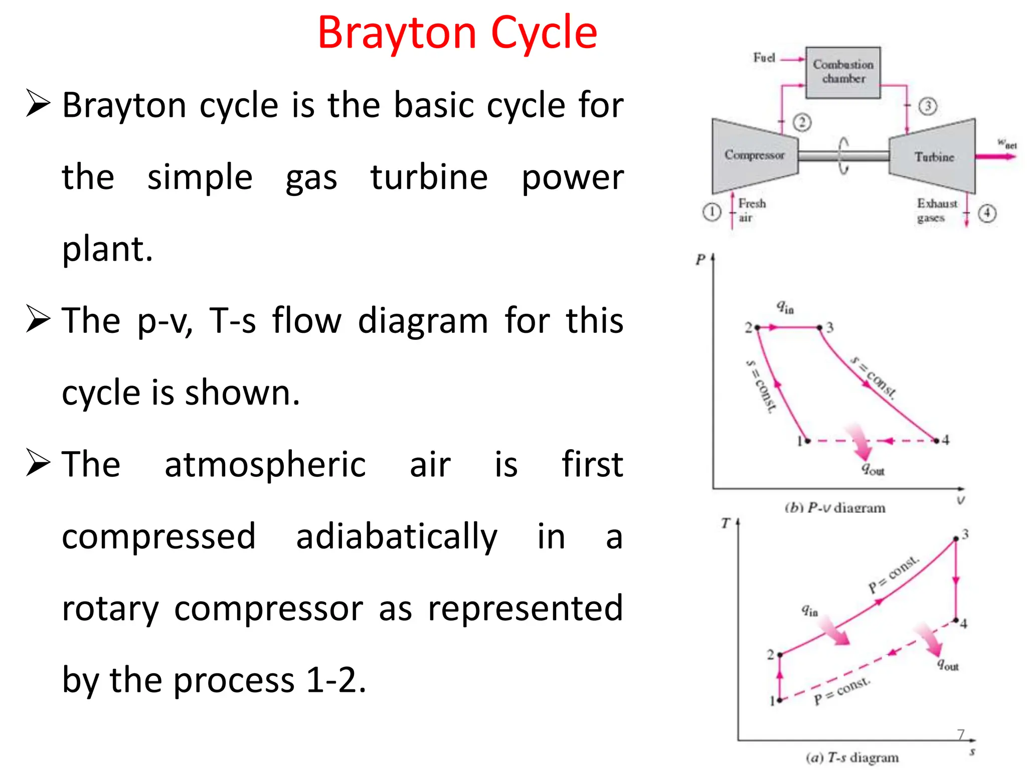
Gas turbine Engine
1
• A gas turbine, also called a combustion turbine, is a rotary
engine that extracts energy from a flow of combustion gas.
• It has an upstream compressor coupled to a downstream
turbine, and a combustion chamber in-between.
• Gas turbine may also refer to just the turbine component. Energy
is added to the gas stream in the combustor, where fuel is mixed
with air and ignited.
• In the high pressure environment of the combustor, combustion
of the fuel increases the temperature.
• The products of the combustion are forced into the turbine
section after passing through a nozzle and directed over the
turbine's blades.
• Due to high KE/Pressure energy of the products of combustion,
rotor of the turbine spins which powers the compressor and also
delivers the necessary power to the output shaft.
2
Classification of Gas turbines
(1) Based on type of combustion:
(i) Constant pressure combustion gas turbines cycles –
Example: Brayton cycle
Again it may be:
(a) Open type gas turbines
(b) Closed type gas turbines.
(ii) Constant volume combustion cycles – always open type
(Example: Ram Jet engine)
3
Merits of gas turbine over IC engines
• High Mechanical efficiency
• Fly wheel is not necessary
• High speeds are possible
• Due to expansion of gasses to the lowest
pressure work done per kg is more.
• Lower pressure ranges compared to IC engines
• Ignition, lubrication are simpler, cheaper fuels can
be used and no problem of knocking
• Due to lower specific weight suitable for aircraft
application.
4
Demerits:
• Lower thermal efficiency (20-25%) compared to
IC engines ( 20-30%)
• Speed reduction mechanisms are necessary.
• Difficult to start the gas turbine plant as
compared to IC engines
• Special cooling systems are necessary turbine
blades
• Poor Thermal efficiency at part load conditions
5
Assumptions for analysis of Ideal Gas Turbine Cycles: -
(i) Working substance is air and it behaves as a perfect gas.
(ii) Expansion and compression processes are isentropic.
(iii) No pressure losses in the piping connecting the various
components as well as in the heat exchangers.
(iv) Changes in KE and PE of the fluid are negligible.
(v) Flow through various components is one dimensional,
steady and uniform.
6
Brayton Cycle
 Brayton cycle is the basic cycle for
the simple gas turbine power
plant.
 The p-v, T-s flow diagram for this
cycle is shown.
 The atmospheric air is first
compressed adiabatically in a
rotary compressor as represented
by the process 1-2.
7
 The fuel is injected into the air stream and burnt at constant
pressure in the combustion chamber which is represented by
the process 2-3.
 The products of the combustion expanded isentropically in
the turbine back to the atmospheric pressure and exhausted
 The actual heat rejection take place in the open atmosphere
thus completing the cycle.
 The cycle is open.
 Thus there are two reversible isobar and two reversible
adiabatics.
8
The expression for thermal efficiency in terms of the
pressure ratio rp
Heat supplied Q1 = m (h3 – h2) = m Cp[T3 – T2]
Heat rejected Q2 = m (h4 – h1) = m Cp[T4 – T1]
For the reversible adiabatic process 1-2 we have,
𝑇2
𝑇1
=
𝑃2
𝑃1
𝛾−1
𝛾
= 𝑟𝑝
𝛾−1
𝛾
𝑇ℎ𝑒𝑟𝑚𝑎𝑙 𝑒𝑓𝑓𝑖𝑐𝑖𝑒𝑛𝑐𝑦 𝑜𝑟 𝐶𝑦𝑐𝑙𝑒 𝑒𝑓𝑓𝑖𝑐𝑒𝑖𝑛𝑐𝑦
𝜂𝑡ℎ𝑒𝑟𝑚𝑎𝑙 = 1 −
𝑄2
𝑄1
= 1 −
𝑚 𝐶𝑝 𝑇4 − 𝑇1
𝑚 𝐶𝑝 𝑇3 − 𝑇2
= 1 −
(𝑇4 − 𝑇1
(𝑇3 − 𝑇2
9
• For the reversible adiabatic process 3-4 we have,
𝑇3
𝑇4
=
𝑃3
𝑃4
𝛾−1
𝛾
= 𝑟𝑝
𝛾−1
𝛾
• Since P2 = P3 and P4 = P1
𝑇2
𝑇1
=
𝑃2
𝑃1
𝛾−1
𝛾
=
𝑇3
𝑇4
=
𝑃3
𝑃4
𝛾−1
𝛾
= 𝑟𝑝
𝛾−1
𝛾
• Thus,
𝑇2
𝑇1
=
𝑇3
𝑇4
→
𝑇4
𝑇1
=
𝑇3
𝑇2
→
𝑇4
𝑇1
− 1 =
𝑇3
𝑇2
− 1
𝑇4 − 𝑇1
𝑇1
=
𝑇3 − 𝑇2
𝑇2
𝑜𝑟
𝑇4 − 𝑇1
𝑇3 − 𝑇2
=
𝑇1
𝑇2
=
1
𝑟𝑝
𝛾−1
𝛾
• 𝜂𝑡ℎ𝑒𝑟𝑚𝑎𝑙 = 1 −
𝑇4−𝑇1
𝑇3−𝑇2
= 1 −
𝑇1
𝑇2
= 1 −
1
𝑟𝑝
𝛾−1
𝛾
10
• Thus the efficiency of the Brayton cycle depends upon
pressure ratio or compression ratio.
• For the same compression ratio, the Brayton cycle
efficiency is equal to the Otto cycle efficiency.
Effect of Irreversibilities in Turbines and Compressors
 The Brayton cycle is highly sensitive to the real machine
efficiencies of the turbine and compressor.
 The irreversibilities in the compression process result in
more work of compression compared to the theoretical
work required.(Isentropic efficiency of compressor)
 The actual work output is less than isentropic work of
expansion. (Isentropic efficiency of Turbine)
 The above two factors in total result in reduced net work.
11
• There are two types of losses
 Loss due to the irreversibilities
 Pressure drop during heat addition and heat rejection.
• 𝜂𝑇𝑢𝑟𝑏𝑖𝑛𝑒 =
ℎ3−ℎ4
ℎ3−ℎ4𝑠
=
(𝑇3−𝑇4
(𝑇3−𝑇4𝑠
• 𝜂𝐶𝑜𝑚𝑝𝑟𝑒𝑠𝑠𝑜𝑟 =
ℎ2𝑠−ℎ1
ℎ2−ℎ1
=
(𝑇2𝑠−𝑇1
(𝑇2−𝑇1
12
Methods to improve the efficiency and specific
output of simple cycle:
• The early gas turbines had simple-cycle efficiencies of
about 17% because of
 Low compressor and turbine efficiencies
 Low turbine inlet temperatures ( metallurgical limit).
Therefore, gas turbines were found only limited use
despite their versatility and their ability to burn a variety
of fuels.
There are three ways of improving the cycle efficiency:
 Increasing the turbine inlet temperatures.
 Increasing the machine efficiencies
 Modifications to the basic cycle. 13
Brayton cycle with regeneration (Cycle Modification)
 In gas-turbine engines, the temperature of the exhaust gas leaving
the turbine is higher than the temperature of the air leaving the
compressor.
 Therefore, the high-pressure air leaving the compressor can be
heated by transferring heat to it from the hot exhaust gases in a
counter-flow heat exchanger, which is also known as a regenerator.
 The thermal efficiency of the Brayton cycle increases
as a result of regeneration since the portion of
energy of the exhaust gases that is normally rejected
to the surroundings is now used to preheat the air
entering the combustion chamber.
14
 The thermal efficiency of the Brayton cycle increases as a result of
regeneration since the portion of energy of the exhaust gases that is
normally rejected to the surroundings is now used to preheat the air
entering the combustion chamber.
 This, in turn, decreases the heat input (thus fuel) requirements for the
same net work output.
 The use of a regenerator is recommended only when the turbine
exhaust temperature is higher than the compressor exit temperature,
otherwise, heat will flow in the reverse direction (to the exhaust gases),
decreasing the efficiency. This situation is encountered in gas turbines
operating at very high-pressure ratios.
15
 The temperature of air leaving the turbine at
4 is higher than that of air leaving the
compressor at 2.
 In the regenerator, the temperature of the of the
air leaving the compressor is raised by heat transfer
from exhaust gas.
 The maximum temperature to which the cold air at
2 could be heated is the temperature of the hot air
leaving the turbine (State 4) and actual
temperature attained is 5.
 The ratio of actual temperature rise to maximum possible temperature rise
is called as regenerator efficiency
16
 When regenerator is used in the Brayton cycle both heat supplied
 Mean temperature of heat addition increases and that of heat
rejection decreases due to regeneration hence efficiency increases,
with work output remains unchanged.
 Q1 actual = (h3-h5) = CP (T3-T5) & Q2 actual= (h6 - h1) = CP (T6 -T1)
 Turbine work = (h3-h4) = CP (T3-T4)
 𝜂𝑡ℎ𝑒𝑟𝑚𝑎𝑙 = 1 −
𝑄2
𝑄1
= 1 −
(𝑇6−𝑇1
(𝑇3−𝑇5
 𝜂𝑅𝑒 =
𝐴𝑐𝑡𝑢𝑎𝑙 𝐻𝑇 𝑖𝑛 𝑡ℎ𝑒 𝑟𝑒𝑔𝑒𝑛𝑒𝑟𝑎𝑡𝑜𝑟
𝑀𝑎𝑥𝑖𝑚𝑢𝑚 𝑝𝑜𝑠𝑠𝑖𝑏𝑙𝑒 𝐻𝑇
=
ℎ5 − ℎ2
ℎ4 − ℎ2
=
(𝑇5 − 𝑇2
(𝑇4 − 𝑇2
17
• The net work output of a gas-turbine cycle is the difference between
the turbine work output and the compressor work input.
• The net work can be increased by either decreasing the compressor
work or increasing the turbine work, or both.
• The work required to compress the gas between two specified
pressures can be decreased by carrying out the compression process
in stages and cooling the gas in between the stages (multistage
compression with inter-cooling).
• As the number of stages is increased, the compression process
becomes nearly isothermal at the compressor inlet temperature, and
the compression work decreases. 18
• The work output of a turbine operating between two given
pressure levels can be increased by expanding the gas in stages
and reheating it in between the stages (multistage expansion with
reheating) for a given metallurgical limits.
• Combustion in gas turbines typically occurs at very high A/F ratio
(50-75) compared to stoichiometric A/F ratio.
• Thus the products of combustion contains excess air ( sufficient
amount of Oxygen) and reheating can be done by simply spraying
additional fuel into the exhaust gases between two expansion
stages.
19
• The multistage expansion with reheating results in increased
specific work output, however with increased heat transfer. Hence
efficiency may not increase.
• The multi stage expansion with reheating results in increased
exhaust gas temperature.
• Higher exhaust gas temperature due to multistage expansion and
reheating makes the regeneration process more attractive.
• Thus multistage expansion with reheating, regeneration and
multistage compression along with intercooling results in increased
efficiency and specific power output.
20
A schematic diagram two stage compression with intercooling and two
stage expansion with reheating along with regeneration
Process 1-2 Reversible adiabatic compression in the LP stage
Process 3-4 Reversible adiabatic compression in the HP stage.
Process 5-6 Constant pressure heat addition in the CC.
Process 7-8 Constant pressure reheating in the re-heater
Process 9-10 Constant pressure heat loss from the products
of combustion to compressed air from LP stage
Process 2-3 Constant pressure intercooling.
Process 4-5 Constant pressure heat recovery
or regeneration.
Process 6-7 Reversible adiabatic expansion
in the HP stage
Process 8-9 Reversible adiabatic expansion
process 21
• The working substance which is air enters the first stage
of the compressor ( LP stage) at state 1, is compressed
isentropically to an intermediate pressure P2.
• The compressed gas or air is then cooled at constant
pressure to state 3 (T3 = T1).
• It is then compressed in the second stage (HP stage)
isentropically to the final pressure P4.
• At state 4 the gas enters the regenerator, where it is
heated to T5 at constant pressure using exhaust gasses
from LP turbine.
• In an ideal regenerator, the gas leaves the regenerator at
the temperature of the turbine exhaust, that is, T5 =T9.
22
• The primary heat addition (or combustion) process
takes place between states 5 and 6.
• The gas enters the first stage of the turbine at state 6
and expands isentropically to state 7.
• The partially expanded gasses are reheated at constant
pressure from state 7 to state 8 (T8 = T6 under ideal
condition).
• Finally reheated combustion products are expanded in
the second stage of the turbine through an isentropic
process 8-9.
• The gas exits the turbine at state 9 and enters the
regenerator, where it is cooled to state 10 at constant
pressure.
• The cycle is completed
23
Thermodynamic analysis of two- stage compression,
two-stage expansion with regeneration
• Assuming perfect intercooling without pressure loss so that P2 = P3
and
𝑃2
𝑃1
=
𝑃4
𝑃3
𝑇3 = 𝑇1
• Similarly for ideal the regeneration T5 = T9 = T7 and T4 = T2 = T10
• When the reheating is considered as ideal, T6 = T8
• Total heat supplied = HS in the CC+ HS in the re-heater
𝑄1= 𝐶𝑃 ∗ 𝑇6 − 𝑇5 + 𝐶𝑃 ∗ 𝑇8 − 𝑇7
• 𝑆𝑖𝑛𝑐𝑒 𝑇6 = 𝑇8 𝑎𝑛𝑑 𝑇5 = 𝑇7, 𝑤𝑒 𝑔𝑒𝑡 𝑄1 = 2 ∗ 𝐶𝑃 ∗ 𝑇6 − 𝑇7
• Total heat rejected = HR in the process 10-1 + HR in the intercooler
𝑄2 = 𝐶𝑃 ∗ 𝑇10 − 𝑇1 + 𝐶𝑃 ∗ 𝑇2 − 𝑇3 24
• 𝑆𝑖𝑛𝑐𝑒 𝑇3 = 𝑇1 𝑎𝑛𝑑 𝑇10 = 𝑇2 𝑄2 = 2 ∗ 𝐶𝑃 ∗
𝑇2 − 𝑇1
• 𝑊𝑛𝑒𝑡 = 𝑄1 − 𝑄2 = 2 ∗ 𝐶𝑃∗ 𝑇6 − 𝑇7 − 𝑇2 − 𝑇1
• 𝜂𝐶𝑦𝑐𝑙𝑒 =
𝑊𝑛𝑒𝑡
𝑄1
=
=2∗𝐶𝑃∗ 𝑇6−𝑇7 − 𝑇2−𝑇1
2∗𝐶𝑃∗ 𝑇6−𝑇7
= 1 −
𝑇2−𝑇1
𝑇6−𝑇7
• 𝜂𝐶𝑦𝑐𝑙𝑒 = 1 −
𝑇2−𝑇1
𝑇6−𝑇7
= 1 −
𝑇1
𝑇6
𝑇2
𝑇1
−1
1−
𝑇7
𝑇6
• But we have
𝑇2
𝑇1
− 1 =
𝑃2
𝑃1
𝛾−1
𝛾 − 1 = 𝑟𝑝𝑠
𝛾−1
𝛾 − 1
25
• 𝑊𝑒 ℎ𝑎𝑣𝑒
𝑃6
𝑃7
=
𝑃8
𝑃9
=
𝑃4
𝑃3
=
𝑃2
𝑃1
= 𝑟𝑝𝑠 = 𝑆𝑡𝑎𝑔𝑒 𝑝𝑟𝑒𝑠𝑠𝑢𝑟𝑒 𝑟𝑎𝑡𝑖𝑜
• 1 −
𝑇7
𝑇6
= 1 −
𝑃7
𝑃6
𝛾−1
𝛾 = 1 −
1
𝑟𝑝𝑠
𝛾−1
𝛾
=
𝑟𝑝𝑠
𝛾−1
𝛾 −1
𝑟𝑝𝑠
𝛾−1
𝛾
•
𝑇2
𝑇1
−1
1−
𝑇7
𝑇6
=
𝑟𝑝𝑠
𝛾−1
𝛾 −1
𝑟𝑝𝑠
𝛾−1
𝛾 −1
𝑟𝑝𝑠
𝛾−1
𝛾
= 𝑟𝑝𝑠
𝛾−1
𝛾 =
𝑃2
𝑃1
𝛾−1
𝛾
• 𝜂𝐶𝑦𝑐𝑙𝑒 = 1 −
𝑇2−𝑇1
𝑇6−𝑇7
= 1 −
𝑇1
𝑇6
𝑃2
𝑃1
𝛾−1
𝛾
• 𝜂𝐶𝑦𝑐𝑙𝑒 = 1 −
𝑀𝑖𝑛𝑖𝑚𝑢𝑚 𝑇𝑒𝑚𝑝𝑒𝑟𝑎𝑡𝑢𝑟𝑒 𝑜𝑓 𝑡ℎ𝑒 𝑐𝑦𝑐𝑙𝑒
𝑀𝑎𝑥𝑖𝑚𝑢𝑚 𝑇𝑒𝑚𝑝𝑒𝑟𝑎𝑡𝑢𝑟𝑒 𝑜𝑓 𝑡ℎ𝑒 𝑐𝑦𝑐𝑙𝑒
∗ 𝑆𝑡𝑎𝑔𝑒 𝑝𝑟𝑒𝑠𝑠𝑢𝑟𝑒 𝑟𝑎𝑡𝑖𝑜
𝛾−1
𝛾
26

gas turbine cycles.pptx .

  • 1.
  • 2.
    • A gasturbine, also called a combustion turbine, is a rotary engine that extracts energy from a flow of combustion gas. • It has an upstream compressor coupled to a downstream turbine, and a combustion chamber in-between. • Gas turbine may also refer to just the turbine component. Energy is added to the gas stream in the combustor, where fuel is mixed with air and ignited. • In the high pressure environment of the combustor, combustion of the fuel increases the temperature. • The products of the combustion are forced into the turbine section after passing through a nozzle and directed over the turbine's blades. • Due to high KE/Pressure energy of the products of combustion, rotor of the turbine spins which powers the compressor and also delivers the necessary power to the output shaft. 2
  • 3.
    Classification of Gasturbines (1) Based on type of combustion: (i) Constant pressure combustion gas turbines cycles – Example: Brayton cycle Again it may be: (a) Open type gas turbines (b) Closed type gas turbines. (ii) Constant volume combustion cycles – always open type (Example: Ram Jet engine) 3
  • 4.
    Merits of gasturbine over IC engines • High Mechanical efficiency • Fly wheel is not necessary • High speeds are possible • Due to expansion of gasses to the lowest pressure work done per kg is more. • Lower pressure ranges compared to IC engines • Ignition, lubrication are simpler, cheaper fuels can be used and no problem of knocking • Due to lower specific weight suitable for aircraft application. 4
  • 5.
    Demerits: • Lower thermalefficiency (20-25%) compared to IC engines ( 20-30%) • Speed reduction mechanisms are necessary. • Difficult to start the gas turbine plant as compared to IC engines • Special cooling systems are necessary turbine blades • Poor Thermal efficiency at part load conditions 5
  • 6.
    Assumptions for analysisof Ideal Gas Turbine Cycles: - (i) Working substance is air and it behaves as a perfect gas. (ii) Expansion and compression processes are isentropic. (iii) No pressure losses in the piping connecting the various components as well as in the heat exchangers. (iv) Changes in KE and PE of the fluid are negligible. (v) Flow through various components is one dimensional, steady and uniform. 6
  • 7.
    Brayton Cycle  Braytoncycle is the basic cycle for the simple gas turbine power plant.  The p-v, T-s flow diagram for this cycle is shown.  The atmospheric air is first compressed adiabatically in a rotary compressor as represented by the process 1-2. 7
  • 8.
     The fuelis injected into the air stream and burnt at constant pressure in the combustion chamber which is represented by the process 2-3.  The products of the combustion expanded isentropically in the turbine back to the atmospheric pressure and exhausted  The actual heat rejection take place in the open atmosphere thus completing the cycle.  The cycle is open.  Thus there are two reversible isobar and two reversible adiabatics. 8
  • 9.
    The expression forthermal efficiency in terms of the pressure ratio rp Heat supplied Q1 = m (h3 – h2) = m Cp[T3 – T2] Heat rejected Q2 = m (h4 – h1) = m Cp[T4 – T1] For the reversible adiabatic process 1-2 we have, 𝑇2 𝑇1 = 𝑃2 𝑃1 𝛾−1 𝛾 = 𝑟𝑝 𝛾−1 𝛾 𝑇ℎ𝑒𝑟𝑚𝑎𝑙 𝑒𝑓𝑓𝑖𝑐𝑖𝑒𝑛𝑐𝑦 𝑜𝑟 𝐶𝑦𝑐𝑙𝑒 𝑒𝑓𝑓𝑖𝑐𝑒𝑖𝑛𝑐𝑦 𝜂𝑡ℎ𝑒𝑟𝑚𝑎𝑙 = 1 − 𝑄2 𝑄1 = 1 − 𝑚 𝐶𝑝 𝑇4 − 𝑇1 𝑚 𝐶𝑝 𝑇3 − 𝑇2 = 1 − (𝑇4 − 𝑇1 (𝑇3 − 𝑇2 9
  • 10.
    • For thereversible adiabatic process 3-4 we have, 𝑇3 𝑇4 = 𝑃3 𝑃4 𝛾−1 𝛾 = 𝑟𝑝 𝛾−1 𝛾 • Since P2 = P3 and P4 = P1 𝑇2 𝑇1 = 𝑃2 𝑃1 𝛾−1 𝛾 = 𝑇3 𝑇4 = 𝑃3 𝑃4 𝛾−1 𝛾 = 𝑟𝑝 𝛾−1 𝛾 • Thus, 𝑇2 𝑇1 = 𝑇3 𝑇4 → 𝑇4 𝑇1 = 𝑇3 𝑇2 → 𝑇4 𝑇1 − 1 = 𝑇3 𝑇2 − 1 𝑇4 − 𝑇1 𝑇1 = 𝑇3 − 𝑇2 𝑇2 𝑜𝑟 𝑇4 − 𝑇1 𝑇3 − 𝑇2 = 𝑇1 𝑇2 = 1 𝑟𝑝 𝛾−1 𝛾 • 𝜂𝑡ℎ𝑒𝑟𝑚𝑎𝑙 = 1 − 𝑇4−𝑇1 𝑇3−𝑇2 = 1 − 𝑇1 𝑇2 = 1 − 1 𝑟𝑝 𝛾−1 𝛾 10
  • 11.
    • Thus theefficiency of the Brayton cycle depends upon pressure ratio or compression ratio. • For the same compression ratio, the Brayton cycle efficiency is equal to the Otto cycle efficiency. Effect of Irreversibilities in Turbines and Compressors  The Brayton cycle is highly sensitive to the real machine efficiencies of the turbine and compressor.  The irreversibilities in the compression process result in more work of compression compared to the theoretical work required.(Isentropic efficiency of compressor)  The actual work output is less than isentropic work of expansion. (Isentropic efficiency of Turbine)  The above two factors in total result in reduced net work. 11
  • 12.
    • There aretwo types of losses  Loss due to the irreversibilities  Pressure drop during heat addition and heat rejection. • 𝜂𝑇𝑢𝑟𝑏𝑖𝑛𝑒 = ℎ3−ℎ4 ℎ3−ℎ4𝑠 = (𝑇3−𝑇4 (𝑇3−𝑇4𝑠 • 𝜂𝐶𝑜𝑚𝑝𝑟𝑒𝑠𝑠𝑜𝑟 = ℎ2𝑠−ℎ1 ℎ2−ℎ1 = (𝑇2𝑠−𝑇1 (𝑇2−𝑇1 12
  • 13.
    Methods to improvethe efficiency and specific output of simple cycle: • The early gas turbines had simple-cycle efficiencies of about 17% because of  Low compressor and turbine efficiencies  Low turbine inlet temperatures ( metallurgical limit). Therefore, gas turbines were found only limited use despite their versatility and their ability to burn a variety of fuels. There are three ways of improving the cycle efficiency:  Increasing the turbine inlet temperatures.  Increasing the machine efficiencies  Modifications to the basic cycle. 13
  • 14.
    Brayton cycle withregeneration (Cycle Modification)  In gas-turbine engines, the temperature of the exhaust gas leaving the turbine is higher than the temperature of the air leaving the compressor.  Therefore, the high-pressure air leaving the compressor can be heated by transferring heat to it from the hot exhaust gases in a counter-flow heat exchanger, which is also known as a regenerator.  The thermal efficiency of the Brayton cycle increases as a result of regeneration since the portion of energy of the exhaust gases that is normally rejected to the surroundings is now used to preheat the air entering the combustion chamber. 14
  • 15.
     The thermalefficiency of the Brayton cycle increases as a result of regeneration since the portion of energy of the exhaust gases that is normally rejected to the surroundings is now used to preheat the air entering the combustion chamber.  This, in turn, decreases the heat input (thus fuel) requirements for the same net work output.  The use of a regenerator is recommended only when the turbine exhaust temperature is higher than the compressor exit temperature, otherwise, heat will flow in the reverse direction (to the exhaust gases), decreasing the efficiency. This situation is encountered in gas turbines operating at very high-pressure ratios. 15
  • 16.
     The temperatureof air leaving the turbine at 4 is higher than that of air leaving the compressor at 2.  In the regenerator, the temperature of the of the air leaving the compressor is raised by heat transfer from exhaust gas.  The maximum temperature to which the cold air at 2 could be heated is the temperature of the hot air leaving the turbine (State 4) and actual temperature attained is 5.  The ratio of actual temperature rise to maximum possible temperature rise is called as regenerator efficiency 16
  • 17.
     When regeneratoris used in the Brayton cycle both heat supplied  Mean temperature of heat addition increases and that of heat rejection decreases due to regeneration hence efficiency increases, with work output remains unchanged.  Q1 actual = (h3-h5) = CP (T3-T5) & Q2 actual= (h6 - h1) = CP (T6 -T1)  Turbine work = (h3-h4) = CP (T3-T4)  𝜂𝑡ℎ𝑒𝑟𝑚𝑎𝑙 = 1 − 𝑄2 𝑄1 = 1 − (𝑇6−𝑇1 (𝑇3−𝑇5  𝜂𝑅𝑒 = 𝐴𝑐𝑡𝑢𝑎𝑙 𝐻𝑇 𝑖𝑛 𝑡ℎ𝑒 𝑟𝑒𝑔𝑒𝑛𝑒𝑟𝑎𝑡𝑜𝑟 𝑀𝑎𝑥𝑖𝑚𝑢𝑚 𝑝𝑜𝑠𝑠𝑖𝑏𝑙𝑒 𝐻𝑇 = ℎ5 − ℎ2 ℎ4 − ℎ2 = (𝑇5 − 𝑇2 (𝑇4 − 𝑇2 17
  • 18.
    • The network output of a gas-turbine cycle is the difference between the turbine work output and the compressor work input. • The net work can be increased by either decreasing the compressor work or increasing the turbine work, or both. • The work required to compress the gas between two specified pressures can be decreased by carrying out the compression process in stages and cooling the gas in between the stages (multistage compression with inter-cooling). • As the number of stages is increased, the compression process becomes nearly isothermal at the compressor inlet temperature, and the compression work decreases. 18
  • 19.
    • The workoutput of a turbine operating between two given pressure levels can be increased by expanding the gas in stages and reheating it in between the stages (multistage expansion with reheating) for a given metallurgical limits. • Combustion in gas turbines typically occurs at very high A/F ratio (50-75) compared to stoichiometric A/F ratio. • Thus the products of combustion contains excess air ( sufficient amount of Oxygen) and reheating can be done by simply spraying additional fuel into the exhaust gases between two expansion stages. 19
  • 20.
    • The multistageexpansion with reheating results in increased specific work output, however with increased heat transfer. Hence efficiency may not increase. • The multi stage expansion with reheating results in increased exhaust gas temperature. • Higher exhaust gas temperature due to multistage expansion and reheating makes the regeneration process more attractive. • Thus multistage expansion with reheating, regeneration and multistage compression along with intercooling results in increased efficiency and specific power output. 20
  • 21.
    A schematic diagramtwo stage compression with intercooling and two stage expansion with reheating along with regeneration Process 1-2 Reversible adiabatic compression in the LP stage Process 3-4 Reversible adiabatic compression in the HP stage. Process 5-6 Constant pressure heat addition in the CC. Process 7-8 Constant pressure reheating in the re-heater Process 9-10 Constant pressure heat loss from the products of combustion to compressed air from LP stage Process 2-3 Constant pressure intercooling. Process 4-5 Constant pressure heat recovery or regeneration. Process 6-7 Reversible adiabatic expansion in the HP stage Process 8-9 Reversible adiabatic expansion process 21
  • 22.
    • The workingsubstance which is air enters the first stage of the compressor ( LP stage) at state 1, is compressed isentropically to an intermediate pressure P2. • The compressed gas or air is then cooled at constant pressure to state 3 (T3 = T1). • It is then compressed in the second stage (HP stage) isentropically to the final pressure P4. • At state 4 the gas enters the regenerator, where it is heated to T5 at constant pressure using exhaust gasses from LP turbine. • In an ideal regenerator, the gas leaves the regenerator at the temperature of the turbine exhaust, that is, T5 =T9. 22
  • 23.
    • The primaryheat addition (or combustion) process takes place between states 5 and 6. • The gas enters the first stage of the turbine at state 6 and expands isentropically to state 7. • The partially expanded gasses are reheated at constant pressure from state 7 to state 8 (T8 = T6 under ideal condition). • Finally reheated combustion products are expanded in the second stage of the turbine through an isentropic process 8-9. • The gas exits the turbine at state 9 and enters the regenerator, where it is cooled to state 10 at constant pressure. • The cycle is completed 23
  • 24.
    Thermodynamic analysis oftwo- stage compression, two-stage expansion with regeneration • Assuming perfect intercooling without pressure loss so that P2 = P3 and 𝑃2 𝑃1 = 𝑃4 𝑃3 𝑇3 = 𝑇1 • Similarly for ideal the regeneration T5 = T9 = T7 and T4 = T2 = T10 • When the reheating is considered as ideal, T6 = T8 • Total heat supplied = HS in the CC+ HS in the re-heater 𝑄1= 𝐶𝑃 ∗ 𝑇6 − 𝑇5 + 𝐶𝑃 ∗ 𝑇8 − 𝑇7 • 𝑆𝑖𝑛𝑐𝑒 𝑇6 = 𝑇8 𝑎𝑛𝑑 𝑇5 = 𝑇7, 𝑤𝑒 𝑔𝑒𝑡 𝑄1 = 2 ∗ 𝐶𝑃 ∗ 𝑇6 − 𝑇7 • Total heat rejected = HR in the process 10-1 + HR in the intercooler 𝑄2 = 𝐶𝑃 ∗ 𝑇10 − 𝑇1 + 𝐶𝑃 ∗ 𝑇2 − 𝑇3 24
  • 25.
    • 𝑆𝑖𝑛𝑐𝑒 𝑇3= 𝑇1 𝑎𝑛𝑑 𝑇10 = 𝑇2 𝑄2 = 2 ∗ 𝐶𝑃 ∗ 𝑇2 − 𝑇1 • 𝑊𝑛𝑒𝑡 = 𝑄1 − 𝑄2 = 2 ∗ 𝐶𝑃∗ 𝑇6 − 𝑇7 − 𝑇2 − 𝑇1 • 𝜂𝐶𝑦𝑐𝑙𝑒 = 𝑊𝑛𝑒𝑡 𝑄1 = =2∗𝐶𝑃∗ 𝑇6−𝑇7 − 𝑇2−𝑇1 2∗𝐶𝑃∗ 𝑇6−𝑇7 = 1 − 𝑇2−𝑇1 𝑇6−𝑇7 • 𝜂𝐶𝑦𝑐𝑙𝑒 = 1 − 𝑇2−𝑇1 𝑇6−𝑇7 = 1 − 𝑇1 𝑇6 𝑇2 𝑇1 −1 1− 𝑇7 𝑇6 • But we have 𝑇2 𝑇1 − 1 = 𝑃2 𝑃1 𝛾−1 𝛾 − 1 = 𝑟𝑝𝑠 𝛾−1 𝛾 − 1 25
  • 26.
    • 𝑊𝑒 ℎ𝑎𝑣𝑒 𝑃6 𝑃7 = 𝑃8 𝑃9 = 𝑃4 𝑃3 = 𝑃2 𝑃1 =𝑟𝑝𝑠 = 𝑆𝑡𝑎𝑔𝑒 𝑝𝑟𝑒𝑠𝑠𝑢𝑟𝑒 𝑟𝑎𝑡𝑖𝑜 • 1 − 𝑇7 𝑇6 = 1 − 𝑃7 𝑃6 𝛾−1 𝛾 = 1 − 1 𝑟𝑝𝑠 𝛾−1 𝛾 = 𝑟𝑝𝑠 𝛾−1 𝛾 −1 𝑟𝑝𝑠 𝛾−1 𝛾 • 𝑇2 𝑇1 −1 1− 𝑇7 𝑇6 = 𝑟𝑝𝑠 𝛾−1 𝛾 −1 𝑟𝑝𝑠 𝛾−1 𝛾 −1 𝑟𝑝𝑠 𝛾−1 𝛾 = 𝑟𝑝𝑠 𝛾−1 𝛾 = 𝑃2 𝑃1 𝛾−1 𝛾 • 𝜂𝐶𝑦𝑐𝑙𝑒 = 1 − 𝑇2−𝑇1 𝑇6−𝑇7 = 1 − 𝑇1 𝑇6 𝑃2 𝑃1 𝛾−1 𝛾 • 𝜂𝐶𝑦𝑐𝑙𝑒 = 1 − 𝑀𝑖𝑛𝑖𝑚𝑢𝑚 𝑇𝑒𝑚𝑝𝑒𝑟𝑎𝑡𝑢𝑟𝑒 𝑜𝑓 𝑡ℎ𝑒 𝑐𝑦𝑐𝑙𝑒 𝑀𝑎𝑥𝑖𝑚𝑢𝑚 𝑇𝑒𝑚𝑝𝑒𝑟𝑎𝑡𝑢𝑟𝑒 𝑜𝑓 𝑡ℎ𝑒 𝑐𝑦𝑐𝑙𝑒 ∗ 𝑆𝑡𝑎𝑔𝑒 𝑝𝑟𝑒𝑠𝑠𝑢𝑟𝑒 𝑟𝑎𝑡𝑖𝑜 𝛾−1 𝛾 26