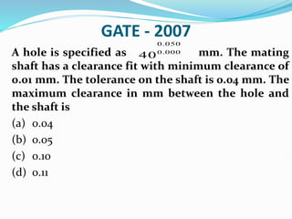
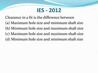
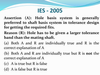
Download to read offline

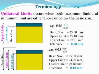

![Tolerance Designation (ISO)
Tolerance on a shaft or a hole can also be calculated by
using the formulas provided by ISO.
i
K
T
where,
T is the tolerance (in µm)
D
D
i 001
.
0
45
.
0 3
(unit tolerance, in µm)
2
1D
D
D (D1 and D2 are the nominal sizes marking
the beginning and the end of a range of
sizes, in mm)
6
6
.
1
10 IT
ITn
K
[For IT6 to IT16]](https://image.slidesharecdn.com/ch-24limittolerancefits-240121161422-fbdcbee9/85/Ch-24-Limit-Tolerance-Fits-pptx-32-320.jpg)
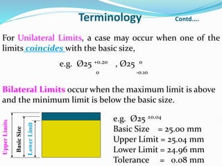
![IES-2006 Conventional
Find the limit sizes, tolerances and allowances for a
100 mm diameter shaft and hole pair designated by
F8h10. Also specify the type of fit that the above pair
belongs to.
Given: 100 mm diameter lies in the diameter step
range of 80-120 mm. The fundamental deviation for
shaft designation ‘f’ is -5.5 D0.41
The values of standard tolerances for grades of IT 8
and IT 10 are 25i and 64i respectively.
Also, indicate the limits and tolerance on a diagram.
[15-Marks]](https://image.slidesharecdn.com/ch-24limittolerancefits-240121161422-fbdcbee9/85/Ch-24-Limit-Tolerance-Fits-pptx-41-320.jpg)
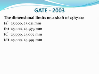

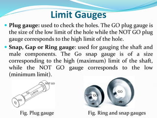
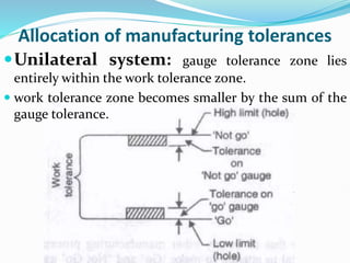
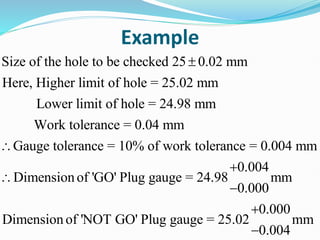
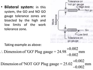


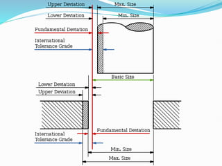
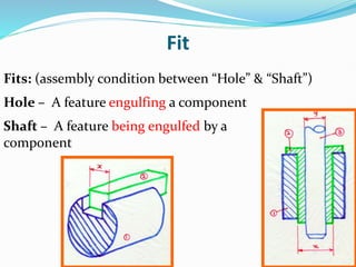
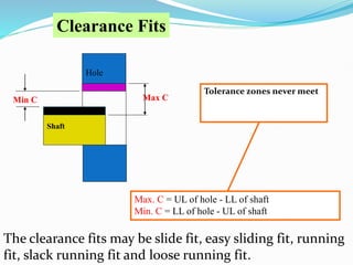
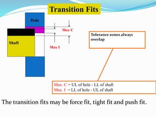
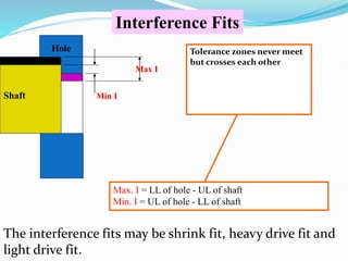
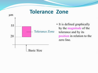
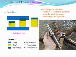
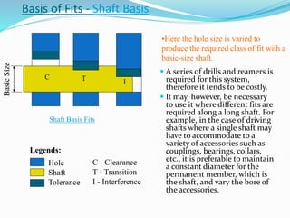
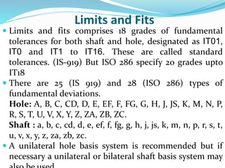
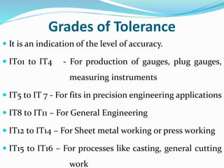
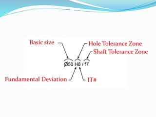
- Limits, tolerances, and fits refer to permissible variations in part dimensions to enable interchangeability. - A tolerance is the acceptable range between an upper and lower limit. It allows for manufacturing variability. - Fits include clearance, transition, and interference fits depending on whether tolerance zones overlap or not. - Hole and shaft basis refer to specifying tolerances relative to the hole or shaft dimension as a reference. - Standard tolerances grades like IT01 to IT16 indicate the accuracy level needed for the application.


