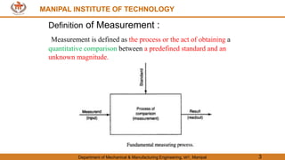
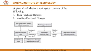
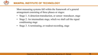
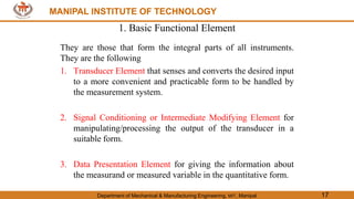
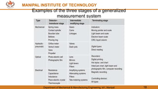
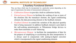
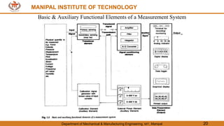
The document discusses measurement systems and their components. It describes how a generalized measurement system consists of three main elements - a transducer element that senses the input, a signal conditioning element that processes the output, and a data presentation element that provides the measurement results. It provides examples of different types of transducers and measurement instruments, and explains the desirable characteristics of transducer elements, including being sensitive only to the desired input and providing an accurate electrical output signal.


![MANIPAL INSTITUTE OF TECHNOLOGY
Department of Mechanical & Manufacturing Engineering, MIT, Manipal 79
MANIPAL INSTITUTE OF TECHNOLOGY
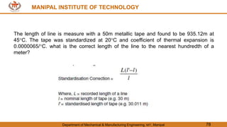
Correction =
935.12 [ (50 + 50 x 0.0000065 x 25) −50]
50
= 0.151957 m
Actual Length = Lm + correction = 935.12 + 0.151957
= 935.272m](https://image.slidesharecdn.com/measurementsmeasurementsystems-240314065341-2ec319b5/85/Measurements-Measurement-Systems-pptx-72-320.jpg)