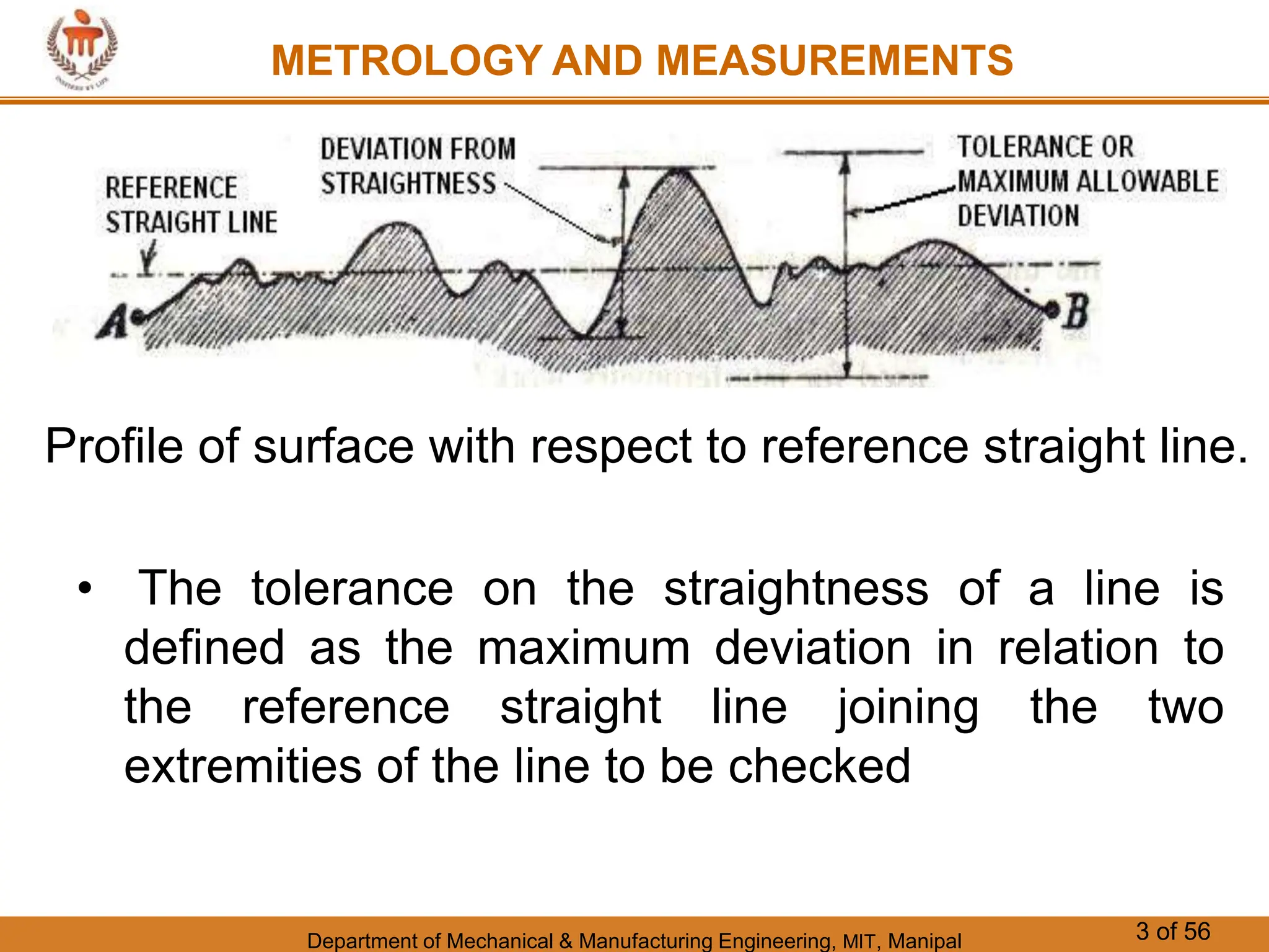
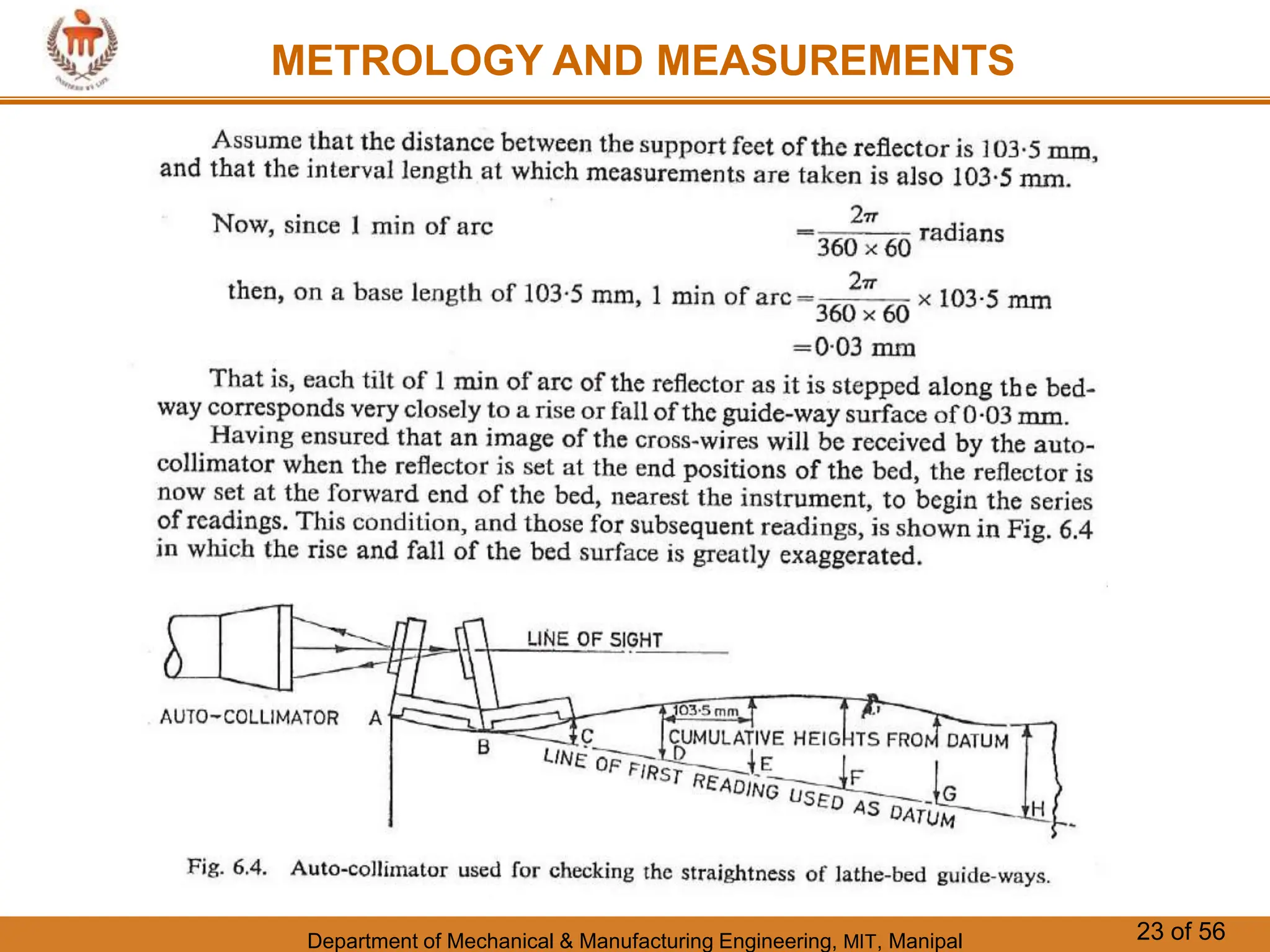
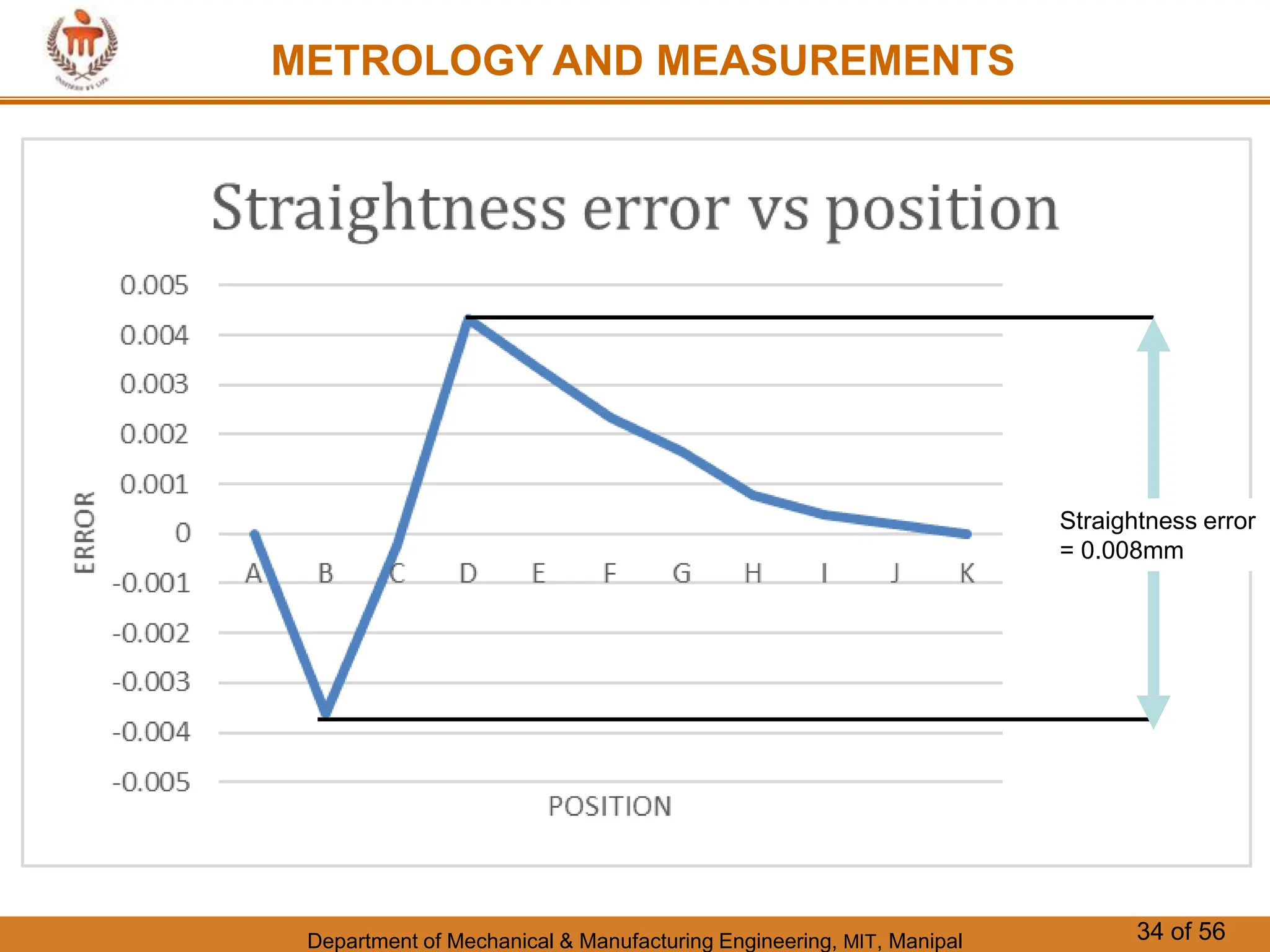
1. Department of Mechanical & Manufacturing Engineering, MIT, Manipal 1 of 56
METROLOGY AND MEASUREMENTS
CHAPTER 9
Measurement of Form Errors
2. Department of Mechanical & Manufacturing Engineering, MIT, Manipal 3 of 56
METROLOGY AND MEASUREMENTS
• The tolerance on the straightness of a line is
defined as the maximum deviation in relation to
the reference straight line joining the two
extremities of the line to be checked
Profile of surface with respect to reference straight line.
3. Department of Mechanical & Manufacturing Engineering, MIT, Manipal 5 of 56
METROLOGY AND MEASUREMENTS
Test for Straightness by using Spirit Level and
Auto-collimator
Tests for straightness can be carried out by using
spirit level or auto-collimator. The straightness of any
surface could be determined by either of these
instruments by measuring the relative angular
positions of number of adjacent sections of the
surface to be tested.
So first a straight line is drawn on the surface whose
straightness is to be tested.
4. Department of Mechanical & Manufacturing Engineering, MIT, Manipal 6 of 56
METROLOGY AND MEASUREMENTS
Spirit Level
5. Department of Mechanical & Manufacturing Engineering, MIT, Manipal 7 of 56
METROLOGY AND MEASUREMENTS
Then it is divided into, a number of sections, the length
of each section being equal to the length of spirit level
base or the plane reflector's base in case of auto-
collimator. Generally the bases of the spirit level block
or reflector are fitted with two feet so that only feet have
line contact with the surface and whole of the surface of
base does not touch the surface to be tested. This
ensures that angular deviation obtained is between the
specified two points. In this case length of each section
must be equal to distance between the centre lines of
two feet.
6. Department of Mechanical & Manufacturing Engineering, MIT, Manipal 8 of 56
METROLOGY AND MEASUREMENTS
The spirit level can be used only for the measurement
of straightness of horizontal surfaces while auto-
collimator method can be used on surfaces in any
plane.
In case of spirit level, the block is moved along the line
on the surface to be tested in steps equal to the pitch
distance between the centre lines of the feet and the
angular variations of the direction of block are
measured by the sensitive level on it.
Angular variation can be correlated in terms of the
difference of height between two points by knowing the
least count of level and length of the base.
7. Department of Mechanical & Manufacturing Engineering, MIT, Manipal 9 of 56
METROLOGY AND MEASUREMENTS
Straight Edge
A straight edge is a measuring tool which consists of a
length of a steel of narrow and deep section in order
to provide considerable resistance to bending in the
plane of measurement without excessive weight.
Precision straight edges are generally hardened and
lapped on edge only to a small radius in cross-section,
forming a blunt knife edge which is straight to a few
thousandths of a millimetre.
8. Department of Mechanical & Manufacturing Engineering, MIT, Manipal 10 of 56
METROLOGY AND MEASUREMENTS
A triangular architect's scale
Straight Edge
9. Department of Mechanical & Manufacturing Engineering, MIT, Manipal 11 of 56
METROLOGY AND MEASUREMENTS
For checking the straightness of any surface, the straight
edge is placed over the surface and two are viewed
against the light, which clearly indicates the straightness.
Usually the gap between the straight edge and surface
will be negligibly small for perfect straight surfaces and a
quantitative measure of straightness could be had by
observing the colour of light due to interference caused
by diffraction of light while passing through the small
gap.
If the colour of light be red, it indicates a gap of 0.0012
to 0.0017mm, while for blue light, the gap is
approximately 0.00075mm.
10. Department of Mechanical & Manufacturing Engineering, MIT, Manipal 12 of 56
METROLOGY AND MEASUREMENTS
Autocollimator
11. Department of Mechanical & Manufacturing Engineering, MIT, Manipal 13 of 56
METROLOGY AND MEASUREMENTS
Autocollimator:
In case of measurement by auto-collimator, the
instrument is placed at a distance of 0.5 to 0.75 meter
from the surface to be tested on any rigid support which
is independent of the surface to be tested.
The parallel beam from the instrument is projected
along the length of the surface to be tested.
A block fixed on two feet and fitted with a plane vertical
reflector is placed on the surface and the reflector face
is facing the instrument.
12. Department of Mechanical & Manufacturing Engineering, MIT, Manipal 14 of 56
METROLOGY AND MEASUREMENTS
13. Department of Mechanical & Manufacturing Engineering, MIT, Manipal 15 of 56
METROLOGY AND MEASUREMENTS
The reflector and the instrument are set such that the
image of the cross wires of the collimator appears
nearer the centre of the field and for the complete
movement of reflector along the surface straight line,
the image of cross-wires will appear in the field of
eyepiece, the reflector is then moved to the other end
of the surface in steps equal to the centre distance
between the feet and the tilt of the reflector is noted
down in second from the eyepiece.
The autocollimator projects a beam of collimated light.
An external reflector reflects all or part of the beam
back into the instrument where the beam is focused
and detected by a photo detector.
14. Department of Mechanical & Manufacturing Engineering, MIT, Manipal 16 of 56
METROLOGY AND MEASUREMENTS
The autocollimator measures the deviation between the
emitted beam and the reflected beam.
Because the autocollimator uses light to measure
angles, it never comes into contact with the test
surface.
Visual autocollimators rely on the operator's eye to act
as the photo detector. Micro-Radian visual
autocollimators project a pinhole image. The operator
views the reflected pinhole images through an
eyepiece. Because the human eye acts as the photo
detector, resolution will vary among operators. Typically,
people can resolve from 3 to 5 arc-seconds.
15. Department of Mechanical & Manufacturing Engineering, MIT, Manipal 17 of 56
METROLOGY AND MEASUREMENTS
A condenser is
a lens that
serves to
concentrate
light from the
illumination
source that is
in turn focused
through the
object and
magnified by
the objective
lens
16. Department of Mechanical & Manufacturing Engineering, MIT, Manipal 18 of 56
METROLOGY AND MEASUREMENTS
17. Department of Mechanical & Manufacturing Engineering, MIT, Manipal 19 of 56
METROLOGY AND MEASUREMENTS
18. Department of Mechanical & Manufacturing Engineering, MIT, Manipal 21 of 56
METROLOGY AND MEASUREMENTS
19. Department of Mechanical & Manufacturing Engineering, MIT, Manipal 22 of 56
METROLOGY AND MEASUREMENTS
20. Department of Mechanical & Manufacturing Engineering, MIT, Manipal 23 of 56
METROLOGY AND MEASUREMENTS
21. Department of Mechanical & Manufacturing Engineering, MIT, Manipal 24 of 56
METROLOGY AND MEASUREMENTS
h-i n n-1 (n-1) x l (n-1) x
l = L
-L 0
22. Department of Mechanical & Manufacturing Engineering, MIT, Manipal 25 of 56
METROLOGY AND MEASUREMENTS
23. Department of Mechanical & Manufacturing Engineering, MIT, Manipal 26 of 56
METROLOGY AND MEASUREMENTS
Steps to be followed
• Column 1 gives the position of plane reflector at
various places at intervals of 'L' e.g. a-b, b-c, c-d
... etc.
• Column 2 gives the mean reading of auto-
collimator or spirit level in seconds.
• In column 3, difference of each reading from the
first is given in order to treat first reading as
datum.
• These differences are then converted into the
corresponding linear rise or fall in column 4.
24. Department of Mechanical & Manufacturing Engineering, MIT, Manipal 27 of 56
METROLOGY AND MEASUREMENTS
Column 5, gives the cumulative rise or fall, i.e., the
heights of the support feet of the reflector above the
datum line drawn through their first position. It should be
noted that the values in column 4 indicate the
inclinations only and are not errors from the true datum.
For this the values are added cumulatively with due
regard for sign. Thus it leaves a final displacement equal
to L at the end of the run which of course does not
represent the magnitude of error of the surface, but is
merely the deviation from a straight line produced from
the plane of the first reading. In column 5 each figure
represents a point, therefore, an additional zero is put at
the top representing the height of point a.
25. Department of Mechanical & Manufacturing Engineering, MIT, Manipal 28 of 56
METROLOGY AND MEASUREMENTS
The errors of any surface may be required relative to
any mean plane. If it be assumed that mean plane is
one joining the end points then whole of graph must be
swung round until the end point is on the axis (Fig. 3).
This is achieved by subtracting the length L
proportionately from the readings in column 5. Thus if n
readings be taken, then column 6 gives the
adjustments -L/n;-2L/n... etc., to bring both ends to
zero.
26. Department of Mechanical & Manufacturing Engineering, MIT, Manipal 29 of 56
METROLOGY AND MEASUREMENTS
Column 7 gives the difference of columns 5 and 6
and represents errors in the surface from a straight
line joining the end points. This is as if a straight edge
were laid along the surface profile to be tested and
touching the end points of the surface when they are
in a horizontal plane and the various readings in
column 7 indicate the rise and fall relative to this
straight edge.
27. Department of Mechanical & Manufacturing Engineering, MIT, Manipal 30 of 56
METROLOGY AND MEASUREMENTS
28. Department of Mechanical & Manufacturing Engineering, MIT, Manipal 31 of 56
METROLOGY AND MEASUREMENTS
29. Department of Mechanical & Manufacturing Engineering, MIT, Manipal 32 of 56
METROLOGY AND MEASUREMENTS
A measuring machine bed was
tested for straightness using an
autocollimator and reflector and
the following readings in
minutes were obtained
corresponding to various points
a, b, c, ….. Etc. One minute of
arc increase in angle observed
corresponds to a rise of 20m of
the front of the reflector relative
to the rear. Determine the
straightness error and represent
the line graphically.
30. Department of Mechanical & Manufacturing Engineering, MIT, Manipal 33 of 56
METROLOGY AND MEASUREMENTS
-0.03622 x 10/10
-0.03622 x 9/10
-0.03622 x 1/10 Introduce
dummy
zero
31. Department of Mechanical & Manufacturing Engineering, MIT, Manipal 34 of 56
METROLOGY AND MEASUREMENTS
Straightness error
= 0.008mm
32. Department of Mechanical & Manufacturing Engineering, MIT, Manipal 35 of 56
METROLOGY AND MEASUREMENTS
An autocollimator and reflecting block were used to
measure the departure from straightness of a
rectangular-section straight edge 1 m long, which was
supported at the points for minimum deflection. The
centre distance of the feet of the block was 70 mm
and the auto-collimator readings (in minutes) were: +
0.50, + 0.80, -0.30, 0.00, + 1.00, + 0.50, -0.20, 0.00, -
0.50, + 1.20. Determine the total straightness error
and represent it graphically.
33. Department of Mechanical & Manufacturing Engineering, MIT, Manipal 36 of 56
METROLOGY AND MEASUREMENTS
34. Department of Mechanical & Manufacturing Engineering, MIT, Manipal 37 of 56
METROLOGY AND MEASUREMENTS
Straightness error
= 0.032 mm
35. Department of Mechanical & Manufacturing Engineering, MIT, Manipal 38 of 56
METROLOGY AND MEASUREMENTS
POSITION READING
(Radians)
B +0.005
C -0.003
D +0.004
E -0.001
F +0.005
G -0.008
H +0.003
I -0.007
J +0.008
K -0.0043
L +0.005
36. Department of Mechanical & Manufacturing Engineering, MIT, Manipal 39 of 56
METROLOGY AND MEASUREMENTS
37. Department of Mechanical & Manufacturing Engineering, MIT, Manipal 40 of 56
METROLOGY AND MEASUREMENTS
Straightness error
= 1.756 mm
38. Department of Mechanical & Manufacturing Engineering, MIT, Manipal 41 of 56
METROLOGY AND MEASUREMENTS
39. Department of Mechanical & Manufacturing Engineering, MIT, Manipal 42 of 56
METROLOGY AND MEASUREMENTS
40. Department of Mechanical & Manufacturing Engineering, MIT, Manipal 43 of 56
METROLOGY AND MEASUREMENTS
41. Department of Mechanical & Manufacturing Engineering, MIT, Manipal 44 of 56
METROLOGY AND MEASUREMENTS
For reference only
42. Department of Mechanical & Manufacturing Engineering, MIT, Manipal 45 of 56
METROLOGY AND MEASUREMENTS
Procedure for determining flatness
The procedure for determining flatness is as follows:
(1) Carry out the straightness test already described on
all the lines AB, BC, AC etc. and tabulate the
readings upto the cumulative error column.
(2) Let a plane passing through the points A, Band D be
assumed to be an arbitrary plane, relative to which the
heights of all other points may be determined. For it, the
ends of lines AB, AD and BD are corrected to zero and
thus the height of points A, B and D are zero.
43. Department of Mechanical & Manufacturing Engineering, MIT, Manipal 46 of 56
METROLOGY AND MEASUREMENTS
(3) The height of point I is determined relative to
the arbitrary plane ABD =000. As I is the mid-point of line
AC also, all the points on AC can be fixed relative to the
arbitrary plane by assuming A =0 and correcting I on AC
to coincide with the mid-point I on BD. In this way, all
points on AC are corrected by amounts proportionate to
the movement of its mid-point. A hint could be taken
here that C is twice as far from A as the mid-point, the
correction for C will be double that of I.
(4) Point C is now fixed relative to the arbitrary plane
and points B and D are .set at zero, all intermediate
points on BC and DC can be corrected accordingly.
44. Department of Mechanical & Manufacturing Engineering, MIT, Manipal 47 of 56
METROLOGY AND MEASUREMENTS
(5) The positions of H and G, E and F are known, so it is now
possible to fit in lines HG and EF. This also provides a check on
previous evaluation since the mid-point of these lines should
coincide with the known. position of midpoint.
(6) In this way, the heights of all the points on the surface relative
to the arbitrary plane ABD are known. one thing to be noted here
is that according to definition of flatness error, departure from
flatness is determined by the minimum separation of a pair of
parallel planes which will just contain all the points on the surface.
Now the heights of all the points, above and below the reference
plane ABD, are plotted as shown in figure. Two line are drawn
parallel to and on either side of the datum plane, such that they
enclose the outermost points. The distance between these two
outer lines is the flatness error.
45. Department of Mechanical & Manufacturing Engineering, MIT, Manipal 52 of 56
METROLOGY AND MEASUREMENTS
Some authors argue that the reference plane ABD that is chosen in this case may not be
the best datum plane. They recommend further correction to determine the minimum
separation between a pair of parallels that just contains all the points on the surface.
However, for all practical purposes, this method provides a reliable value of flatness
error, up to an accuracy of 10 μm.
46. Department of Mechanical & Manufacturing Engineering, MIT, Manipal 53 of 56
METROLOGY AND MEASUREMENTS
Squareness:
Very often, two related parts of a machine need to meet perfect squareness
with each other. In fact, the angle 90o between two lines or surfaces or other
combinations, is one of the most important requirements in engineering
specifications.
For instance, the cross-slide of a lathe must move at exactly 90o to the spindle
axis in order to produce a flat surface during facing operation.
Similarly, the spindle axis of a drilling machine and a vertical milling machine
should be perfectly square with the machine table.
From a measurement perspective, two planes, two straight lines, or a straight
line and a plane are said to be square with each other when error of parallelism
in relation to a standard square does not exceed a limiting value. The standard
square is an important accessory for conducting the squareness test. It has two
highly finished surfaces that are perpendicular to each other to a high degree of
accuracy. Figure illustrates the use of the standard square for conducting this
test.
47. Department of Mechanical & Manufacturing Engineering, MIT, Manipal 54 of 56
METROLOGY AND MEASUREMENTS
Two surfaces need to have a high
degree of squareness. The base of a
dial gauge is mounted on one of the
surfaces, and the plunger is held
against the surface of the standard
square and set to zero. Now, the dial
gauge base is given a traversing motion
in the direction shown in the figure, and
deviation of the dial gauge is noted
down. The maximum deviation
permissible for a specific traversing
distance is the error in squareness.
Standard Square
Dial Gauge with Flat Base
48. Department of Mechanical & Manufacturing Engineering, MIT, Manipal 55 of 56
METROLOGY AND MEASUREMENTS
49. Department of Mechanical & Manufacturing Engineering, MIT, Manipal 56 of 56
METROLOGY AND MEASUREMENTS
50. Department of Mechanical & Manufacturing Engineering, MIT, Manipal 57 of 56
METROLOGY AND MEASUREMENTS
An optical square is useful in turning the line of
sight by 90o from its original path. Many optical
instruments, especially microscopes, have this
requirement. An optical square is essentially a
pentagonal prism (pentaprism).
Regardless of the angle at which
the incident beam strikes the face
of the prism, it is turned through
90o by internal reflection.
Unlike a flat mirror, the accuracy of
a pentaprism is not affected by the
errors present in the mounting
arrangement.
51. Department of Mechanical & Manufacturing Engineering, MIT, Manipal 58 of 56
METROLOGY AND MEASUREMENTS
Mounted Penta Prism
Penta Prisms Deviate the Incident Light by
90° without Inverting or Reversing the
Image
52. Department of Mechanical & Manufacturing Engineering, MIT, Manipal 59 of 56
METROLOGY AND MEASUREMENTS
Squareness of the vertical slide way with respect to a horizontal slide way or bed is of
utmost importance in machine tools. The following figure illustrates the use of an optical
square to test the squareness of machine slide ways. The set-up requires an
autocollimator, plane reflectors, and an optical square. It is necessary to take only two
readings, one with the reflector at position A and a second at position B, the optical
square being set down at the intersection of the two surfaces when the reading at B is
taken. The difference between the two readings is the squareness error.
53. Department of Mechanical & Manufacturing Engineering, MIT, Manipal 60 of 56
METROLOGY AND MEASUREMENTS
THE END