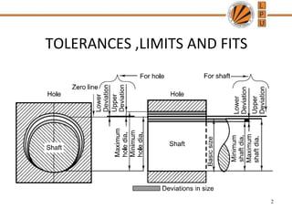
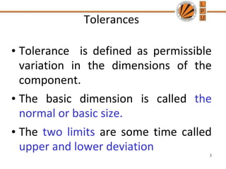
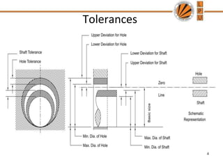
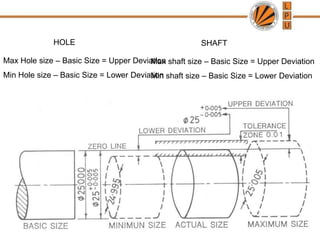
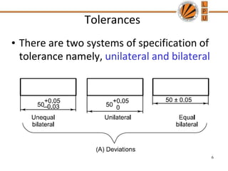
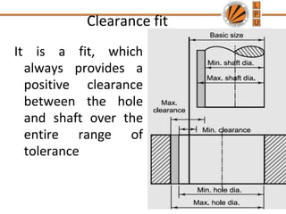
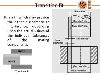
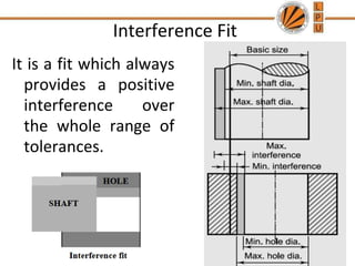
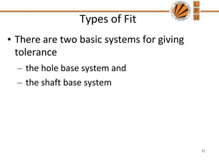
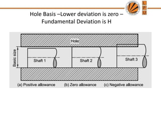
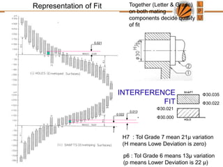
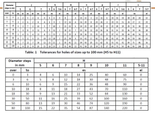
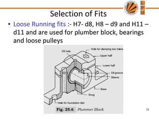
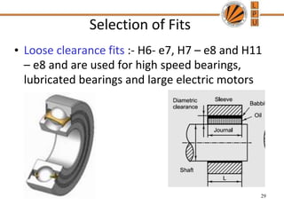
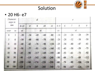
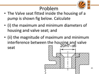
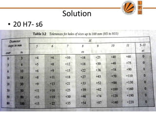
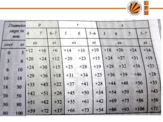
MEC223
Design of Machine Element -I
TOLERANCES ,LIMITS AND FITS
2
Tolerances
• Tolerance is defined as permissible
variation in the dimensions of the
component.
• The basic dimension is called the
normal or basic size.
• The two limits are some time called
upper and lower deviation
3
Tolerances
4
Max Hole size – Basic Size = Upper Deviation
Min Hole size – Basic Size = Lower Deviation
HOLE
Max shaft size – Basic Size = Upper Deviation
Min shaft size – Basic Size = Lower Deviation
SHAFT
Tolerances
• There are two systems of specification of
tolerance namely, unilateral and bilateral
6
Types of Fit
• When two parts are to be assembled, the
relationship resulting from the difference
between their sizes before assembly is
called a fit
• Clearance fit
• Transition fit
• Interference fit
7
Clearance fit
It is a fit, which
always provides a
positive clearance
between the hole
and shaft over the
entire range of
tolerance
8
Transition fit
It is a fit which may provide
the either a clearance or
interference, depending
upon the actual values of
the individual tolerances
of the mating
components.
9
Interference Fit
It is a fit which always
provides a positive
interference over
the whole range of
tolerances.
10
Types of Fit
• There are two basic systems for giving
tolerance
– the hole base system and
– the shaft base system
11
Hole Basis –Lower deviation is zero –
Fundamental Deviation is H
Shaft Basis- Upper deviation is zero-
Fundamental Deviation is h
14
BIS System of Fits and Tolerances
• The description of tolerance consists of two
parts – fundamental deviation and magnitude
of tolerance
15
Gives location
of tolerance
zone w.r.t zero
line indicated
by an
alphabet
Designated
by a number
, called grade
The fit is indicated by the basic size common to both
components followed by symbols for tolerance of each
component.
50H8/g7 or 50H8-g7
Es = Upper deviation
Ei= Lower Deviation
Es = Upper deviation
Ei= Lower Deviation
23
• 20 H6- e7
24
• 20 H6- e7
25
Together (Letter & Grade)
on both mating
components decide quality
of fit
H7 : Tol Grade 7 mean 21μ variation
(H means Lowe Deviation is zero)
Representation of Fit
0.021
0.022
0.013
Φ30.000
Φ30.021
Φ30.022
Φ30.035
p6 : Tol Grade 6 means 13μ variation
(p means Lower Deviation is 22 μ)
INTERFERENCE
FIT
27
Selection of Fits
• Loose Running fits :- H7- d8, H8 – d9 and H11 –
d11 and are used for plumber block, bearings
and loose pulleys
28
Selection of Fits
• Loose clearance fits :- H6- e7, H7 – e8 and H11
– e8 and are used for high speed bearings,
lubricated bearings and large electric motors
29
Selection of Fits
• Normal running fits :- H6- f6, H7 – f7 and H8 –
f8 and are used for shafts of gearboxes, small
electric motors and pumps
30
Selection of Fits
• Precision fits :- H6- g5, H7 – g6 and H8 – g7
and are used for pistons, slide valves and
bearing of accurate link mechanism
• Transition fits :- H6- j5, H7 – j6 and H8 – j7 and
are used for spigot and recess of the rigid
coupling and the composite gear blank
31
Selection of Fits
• Light Press fits :- H7- p6 or H7 – p7 results in
interference of parts which can be dismantled
easily as and when required. e.g. Fitting a
brass bush in the gear.
32
Selection of Fits
• Medium drive fits :- H6- r5 or H7 – r6 results in
interference of parts which can be dismantled
used for ferrous parts
• Permanent and semi permanent fits :- H6- s5 ,
H7 – s6 and H8 – S7 results in large
interference of parts which can be provide a
considerable gripping force. They are used in
valve seats and shaft collars.
33
Objective problems
• For a particular application, an H 7(0,25) fit has
been selected for the hole and a k 6(12,18) fit for
the shaft. The assembly shows
• A) Interference Fit
• B) Clearance Fit
• C) Transition fit
• D) Permanent fit
34
Objective problems
• On the drawing of the shaft the size is given as
the tolerance can be classified as
• A) unilateral tolerance
• B) Equal bilateral tolerance
• C) Unequal bilateral tolerance
• D) Positive tolerance.
35
Objective problems
• For following hole and shaft assembly ,the shaft
tolerance(in micron meter) is
• A) zero
• B) 40
• C) 60
• D) 20
36
Problem
• The main bearing of an engine is shown in fig
below. Calculate
• (i) the maximum and minimum diameters of
bush and crank pin; and
• (ii) the maximum and minimum clearances
between the crank pin and bush
37
Solution
• 20 H6- e7
38
Solution
• 20 H6- e7
39
Problem
• The Valve seat fitted inside the housing of a
pump is shown fig below. Calculate
• (i) the maximum and minimum diameters of
housing and valve seat; and
• (ii) the magnitude of maximum and minimum
interference between the housing and valve
seat
40
Solution
• 20 H7- s6
41
42
43
44
45

limits,fits and tolerances

  • 1.
  • 2.
  • 3.
    Tolerances • Tolerance isdefined as permissible variation in the dimensions of the component. • The basic dimension is called the normal or basic size. • The two limits are some time called upper and lower deviation 3
  • 4.
  • 5.
    Max Hole size– Basic Size = Upper Deviation Min Hole size – Basic Size = Lower Deviation HOLE Max shaft size – Basic Size = Upper Deviation Min shaft size – Basic Size = Lower Deviation SHAFT
  • 6.
    Tolerances • There aretwo systems of specification of tolerance namely, unilateral and bilateral 6
  • 7.
    Types of Fit •When two parts are to be assembled, the relationship resulting from the difference between their sizes before assembly is called a fit • Clearance fit • Transition fit • Interference fit 7
  • 8.
    Clearance fit It isa fit, which always provides a positive clearance between the hole and shaft over the entire range of tolerance 8
  • 9.
    Transition fit It isa fit which may provide the either a clearance or interference, depending upon the actual values of the individual tolerances of the mating components. 9
  • 10.
    Interference Fit It isa fit which always provides a positive interference over the whole range of tolerances. 10
  • 11.
    Types of Fit •There are two basic systems for giving tolerance – the hole base system and – the shaft base system 11
  • 12.
    Hole Basis –Lowerdeviation is zero – Fundamental Deviation is H
  • 13.
    Shaft Basis- Upperdeviation is zero- Fundamental Deviation is h
  • 14.
  • 15.
    BIS System ofFits and Tolerances • The description of tolerance consists of two parts – fundamental deviation and magnitude of tolerance 15 Gives location of tolerance zone w.r.t zero line indicated by an alphabet Designated by a number , called grade
  • 17.
    The fit isindicated by the basic size common to both components followed by symbols for tolerance of each component. 50H8/g7 or 50H8-g7
  • 19.
    Es = Upperdeviation Ei= Lower Deviation
  • 21.
    Es = Upperdeviation Ei= Lower Deviation
  • 23.
  • 24.
  • 25.
  • 26.
    Together (Letter &Grade) on both mating components decide quality of fit H7 : Tol Grade 7 mean 21μ variation (H means Lowe Deviation is zero) Representation of Fit 0.021 0.022 0.013 Φ30.000 Φ30.021 Φ30.022 Φ30.035 p6 : Tol Grade 6 means 13μ variation (p means Lower Deviation is 22 μ) INTERFERENCE FIT
  • 27.
  • 28.
    Selection of Fits •Loose Running fits :- H7- d8, H8 – d9 and H11 – d11 and are used for plumber block, bearings and loose pulleys 28
  • 29.
    Selection of Fits •Loose clearance fits :- H6- e7, H7 – e8 and H11 – e8 and are used for high speed bearings, lubricated bearings and large electric motors 29
  • 30.
    Selection of Fits •Normal running fits :- H6- f6, H7 – f7 and H8 – f8 and are used for shafts of gearboxes, small electric motors and pumps 30
  • 31.
    Selection of Fits •Precision fits :- H6- g5, H7 – g6 and H8 – g7 and are used for pistons, slide valves and bearing of accurate link mechanism • Transition fits :- H6- j5, H7 – j6 and H8 – j7 and are used for spigot and recess of the rigid coupling and the composite gear blank 31
  • 32.
    Selection of Fits •Light Press fits :- H7- p6 or H7 – p7 results in interference of parts which can be dismantled easily as and when required. e.g. Fitting a brass bush in the gear. 32
  • 33.
    Selection of Fits •Medium drive fits :- H6- r5 or H7 – r6 results in interference of parts which can be dismantled used for ferrous parts • Permanent and semi permanent fits :- H6- s5 , H7 – s6 and H8 – S7 results in large interference of parts which can be provide a considerable gripping force. They are used in valve seats and shaft collars. 33
  • 34.
    Objective problems • Fora particular application, an H 7(0,25) fit has been selected for the hole and a k 6(12,18) fit for the shaft. The assembly shows • A) Interference Fit • B) Clearance Fit • C) Transition fit • D) Permanent fit 34
  • 35.
    Objective problems • Onthe drawing of the shaft the size is given as the tolerance can be classified as • A) unilateral tolerance • B) Equal bilateral tolerance • C) Unequal bilateral tolerance • D) Positive tolerance. 35
  • 36.
    Objective problems • Forfollowing hole and shaft assembly ,the shaft tolerance(in micron meter) is • A) zero • B) 40 • C) 60 • D) 20 36
  • 37.
    Problem • The mainbearing of an engine is shown in fig below. Calculate • (i) the maximum and minimum diameters of bush and crank pin; and • (ii) the maximum and minimum clearances between the crank pin and bush 37
  • 38.
  • 39.
  • 40.
    Problem • The Valveseat fitted inside the housing of a pump is shown fig below. Calculate • (i) the maximum and minimum diameters of housing and valve seat; and • (ii) the magnitude of maximum and minimum interference between the housing and valve seat 40
  • 41.
  • 42.
  • 43.
  • 44.
  • 45.