This document discusses various thermodynamic power cycles used in internal combustion engines. It describes air standard cycles which approximate actual engine cycles using assumptions like ideal gas behavior and reversible processes. The key cycles covered are:
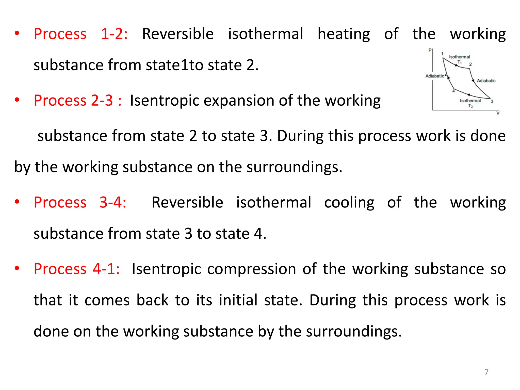
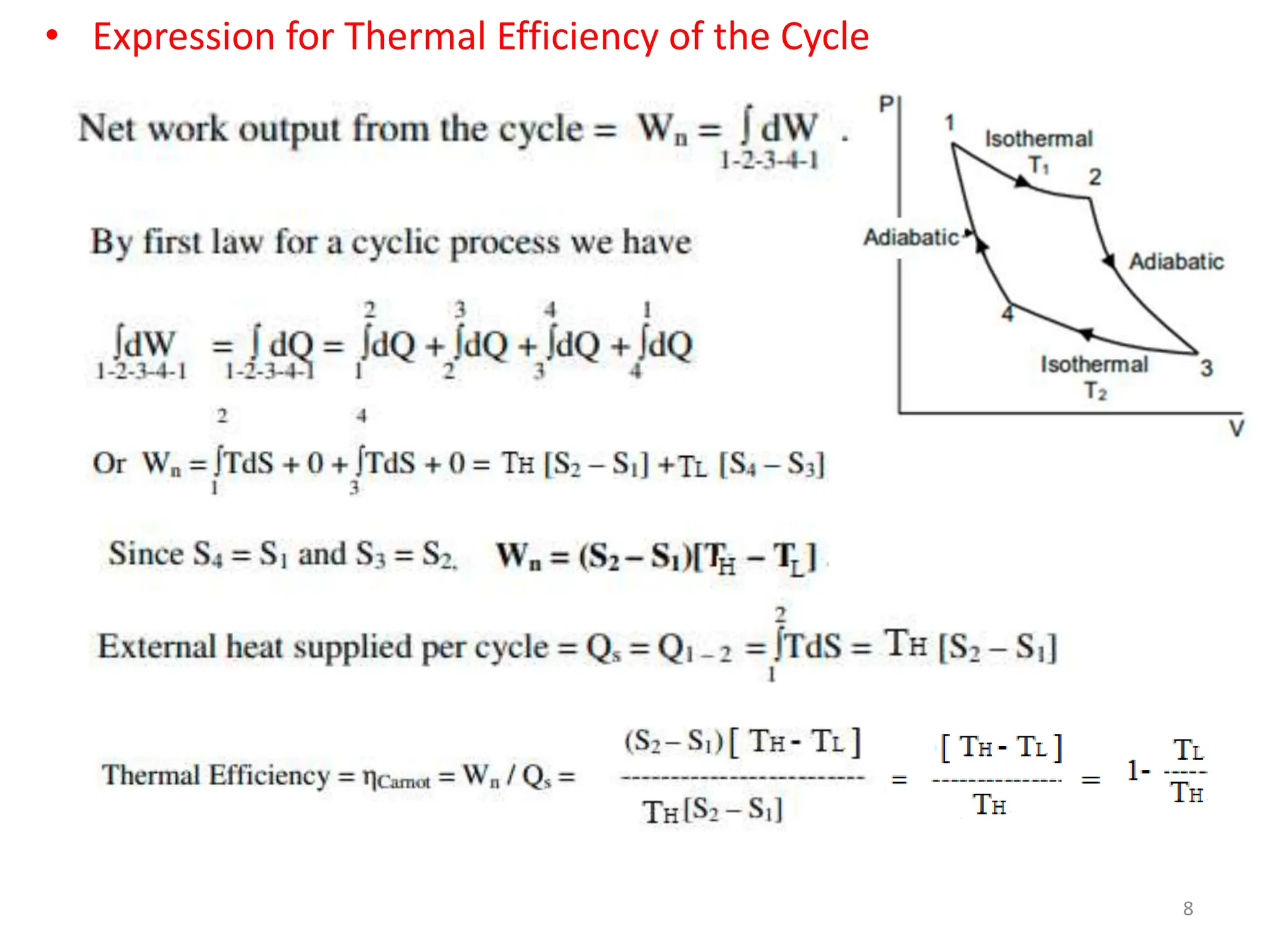
- Carnot cycle, the most efficient theoretical cycle but impractical to implement.
- Otto cycle for spark ignition engines, with efficiency increasing with compression ratio.
- Diesel cycle for compression ignition engines, allowing higher compression ratios and efficiencies than Otto cycle.
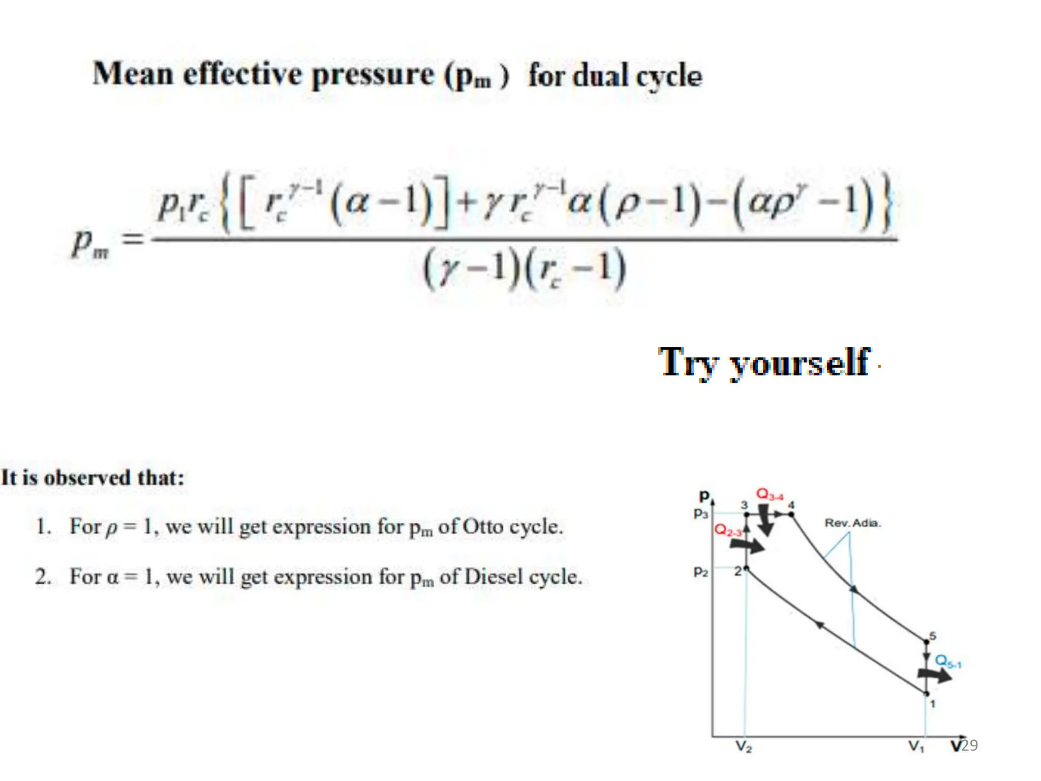
- Dual combustion cycle as a better approximation for modern diesel engines where combustion occurs in two stages.
The document analyzes each cycle thermodynamically and compares the efficiencies of Otto, Diesel and Dual cycles at