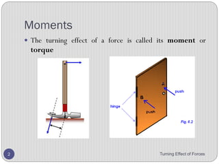
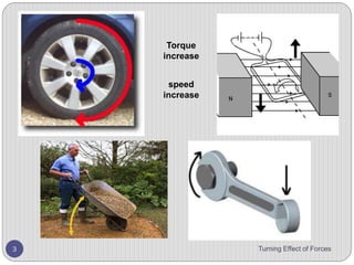
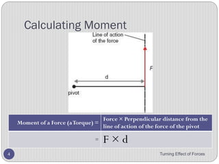
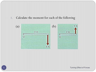
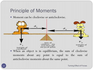
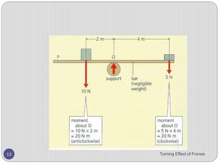
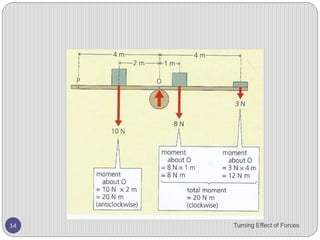
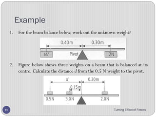
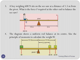
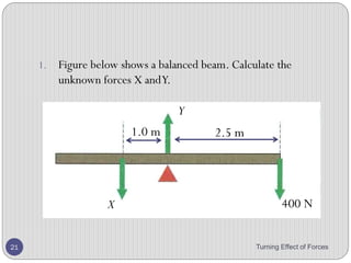
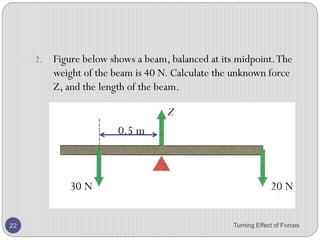
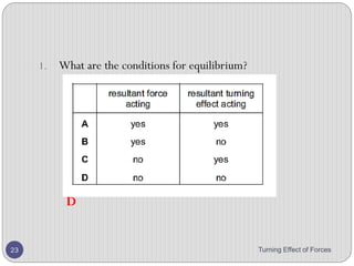
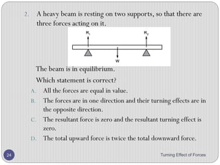
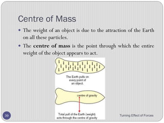
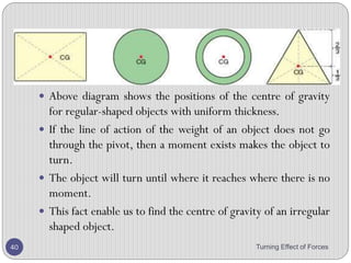
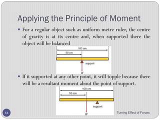
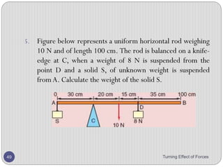
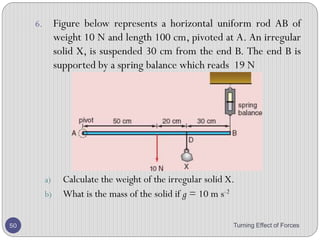
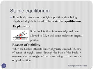
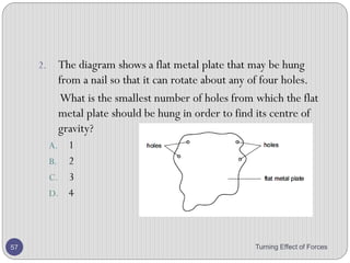
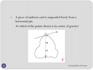
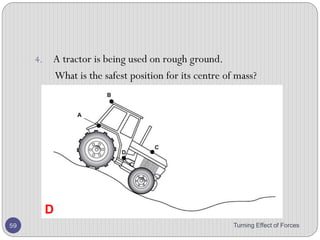
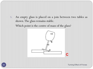
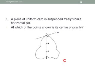
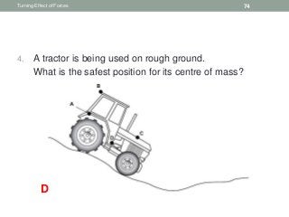
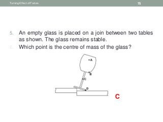
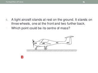
1. The document discusses moments, which describe the turning effect of forces. A moment is calculated by multiplying the force by the perpendicular distance from the pivot.
2. It provides examples of calculating moments and using the principle of moments, which states that for an object in equilibrium, the sum of clockwise moments equals the sum of anticlockwise moments.
3. Determining the center of mass of an object allows it to be balanced on a pivot. The center of mass can be found experimentally by balancing irregular objects on different points and identifying where the lines intersect.
This is a summary of the topic "Energy, work and power" in the GCE O levels subject: Physics. Students taking either the combined science (chemistry/physics) or pure Physics will find this useful. These slides are prepared according to the learning outcomes required by the examinations board.
This slide show accompanies the learner guide "Mechanical Technology Grade 10" by Charles Goodwin, Andre Lategan & Daniel Meyer, published by Future Managers Pty Ltd. For more information visit our website www.futuremanagers.net
Physics 161Static Equilibrium and Rotational Balance Intro.docxrandymartin91030
Physics 161
Static Equilibrium and Rotational Balance
Introduction
In Part I of this lab, you will observe static equilibrium for a meter stick suspended horizontally. In Part II, you will observe the rotational balance of a cylinder on an incline. You will vary the mass hanging from the side of the cylinder for different angles.
Reference
Young and Freedman, University Physics, 12th Edition: Chapter 11, section 3
Theory
Part I: When forces act on an extended body, rotations about axes on the body can result as well as translational motion from unbalanced forces. Static equilibrium occurs when the net force and the net torque are both equal to zero. We will examine a special case where forces are only acting in the vertical direction and can therefore be summed simply without breaking them into components:
(1)
Torques may be calculated about the axis of your choosing:
(2)
where torque is specified by the equation:
(3)
where d is the lever arm (or moment arm) for the force. The lever arm is the perpendicular distance from the line of force to the axis about which you are calculating the torque.
Normally, up is "+" and down is "-" for forces. For torques, it is convenient to define clockwise as "-" and counterclockwise as "+". Whatever you decide to do, be consistent with your signs and make sure you understand what a "+" or "-" value for your force or torque means directionally.
Part II: Any round object when placed on an incline has tendency of rotating towards the bottom of an incline. If the downward force that causes the object to accelerate down the slope is canceled by another force, the object will remain stationary on the incline. Figure 1 shows the configuration of the setup. In order to have the rubber cylinder in static equilibrium we should satisfy the following conditions:
(4)
Figure 1: Experimental setup for Part II
The condition that the net force along the x-axis (which is conveniently taken along the incline) must be zero yields the relationship. (Prove this!)
Without static friction the cylinder would slide down the incline; the presence of friction causes a torque in clockwise (negative) direction. In order to have static equilibrium we need to balance that torque with a torque in counterclockwise direction. This is achieved by hanging the appropriate mass m.
Applying the last condition to the center of the cylinder will result in:
where r, the radius of the small cylinder (PVC fitting), is the moment arm for the mass m and R, the radius of the rubber cylinder, is the moment arm for the frictional force which accounts for M and m. Combining this equation with the equation for Ffr from above will result in:
(5)
(6)
By adjusting the mass m, we can observe how the equilibrium can be achieved.
Procedure
Part I: Static Equilibrium
Figure 2: Diagram of Torque Experiment Setup
1. Weigh the meter stick you use, including the metal hangers.
2. Attach .
Detection of Radioactivity
Characteristics of the Three Types of Emission
Nuclear Reactions
Half-Life
Uses of Radioactive Isotopes Including Safety Precautions
Synthetic Fiber Construction in lab .pptxPavel ( NSTU)
Synthetic fiber production is a fascinating and complex field that blends chemistry, engineering, and environmental science. By understanding these aspects, students can gain a comprehensive view of synthetic fiber production, its impact on society and the environment, and the potential for future innovations. Synthetic fibers play a crucial role in modern society, impacting various aspects of daily life, industry, and the environment. ynthetic fibers are integral to modern life, offering a range of benefits from cost-effectiveness and versatility to innovative applications and performance characteristics. While they pose environmental challenges, ongoing research and development aim to create more sustainable and eco-friendly alternatives. Understanding the importance of synthetic fibers helps in appreciating their role in the economy, industry, and daily life, while also emphasizing the need for sustainable practices and innovation.
This is a presentation by Dada Robert in a Your Skill Boost masterclass organised by the Excellence Foundation for South Sudan (EFSS) on Saturday, the 25th and Sunday, the 26th of May 2024.
He discussed the concept of quality improvement, emphasizing its applicability to various aspects of life, including personal, project, and program improvements. He defined quality as doing the right thing at the right time in the right way to achieve the best possible results and discussed the concept of the "gap" between what we know and what we do, and how this gap represents the areas we need to improve. He explained the scientific approach to quality improvement, which involves systematic performance analysis, testing and learning, and implementing change ideas. He also highlighted the importance of client focus and a team approach to quality improvement.
Unit 8 - Information and Communication Technology (Paper I).pdfThiyagu K
This slides describes the basic concepts of ICT, basics of Email, Emerging Technology and Digital Initiatives in Education. This presentations aligns with the UGC Paper I syllabus.
The Art Pastor's Guide to Sabbath | Steve ThomasonSteve Thomason
What is the purpose of the Sabbath Law in the Torah. It is interesting to compare how the context of the law shifts from Exodus to Deuteronomy. Who gets to rest, and why?
Palestine last event orientationfvgnh .pptxRaedMohamed3
An EFL lesson about the current events in Palestine. It is intended to be for intermediate students who wish to increase their listening skills through a short lesson in power point.
Welcome to TechSoup New Member Orientation and Q&A (May 2024).pdfTechSoup
In this webinar you will learn how your organization can access TechSoup's wide variety of product discount and donation programs. From hardware to software, we'll give you a tour of the tools available to help your nonprofit with productivity, collaboration, financial management, donor tracking, security, and more.
The Roman Empire A Historical Colossus.pdfkaushalkr1407
The Roman Empire, a vast and enduring power, stands as one of history's most remarkable civilizations, leaving an indelible imprint on the world. It emerged from the Roman Republic, transitioning into an imperial powerhouse under the leadership of Augustus Caesar in 27 BCE. This transformation marked the beginning of an era defined by unprecedented territorial expansion, architectural marvels, and profound cultural influence.
The empire's roots lie in the city of Rome, founded, according to legend, by Romulus in 753 BCE. Over centuries, Rome evolved from a small settlement to a formidable republic, characterized by a complex political system with elected officials and checks on power. However, internal strife, class conflicts, and military ambitions paved the way for the end of the Republic. Julius Caesar’s dictatorship and subsequent assassination in 44 BCE created a power vacuum, leading to a civil war. Octavian, later Augustus, emerged victorious, heralding the Roman Empire’s birth.
Under Augustus, the empire experienced the Pax Romana, a 200-year period of relative peace and stability. Augustus reformed the military, established efficient administrative systems, and initiated grand construction projects. The empire's borders expanded, encompassing territories from Britain to Egypt and from Spain to the Euphrates. Roman legions, renowned for their discipline and engineering prowess, secured and maintained these vast territories, building roads, fortifications, and cities that facilitated control and integration.
The Roman Empire’s society was hierarchical, with a rigid class system. At the top were the patricians, wealthy elites who held significant political power. Below them were the plebeians, free citizens with limited political influence, and the vast numbers of slaves who formed the backbone of the economy. The family unit was central, governed by the paterfamilias, the male head who held absolute authority.
Culturally, the Romans were eclectic, absorbing and adapting elements from the civilizations they encountered, particularly the Greeks. Roman art, literature, and philosophy reflected this synthesis, creating a rich cultural tapestry. Latin, the Roman language, became the lingua franca of the Western world, influencing numerous modern languages.
Roman architecture and engineering achievements were monumental. They perfected the arch, vault, and dome, constructing enduring structures like the Colosseum, Pantheon, and aqueducts. These engineering marvels not only showcased Roman ingenuity but also served practical purposes, from public entertainment to water supply.
Read| The latest issue of The Challenger is here! We are thrilled to announce that our school paper has qualified for the NATIONAL SCHOOLS PRESS CONFERENCE (NSPC) 2024. Thank you for your unwavering support and trust. Dive into the stories that made us stand out!
The Indian economy is classified into different sectors to simplify the analysis and understanding of economic activities. For Class 10, it's essential to grasp the sectors of the Indian economy, understand their characteristics, and recognize their importance. This guide will provide detailed notes on the Sectors of the Indian Economy Class 10, using specific long-tail keywords to enhance comprehension.
For more information, visit-www.vavaclasses.com
5. Moment factor
• The moment of a force is bigger if the force is bigger.
• The moment of a force is bigger if it acts further from the
pivot.
• The moment of force is greatest if it acts at 90ᵒ to the
object it acts on
Turning Effect of Forces 5
6. Moments
• Make calculations using moment of a force = force x
perpendicular distance from the pivot and the principle of
moments.
• .
Turning Effect of Forces 6
7. Calculating Moment
Turning Effect of Forces 7
Moment of a Force =
Force × Perpendicular distance from the line
of action of the force to the pivot
= F × d
9. 2. A mechanic uses a 15 cm long spanner and applies a
force of 300 N at the end of the spanner to undo a nut.
What is the moment he applies?
3. The radius of the wheel of fortune is 1.2 m, and the
operator applies a force of 45 N tangentially to get it
spinning. What torque has he supplied?
4. A 32 kg child sits on a seesaw. If she is 2.2 m from the
pivot, what is the moment that her weight exerts?
5. A force of 40 N is acting at the end of a beam. If the
distance of this force from the pivot is 2.0 m, what is the
moment by this force?
Turning Effect of Forces 9
10. 6. Figure below shows three positions of the pedal on a
bicycle which has a crank 0.20 m long. If the cyclist
exerts the same vertically downward push of 25 N with
his foot, in which case A, B and C, is the turning effect
i. 0,
ii. between 0 and 5 Nm,
iii. 25 0.2 = 5 Nm?
Turning Effect of Forces 10
11. 1. If a nut and bolt are difficult to undo, it may be easier to
turn the nut by using a longer spanner.
This is because the longer spanner gives
A. a larger turning moment.
B. a smaller turning moment.
C. less friction.
D. more friction.
Turning Effect of Forces 11
12. 2. A horizontal pole is attached to the side of a building.
There is a pivot P at the wall and a chain is connected
from the end of the pole to a point higher up the wall.
There is a tension force F in the chain.
What is the moment of the force F about the pivot P?
A. F x d
B. F x h
C. F x l
D. F x s
Turning Effect of Forces 12
13. 3. A plane lamina is freely suspended from point P.
4. The weight of the lamina is 2.0 N and the centre of
mass is at C.
5. The lamina is displaced to the position shown. What is
the moment that will cause the lamina to swing?
A. 0.60 N m clockwise
B. 0.80 N m anticlockwise
C. 1.0 N m clockwise
D. 1.0 N m anticlockwise
Turning Effect of Forces 13
14. Moments
• State the principle of moments for a body in equilibrium.
Turning Effect of Forces 14
15. Balance Beam
• Two forces are causing this see-saw to tip.
• The girl’s weight causes it to tip to the left, while her father
provides a force to tip it to the right.
• He can increase the turning effect of his force by increasing
the force, or by pushing down at a greater distance from the
pivot.
Turning Effect of Forces 15
weight of girl
father’s
push
16. Principle of Moments
• Moment can be clockwise or anticlockwise.
• When an object is in equilibrium, the sum of clockwise
moments about any point is equal to the sum of
anticlockwise moments about the same point.
Turning Effect of Forces 16
19. Example
Turning Effect of Forces 19
1. For the beam balance below, work out the unknown
weight?
2. Figure below shows three weights on a beam that is
balanced at its centre. Calculate the distance d from the
0.5 N weight to the pivot.
20. Turning Effect of Forces 20
4. The diagram shows a uniform rod balance at its centre.
Use the principle of moments to calculate the weight W.
3. A boy weighing 600 N sits on the see-saw at a distance
of 1.5 m from the pivot. What is the force F required at
the other end to balance the see-saw?
21. 5. Figure below, someone is trying to balance a plank with
stones. The plank has negligible weight.
Turning Effect of Forces 21
22. a. Calculate the moment of the 4 N force about O.
b. Calculate the moment of the 6 N force about O.
c. Will the plank balance? If not which way will it tip?
d. What extra force is needed at point P to balance the plank?
e. In which direction must the force at P act?
Turning Effect of Forces 22
23. Turning Effect of Forces 23
6. The board shown is hinged at A and supported by a
vertical rope at B, 3.0 m from A. A boy weighing 600 N
stands at the end D of the board, which is 4.0 m from
the hinge. Neglecting the weight of the board, calculate
the force F on the rope.
24. Conditions for equilibrium
• If an object is in equilibrium, the forces on it must balance
as well as their turning effect.
• So:
• The sum of the forces in one direction must equal to the sum of the
forces in the opposite direction.
• The principle of moments must apply.
Turning Effect of Forces 24
25. 1. Figure below shows a balanced beam. Calculate the
unknown forces X and Y.
Turning Effect of Forces 25
Y
X 400 N
2.5 m1.0 m
26. 2. Figure below shows a beam, balanced at its midpoint.
The weight of the beam is 40 N. Calculate the unknown
force Z, and the length of the beam.
Turning Effect of Forces 26
30 N
Z
0.5 m
20 N
27. 3. Figure below shows a balanced beam. Calculate the
unknown forces X and Y.
Turning Effect of Forces 27
Y
X600 N
29. Experiment
• Aim: To verify the principle of moments
• Apparatus:
1. Retort stand
2. Metre rule with drill hole at the 50 cm mark.
3. Pivot
4. 10 g slotted mass with hanger labelled W1
5. 100 g slotted mass with hanger labelled W2
Turning Effect of Forces 29
31. • Procedure:
2. Suspend different weights, W1 and W2 at different distances d1
and d2 from the pivot.
3. Carefully adjust the distances d1 and d2 until the rule balances
horizontally.
4. Record the values of W1,W2,d1 and d2.
5. Repeat procedure 2, 3 and 4 for different values of W1,W2,d1 and
d2.
Turning Effect of Forces 31
32. • Results
• For each set of results, calculate (W1 × d1) and (W2 × d2).
• Conclusion
• For each set of readings, within the limits of experimental accuracy, (W1 ×
d1) and (W2 × d2) will be equal for each set of readings.
• Hence clockwise moment equal anticlockwise moment.
Turning Effect of Forces 32
33. 1. What are the conditions for equilibrium?
Turning Effect of Forces 33
D
34. 2. A heavy beam is resting on two supports, so that there are
three forces acting on it.
The beam is in equilibrium.
Which statement is correct?
A. All the forces are equal in value.
B. The forces are in one direction and their turning effects are in the
opposite direction.
C. The resultant force is zero and the resultant turning effect is zero.
D. The total upward force is twice the total downward force.
Turning Effect of Forces 34
35. 3. Two blocks are placed on a beam which balances on a
pivot at its centre. The weight of the beam is negligible.
Turning Effect of Forces 35
36. 1. Which diagram shows the forces acting on the beam?
2. (The length of each arrow represents the size of a
force.)
Turning Effect of Forces 36
B
37. 4. The weights of four objects, 1 to 4, are compared using
a balance.
Which object is the lightest?
A. object 1
B. object 2
C. object 3
D. object 4
Turning Effect of Forces 37
38. 5. Three children, X, Y and Z, are using a see-saw to
compare their weights.
6. Which line in the table shows the correct order of the
children’s weights?
Turning Effect of Forces 38
C
39. 6. Two equal forces F act on each of four planks.
Which plank turns?
Turning Effect of Forces 39
D
40. 7. The diagrams show a uniform rod with its midpoint on a
pivot.
8. Two equal forces F are applied to the rod, as shown.
9. Which diagram shows the rod in equilibrium?
Turning Effect of Forces 40
C
41. 8. Forces are applied to a uniform beam pivoted at its
centre.
9. Which beam is balanced?
Turning Effect of Forces 41
D
42. 9. The diagram shows a uniform half-metre rule balanced
at its mid-point.
1. What is the weight of the metal block?
A. 50 N
B. 75 N
C. 100 N
D. 150 N
Turning Effect of Forces 42
43. 10. The diagram shows a boy of weight 500 N sitting on a
see-saw. He sits 2.0 m from the pivot.
1. What is the force F needed to balance the see-saw?
Turning Effect of Forces 43
A 250 N B 750 N C 1000 N D 3000 N A
44. 11. A beam is pivoted at its centre. Two masses are
suspended at equal distances from the pivot as shown
in the diagram.
Which statement is correct?
A. If X has a mass of exactly 2 kg, it will rise.
B. If X has a mass of less than 2 kg, it will fall.
C. If X has a mass of more than 2 kg, it will fall.
D. If X has a mass of more than 2 kg, it will rise.
Turning Effect of Forces 44
45. 12. In an experiment, five identical bags of rice are balanced
by a 10 kg mass.
Two bags of rice are added to the other five.
What mass will now balance the bags?
A. 3.5 kg
B. 7.0 kg
C. 10 kg
D. 14 kg
Turning Effect of Forces 45
46. 13. In an experiment, six identical bags of flour are balanced
by a 9 kg mass.
14. Two bags of flour are removed. What mass will balance
the remaining bags?
A. 3 kg
B. 6 kg
C. 7 kg
D. 9 kg
Turning Effect of Forces 46
47. 14. A simple balance has two pans suspended from the ends of
arms of equal length. When it is balanced, the pointer is at 0.
15. Four masses (in total) are placed on the pans, with one or more
on pan X and the rest on pan Y.
16. Which combination of masses can be used to balance the
pans?
A. 1 g, 1 g, 5 g, 10 g
B. 1 g, 2 g, 2 g, 5 g
C. 2 g, 5 g, 5 g, 10 g
D. 2 g, 5 g, 10 g, 10 g
Turning Effect of Forces 47
48. 15. A load is to be moved using a wheelbarrow. The total mass of
the load and wheelbarrow is 60 kg.
The gravitational field strength is 10 N / kg.
What is the size of force F needed just to lift the loaded
wheelbarrow?
A. 350 N
B. 430 N
C. 600 N
D. 840 N
Turning Effect of Forces 48
49. 16. The diagram shows a wheelbarrow and its load, which
have a total weight of 150 N. This is supported by a
vertical force F at the ends of the handles.
What is the value of F?
A. 75 N
B. 150 N
C. 225 N
D. 300 N
Turning Effect of Forces 49
50. 17. A driver’s foot presses with a steady force of 20 N on a
pedal in a car as shown.
What is the force F pulling on the piston?
A. 2.5 N
B. 10 N
C. 100 N
D. 160 N
Turning Effect of Forces 50
51. Centre of mass
• Describe how to determine the position of the centre of
mass of a plane lamina.
Turning Effect of Forces 51
52. Centre of Mass
• The weight of an object is due to the attraction of the
Earth on all these particles.
• The centre of mass is the point through which the entire
weight of the object appears to act.
Turning Effect of Forces 52
53. • Above diagram shows the positions of the centre of
gravity for regular-shaped objects with uniform
thickness.
• If the line of action of the weight of an object does not
go through the pivot, then a moment exists makes the
object to turn.
• The object will turn until where it reaches where there
is no moment.
• This fact enable us to find the centre of gravity of an
irregular shaped object.
Turning Effect of Forces 53
54. Experiment
• Aim: To determine the centre of mass of a plane lamina
• Apparatus:
• Retort stand
• Cork
• Plumb line
• Lamina
Turning Effect of Forces 54
55. • Procedure:
• On the lamina, make three holes near the edge of the lamina.
• Suspend the lamina through one of the holes.
• Hang the plumb line on the pin.
• When the plumb line is steady, make a dot on the position of the
line at the edge of the lamina
• Repeat steps 2-4 for the other two holes
• Conclusion
• The point where the lines meet is the centre of mass of the body.
Turning Effect of Forces 55
57. Applying the Principle of Moment
• For a regular object such as uniform metre ruler, the
centre of gravity is at its centre and, when supported there
the object will be balanced
• If it supported at any other point, it will topple because
there will be a resultant moment about the point of
support.
Turning Effect of Forces 57
58. Example
1. The illustration in figure below represents a metre scale
balancing on a knife edge at 20 cm mark when a weight
of 60 N is suspended from 10 cm mark. Calculate the
weight of the ruler.
Turning Effect of Forces 58
59. 2. Figure below shows a uniform metre rule weighing 30 N
pivoted on a wedge placed under the 40 cm mark and
carrying a weight of 70 N hanging from the 10 cm mark.
The ruler is balanced horizontally by a weight W
hanging from the 100 cm mark. Calculate the value of
the weight W.
Turning Effect of Forces 59
60. 3. Figure below shows a uniform metre rule pivoted off-
centre but maintained in equilibrium by a suspended
weight of 2.4 N. The weight is hung 5 cm from one end
of the metre rule. What is the weight of the metre rule?
Turning Effect of Forces 60
61. 4. Figure below shows a uniform metre rule weighing 3.0
N pivoted on a wedge placed under the 40 cm mark
and carrying a weight of 7.0 N hanging from the 10 cm
mark. The rule is kept horizontally by a weight W
hanging from the 100 cm end. Calculate the value of
the weight W.
Turning Effect of Forces 61
62. 5. Figure below represents a uniform horizontal rod
weighing 10 N and of length 100 cm. The rod is
balanced on a knife-edge at C, when a weight of 8 N is
suspended from the point D and a solid S, of unknown
weight is suspended from A. Calculate the weight of the
solid S.
Turning Effect of Forces 62
63. 6. The beam shown below is 2.0 m long and has a weight
of 20 N. It is pivoted as shown. A force of 10 N acts at
one end. What force F must be applied downwards at
the other end to balance the beam?
Turning Effect of Forces 63
64. 7. Figure below represents a horizontal uniform rod AB of
weight 10 N and length 100 cm, pivoted at A. An irregular
solid X, is suspended 30 cm from the end B. The end B
is supported by a spring balance which reads 19 N
a) Calculate the weight of the irregular solid X.
b) What is the mass of the solid if g = 10 m s-2
Turning Effect of Forces 64
65. Stability
• Describe qualitatively the effect of the position of the
centre of mass on the stability of simple objects.
Turning Effect of Forces 65
66. Stability
• Stability is the measure of a body’s ability to maintain its
original position.
• The degree of stability in an object's position depends on
how must its center of gravity will be changed if it is
moved.
• There are three states of equilibrium:
• Stable equilibrium
• Unstable equilibrium
• Neutral equilibrium
Turning Effect of Forces 66
67. Stable equilibrium
• If the body returns to its original position after being
displaced slightly it is said to be in stable equilibrium.
Turning Effect of Forces 67
If the book is lifted from one edge and
then allowed to fall, it will come back to
its original position.
Explanation
Reason of stability
When the book is lifted its center of gravity is
raised. The line of action of weight passes through
the base of the book. A moment due to weight of
the book brings it back to the original position.
68. Unstable equilibrium
• If the body continues to move away from its original
position after being displaced, it is said to be in unstable
equilibrium.
Turning Effect of Forces 68
Explanation
If thin rod standing vertically is slightly
disturbed from its position it will not come
back to its original position.
Reason of instability
When the rod is slightly disturbed its center of
gravity is lowered . The line of action of its
weight lies outside the base of rod. The
moment due to weight of the rod toppled it
down.
69. Neutral equilibrium
• If an object remains wherever it is after being displaced, it
is said to be in neutral equilibrium.
Turning Effect of Forces 69
Explanation
If a ball is pushed slightly to roll, it
will neither come back to its
original nor it will roll forward rather
it will remain at rest.
Reason of neutral equilibrium
If the ball is rolled, its center of gravity is neither
raised nor lowered. This means that its center of
gravity is at the same height as before.
70. Designing for Stability
• There are two ways to make a body more stable.
1. Lowering its centre of gravity;
2. Increasing the area of its base.
Turning Effect of Forces 70
71. 1. A piece of card has its centre of mass at M.
2. Which diagram shows how it hangs when suspended
by a thread?
Turning Effect of Forces 71
A
72. 2. The diagram shows a flat metal plate that may be hung
from a nail so that it can rotate about any of four holes.
3. What is the smallest number of holes from which the
flat metal plate should be hung in order to find its centre
of gravity?
A. 1
B. 2
C. 3
D. 4
Turning Effect of Forces 72
73. 3. A piece of uniform card is suspended freely from a
horizontal pin.
4. At which of the points shown is its centre of gravity?
Turning Effect of Forces 73
C
74. 4. A tractor is being used on rough ground.
5. What is the safest position for its centre of mass?
Turning Effect of Forces 74
D
75. 5. An empty glass is placed on a join between two tables
as shown. The glass remains stable.
6. Which point is the centre of mass of the glass?
Turning Effect of Forces 75
C
76. 6. A light aircraft stands at rest on the ground. It stands on
three wheels, one at the front and two further back.
7. Which point could be its centre of mass?
Turning Effect of Forces 76
B
77. 7. The diagram shows sections of four objects of equal
mass. The position of the centre of mass of each object
has been marked with a cross.
8. Which object is the most stable?
Turning Effect of Forces 77
A
78. 8. A student uses a stand and clamp to hold a flask of
liquid.
9. Which diagram shows the most stable arrangement?
Turning Effect of Forces 78
B
79. 9. Some containers are made from thin glass.
10. Which empty container is the most stable?
Turning Effect of Forces 79
A
80. 10. The diagrams show the cross-sections of different
glasses.
11. Which one is the least stable when filled with a liquid?
Turning Effect of Forces 80
B
81. 11. The diagram shows four models of buses placed on different
ramps.
How many of these models will fall over?
A. 1
B. 2
C. 3
D. 4
Turning Effect of Forces 81
82. 12. The diagram shows four objects standing on a flat
surface.
13. The centre of mass of each object is marked M.
14. Which object will fall over?
Turning Effect of Forces 82
C
83. 13. A girl uses paper-clips to balance a
toy bird on her finger as shown.
What is the effect of the paper-
clips?
A. They help to raise the centre of mass
above her finger.
B. They help to raise the centre of mass to
her finger.
C. They help to lower the centre of mass
below her finger.
D. They do not affect the centre of mass but
increase the weight.
Turning Effect of Forces 83
84. 14. The stability of a bus is tested by tilting it on a ramp.
The diagram shows a bus that is just about to topple
over.
15. Where is the centre of mass of the bus?
Turning Effect of Forces 84
C
85. 15. Passengers are not allowed to stand on the upper deck
of double-decker buses.
Turning Effect of Forces 85
86. 1. Why is this?
A. They would cause the bus to become unstable.
B. They would cause the bus to slow down.
C. They would increase the kinetic energy of the bus.
D. They would lower the centre of mass of the bus.
Turning Effect of Forces 86