The document discusses concepts related to optics, including:
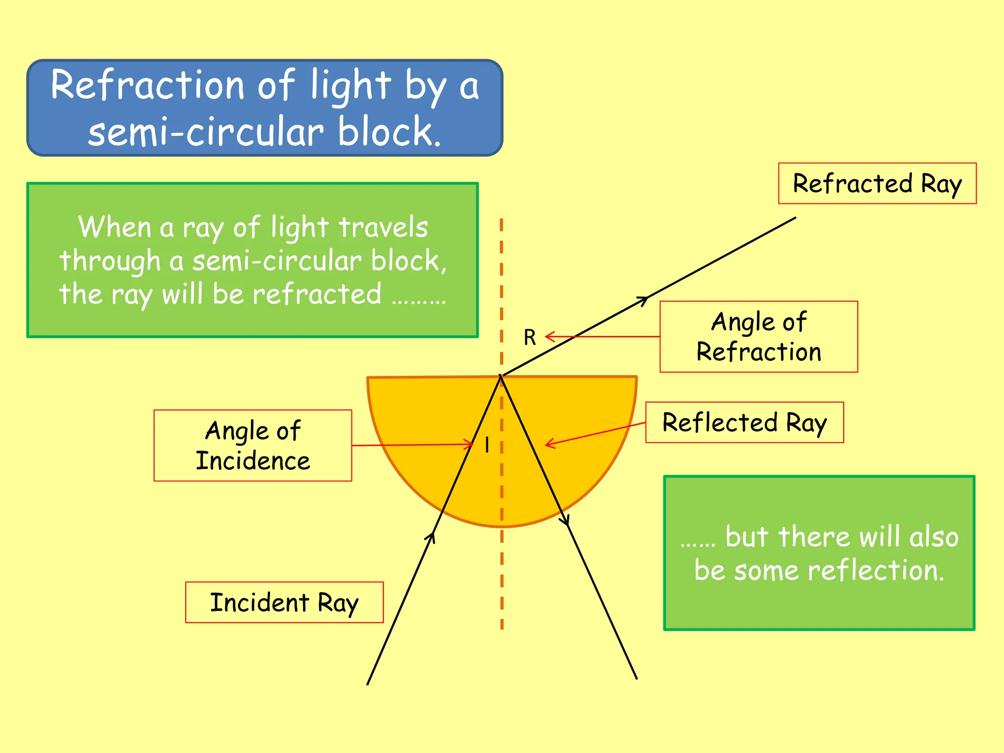
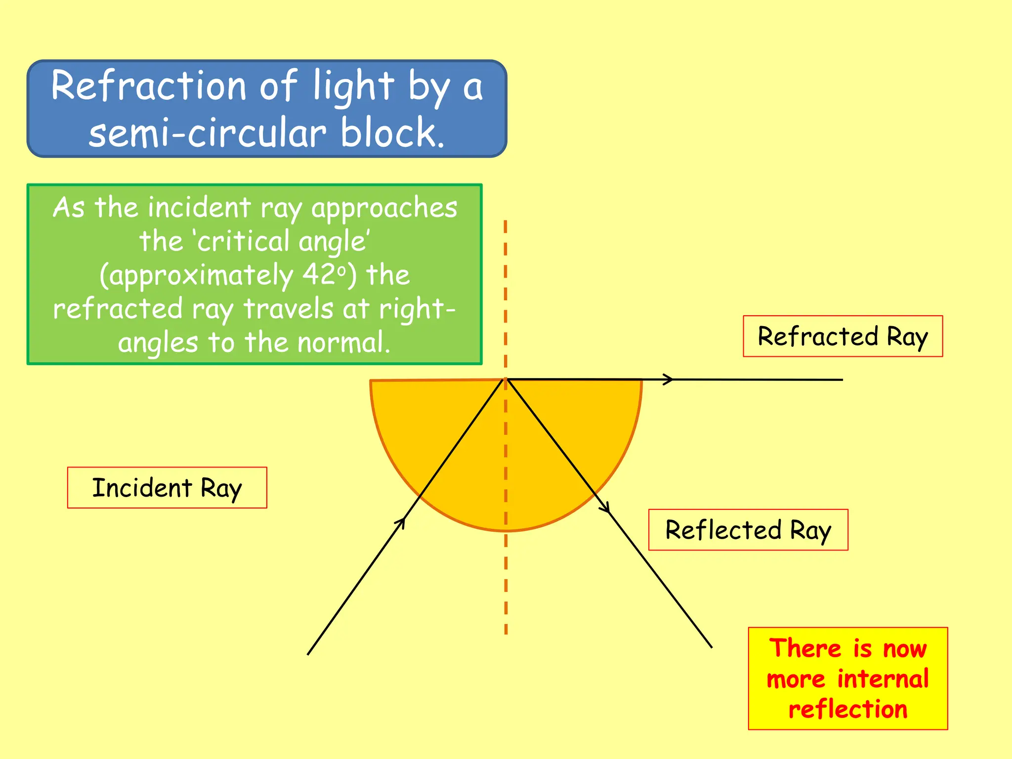
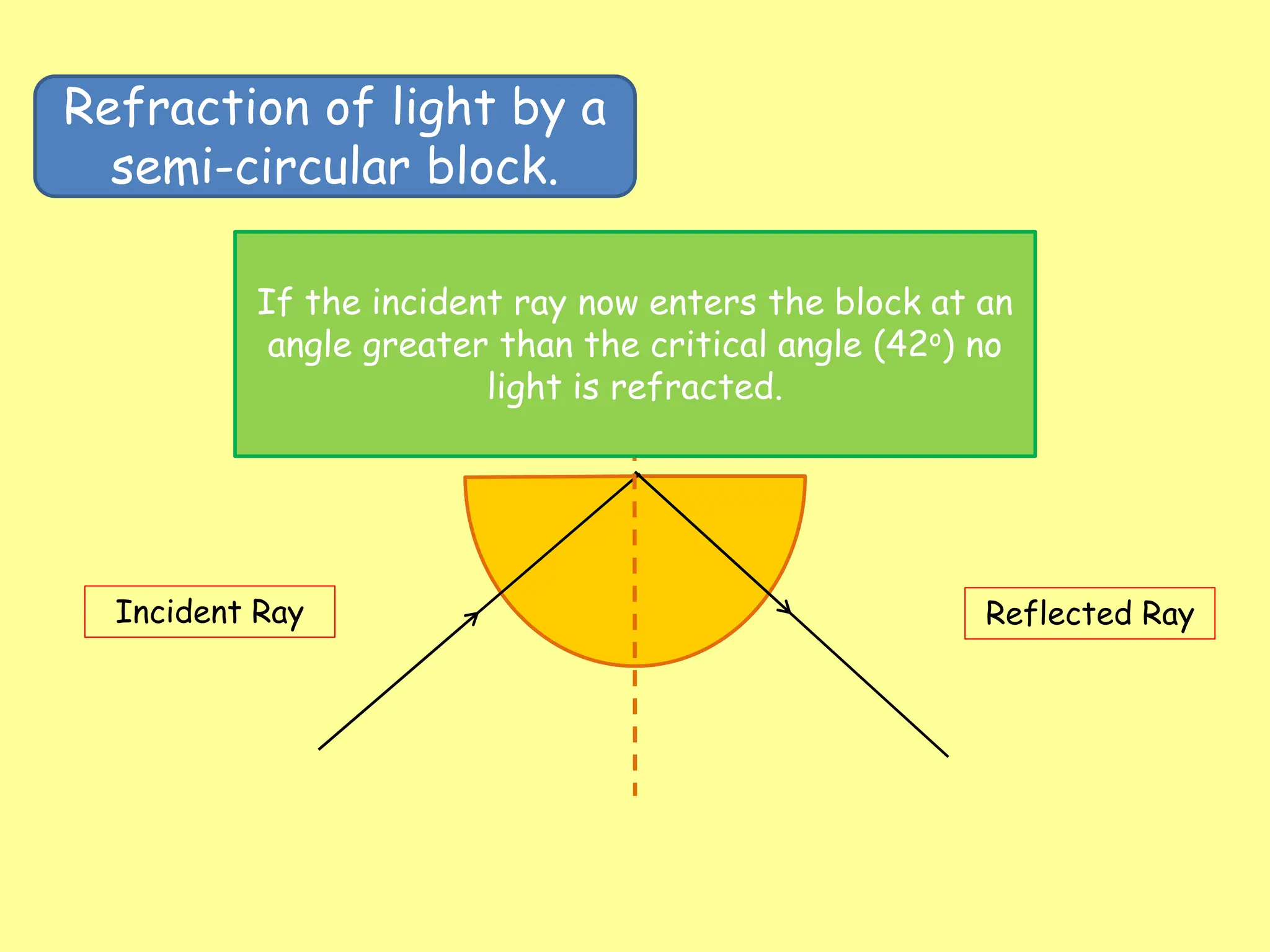
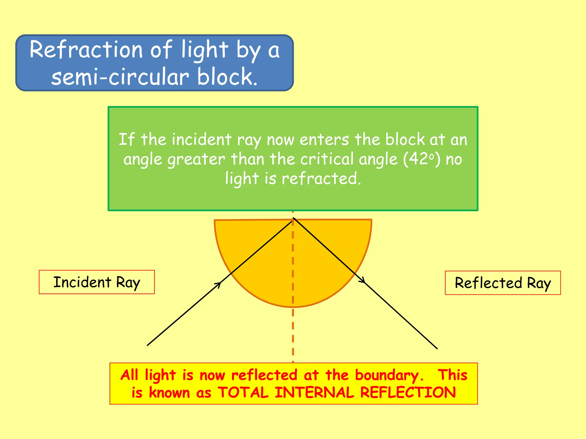
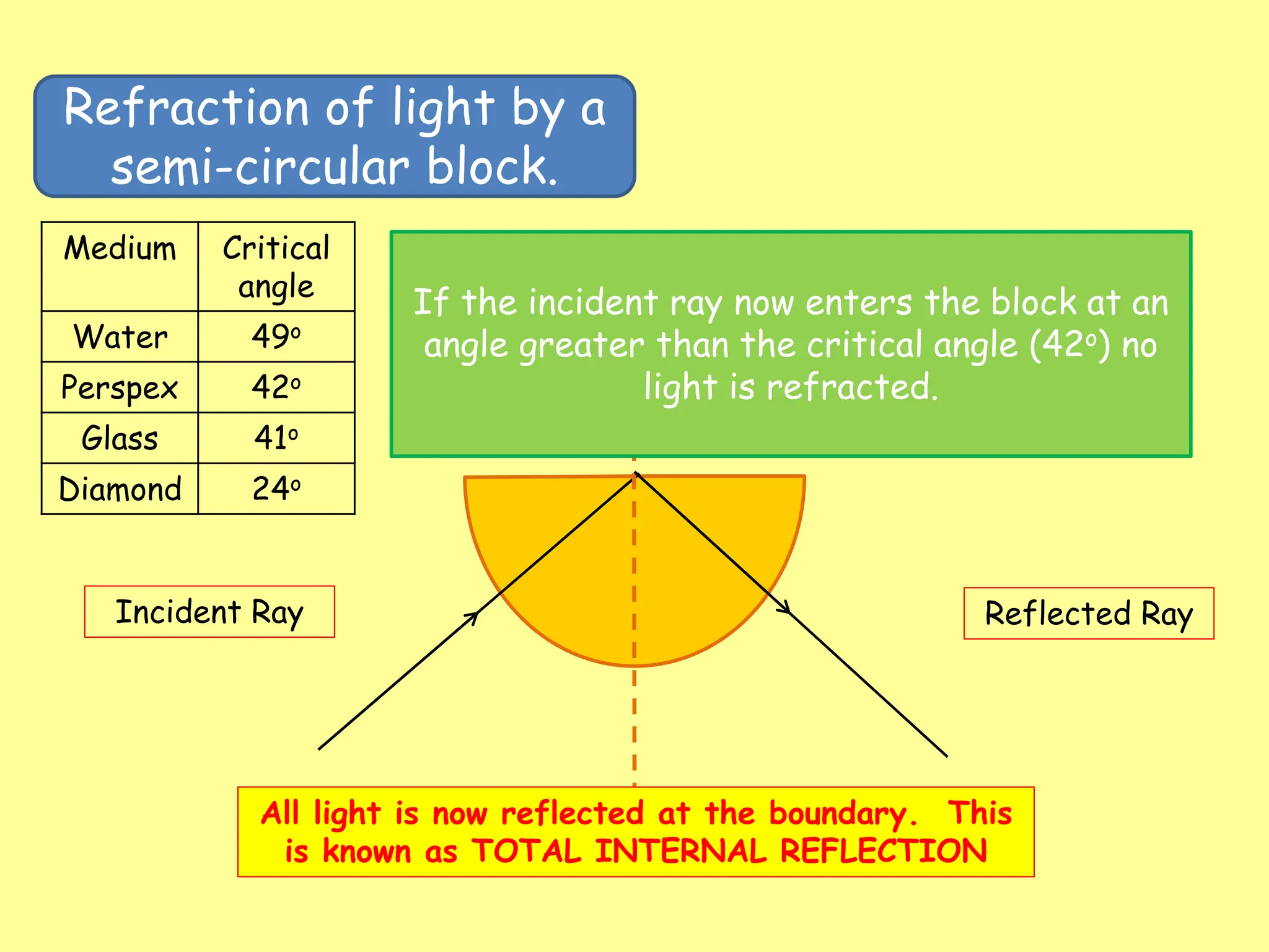
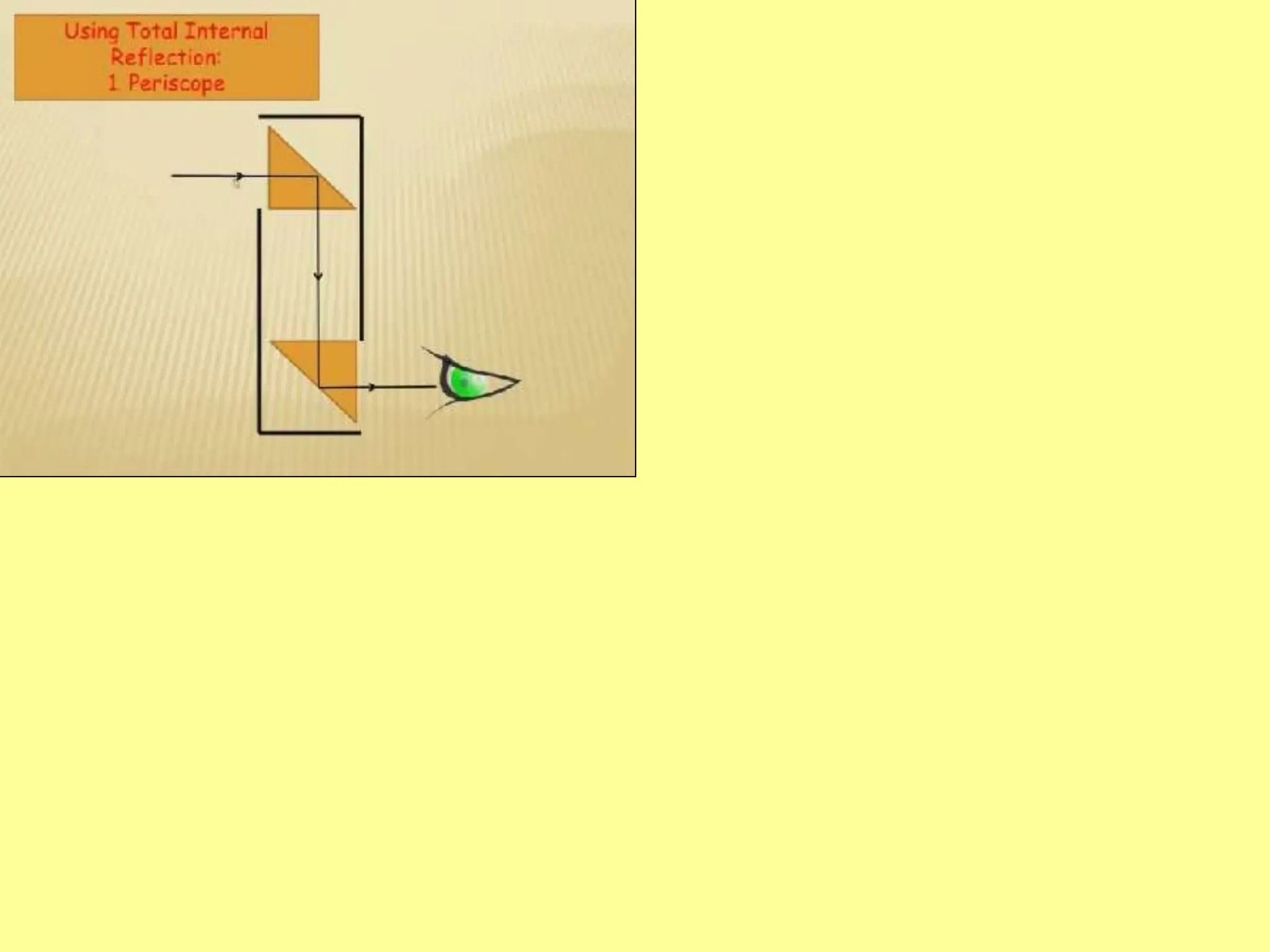
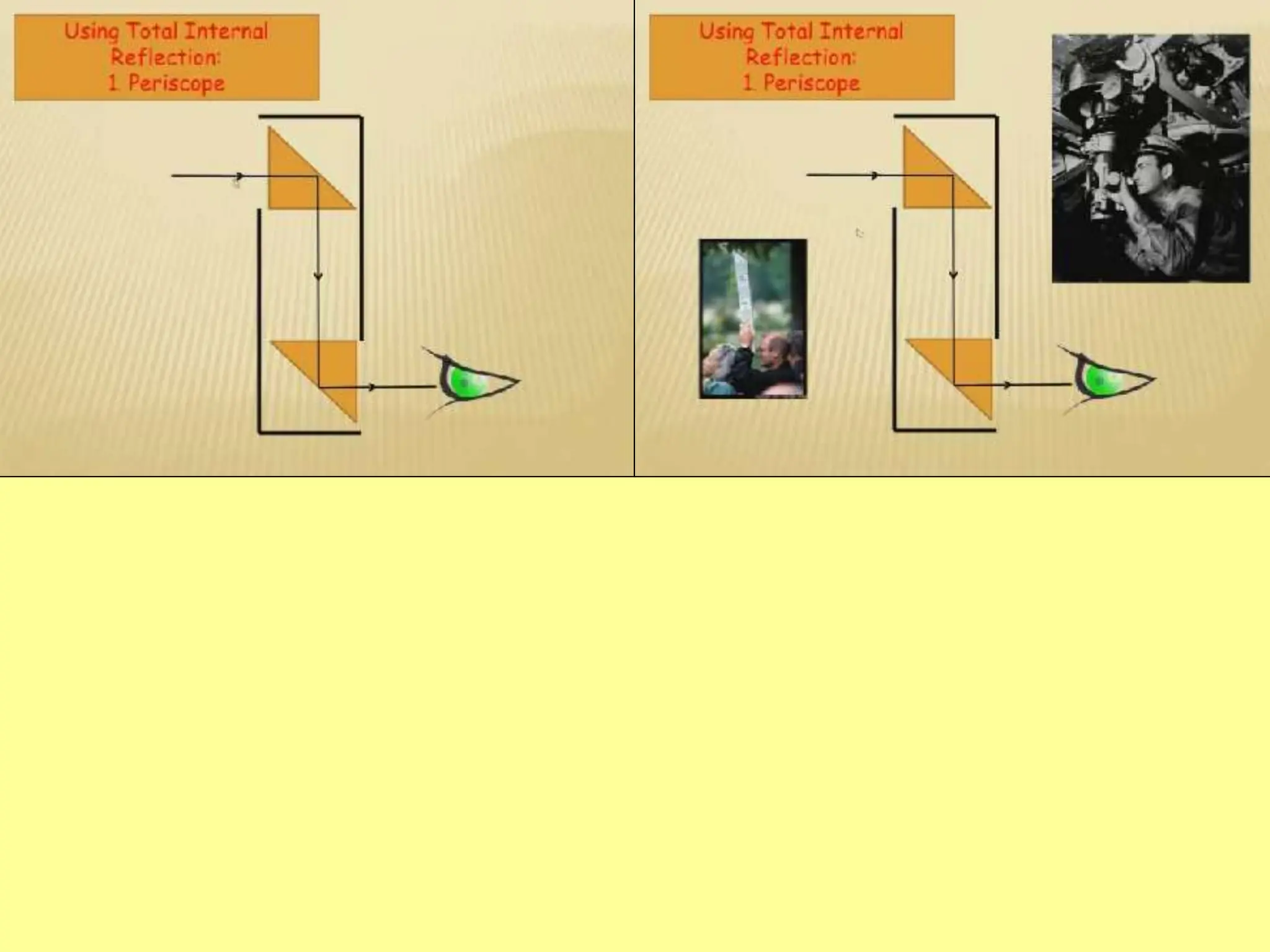
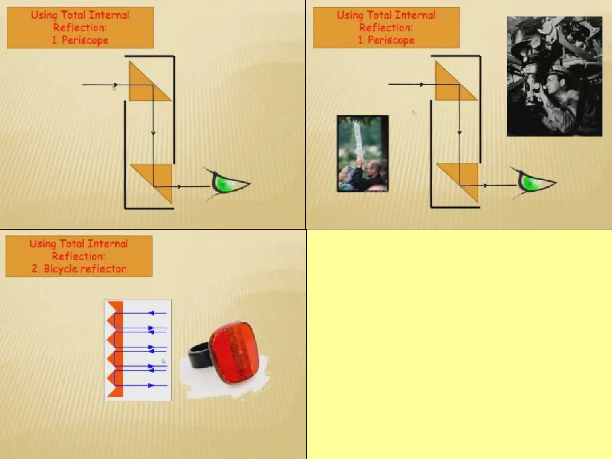
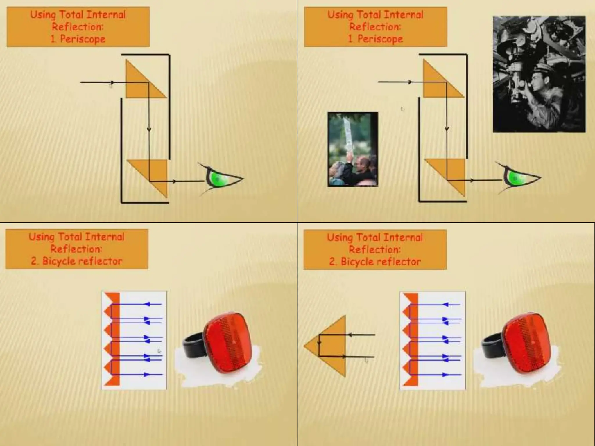
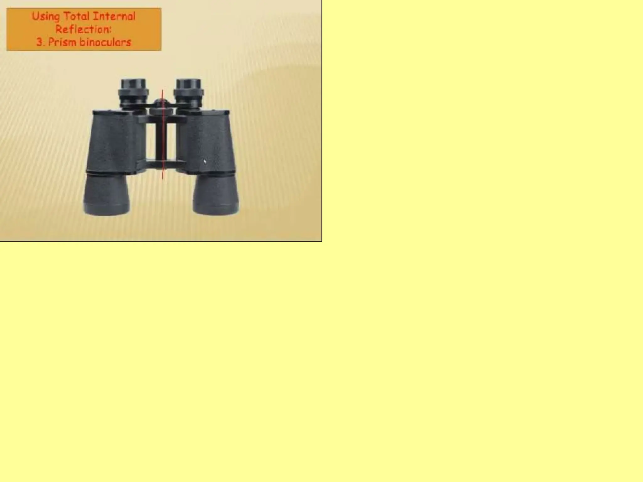
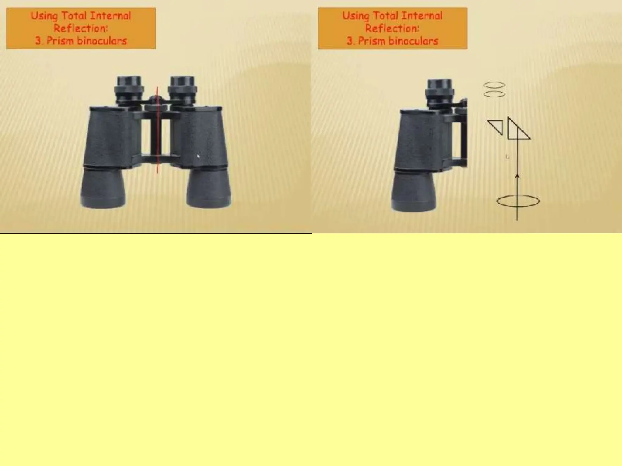
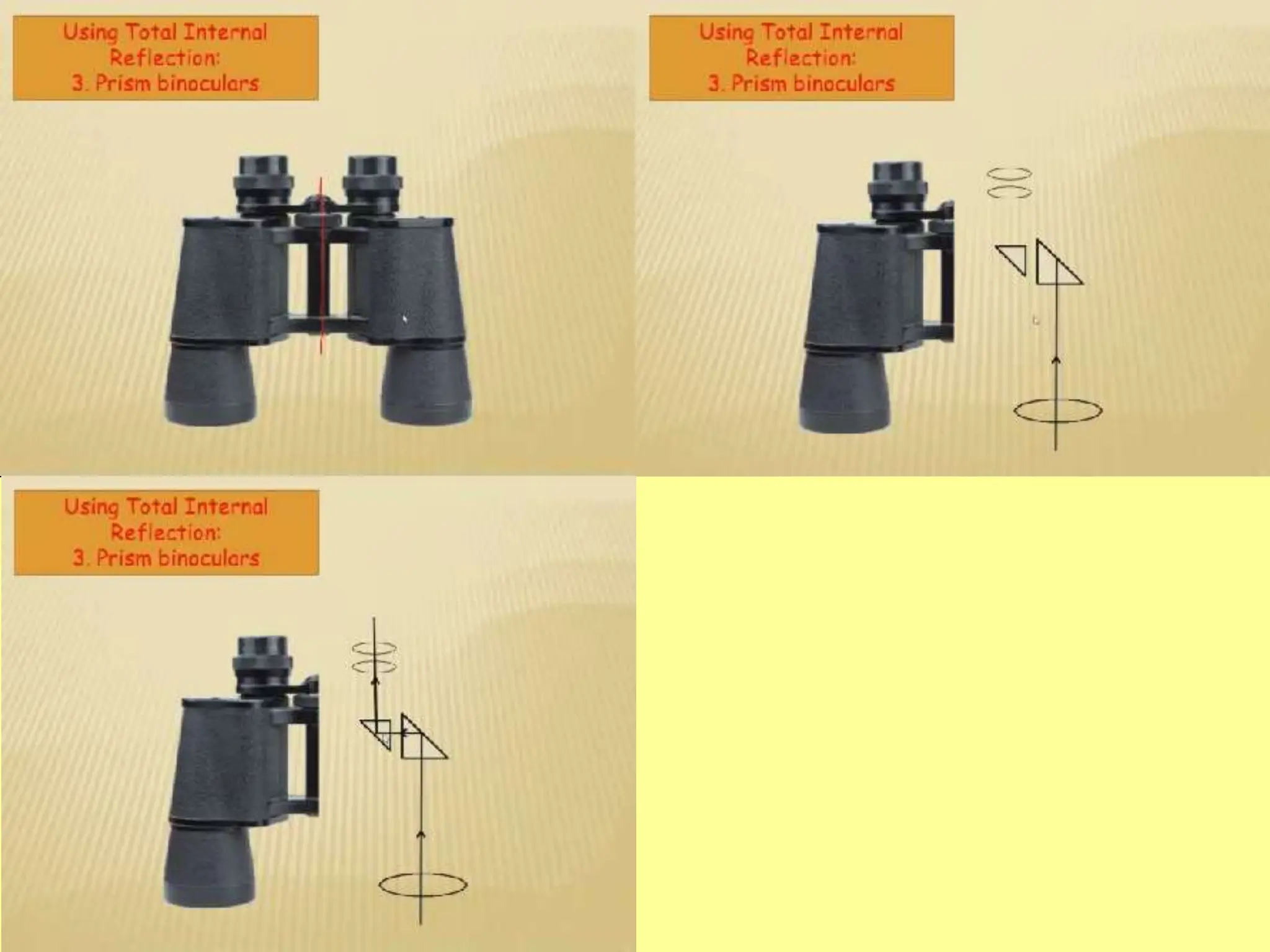
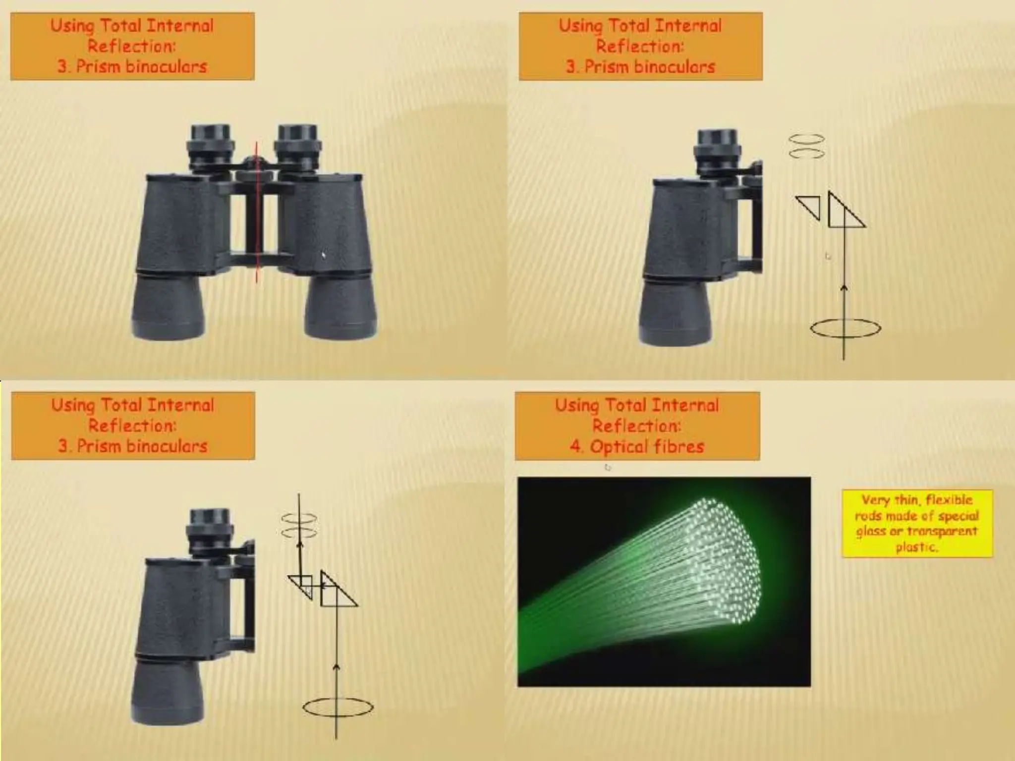
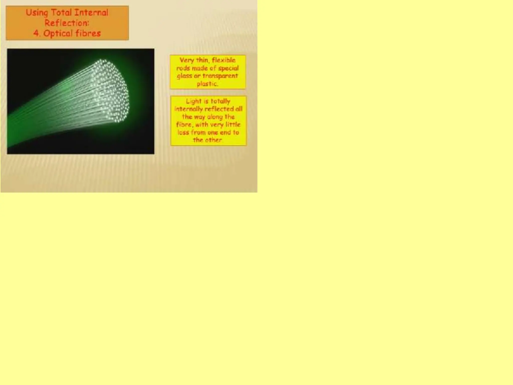
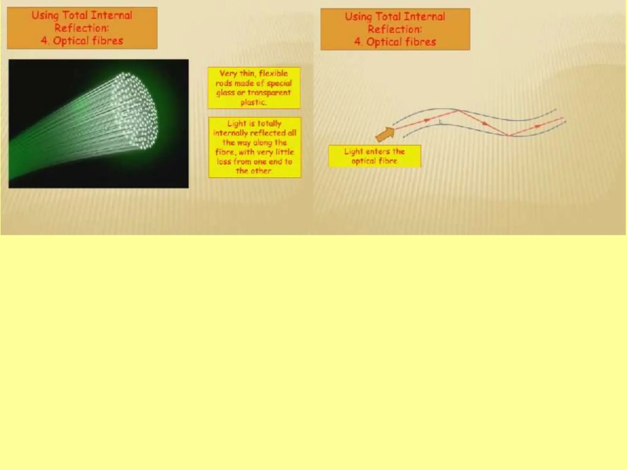
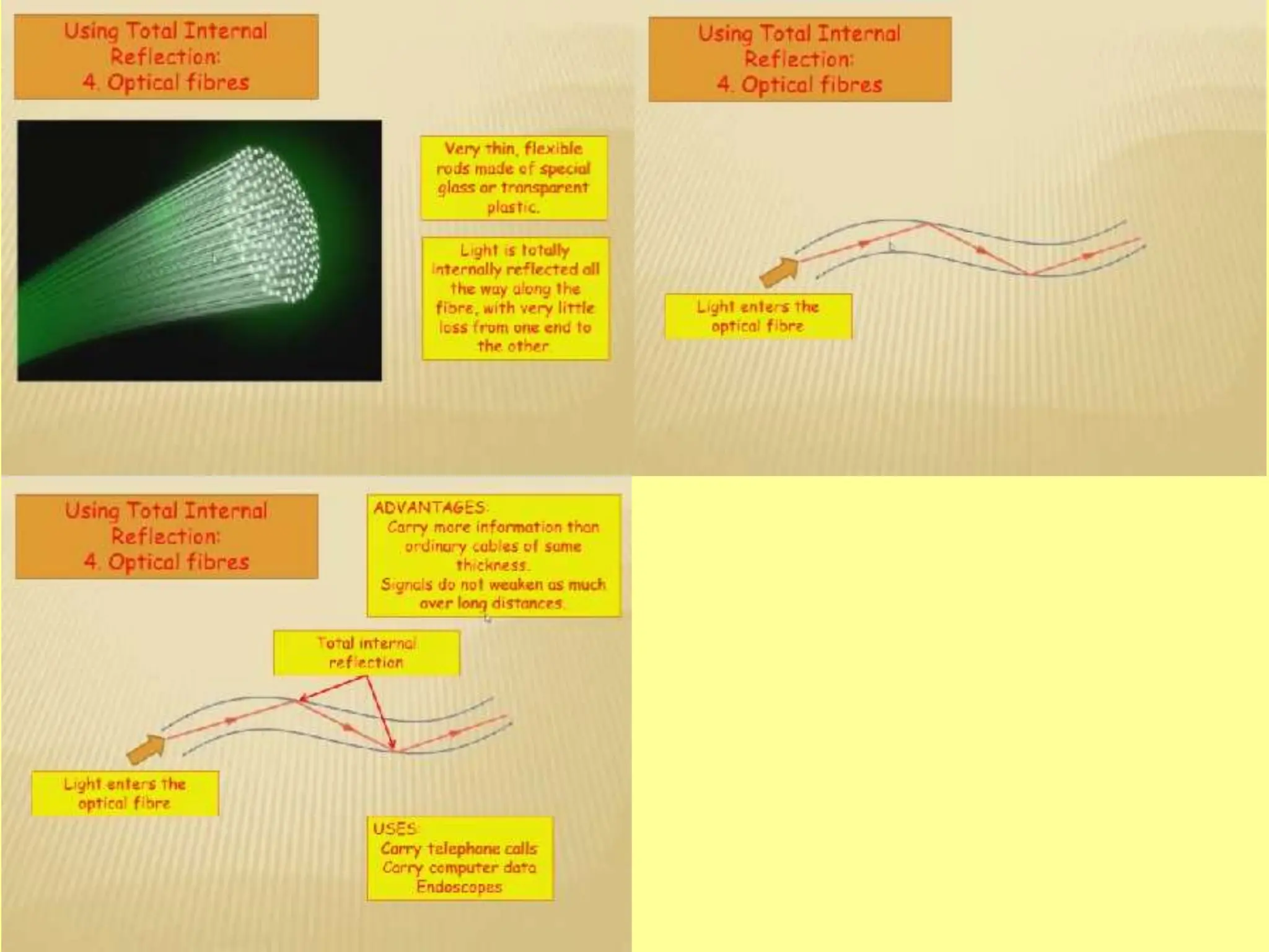
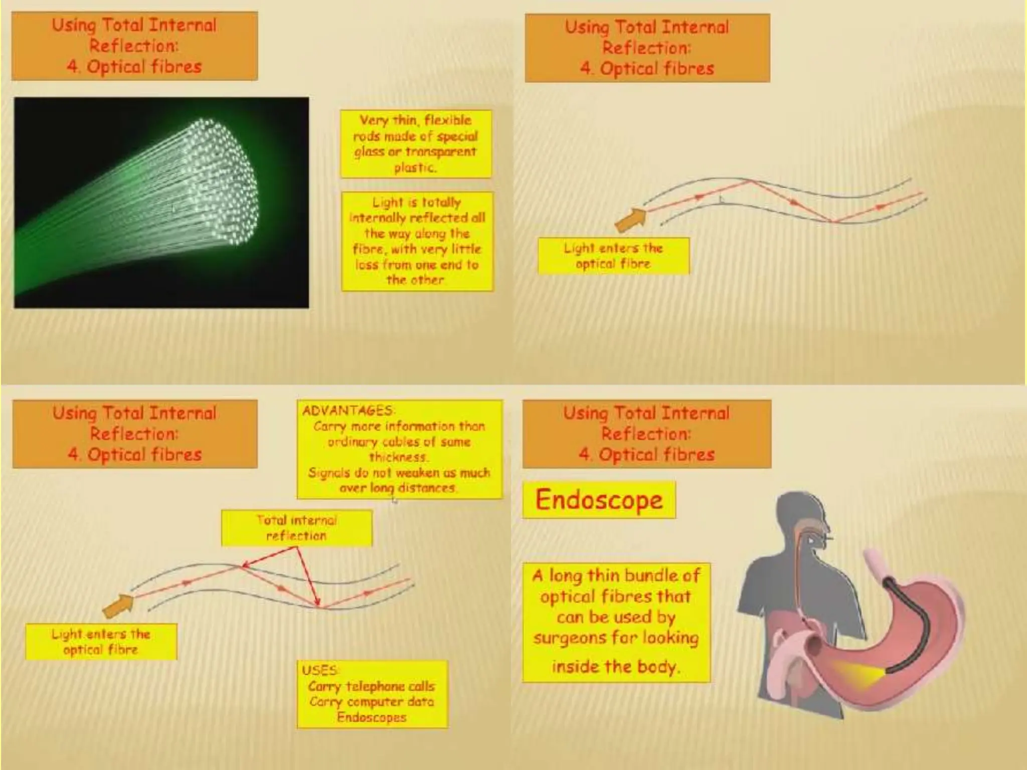
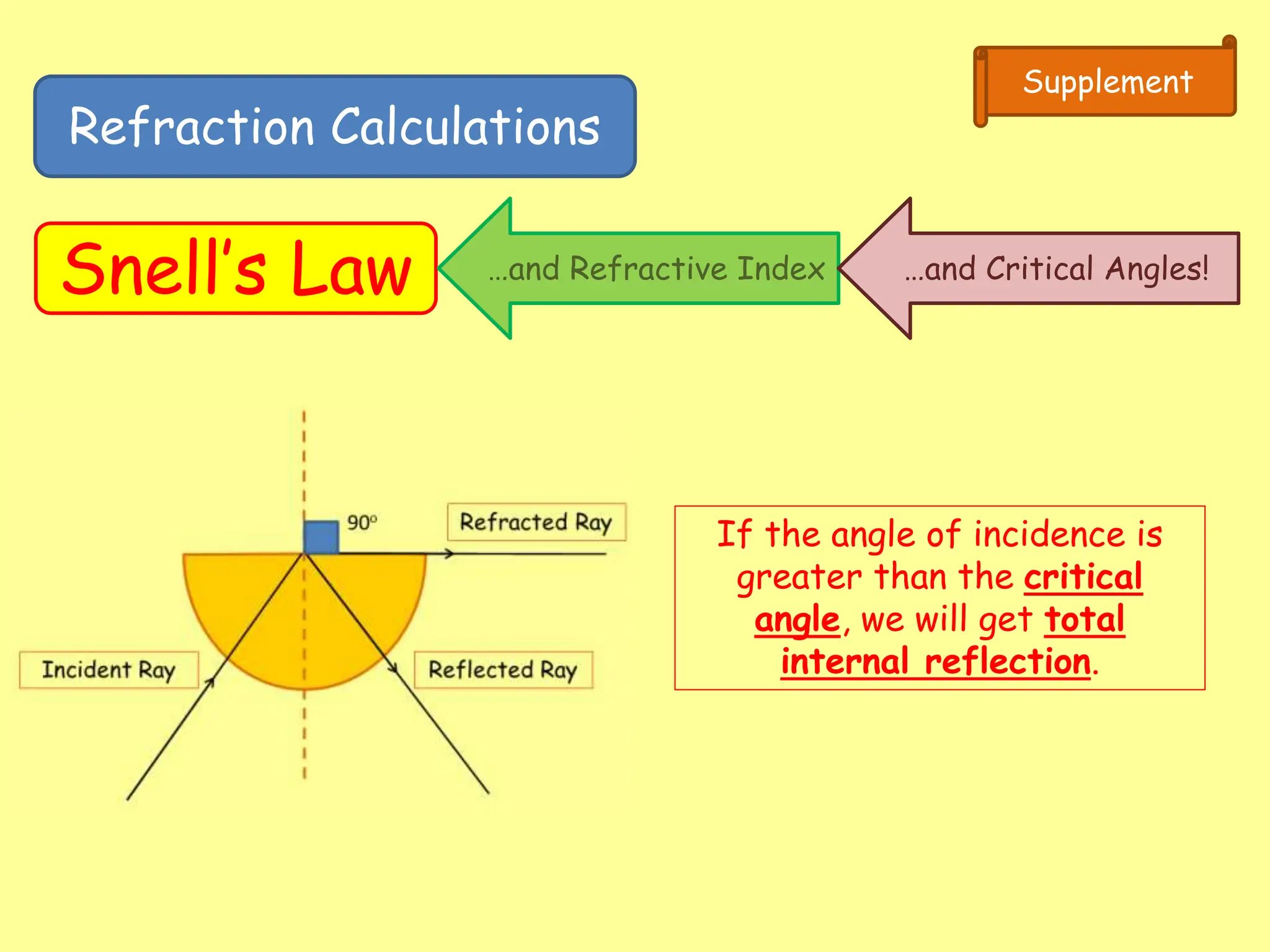
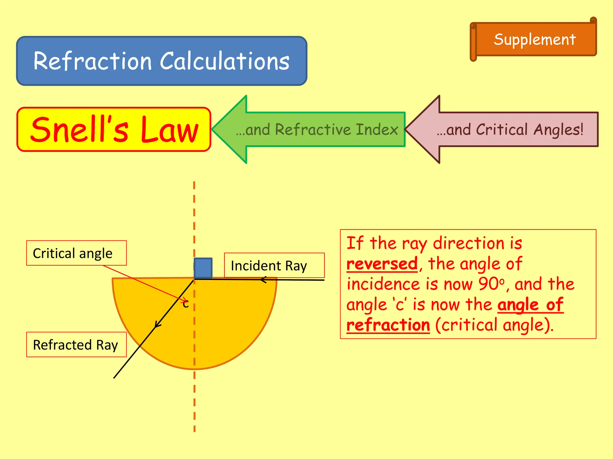
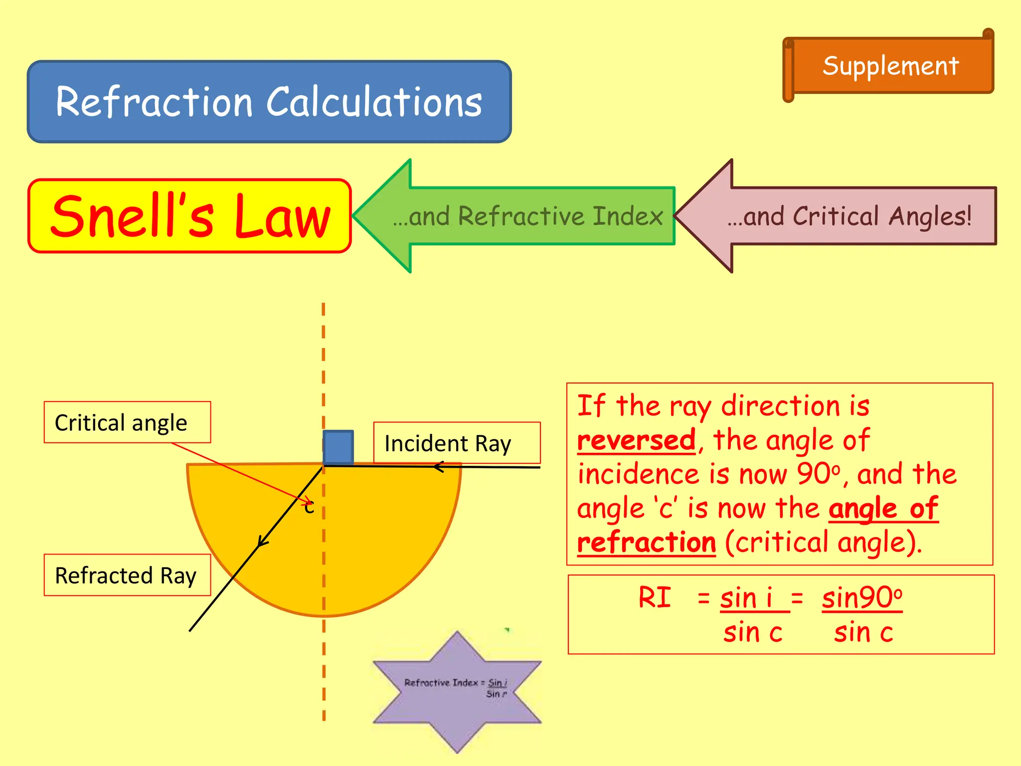
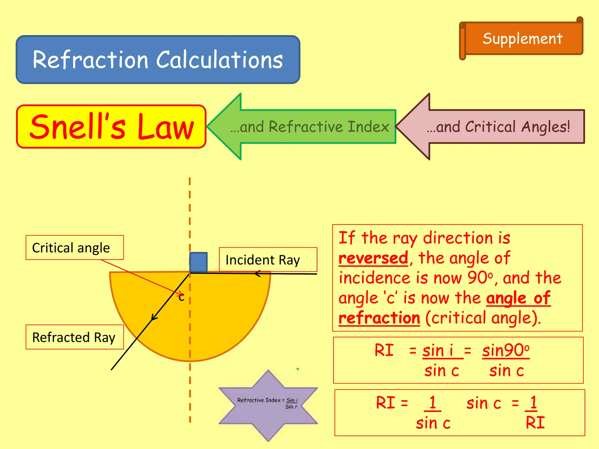
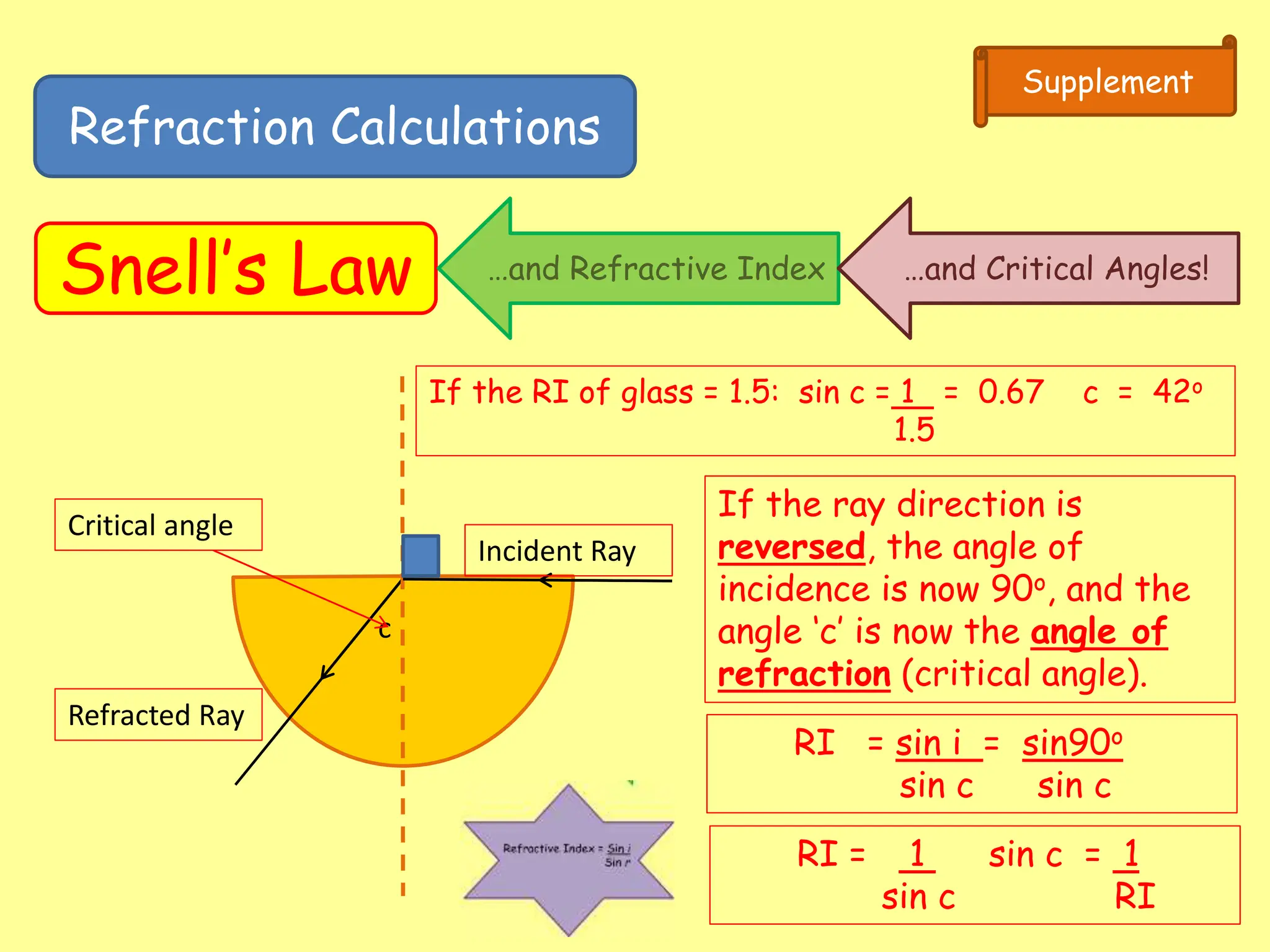
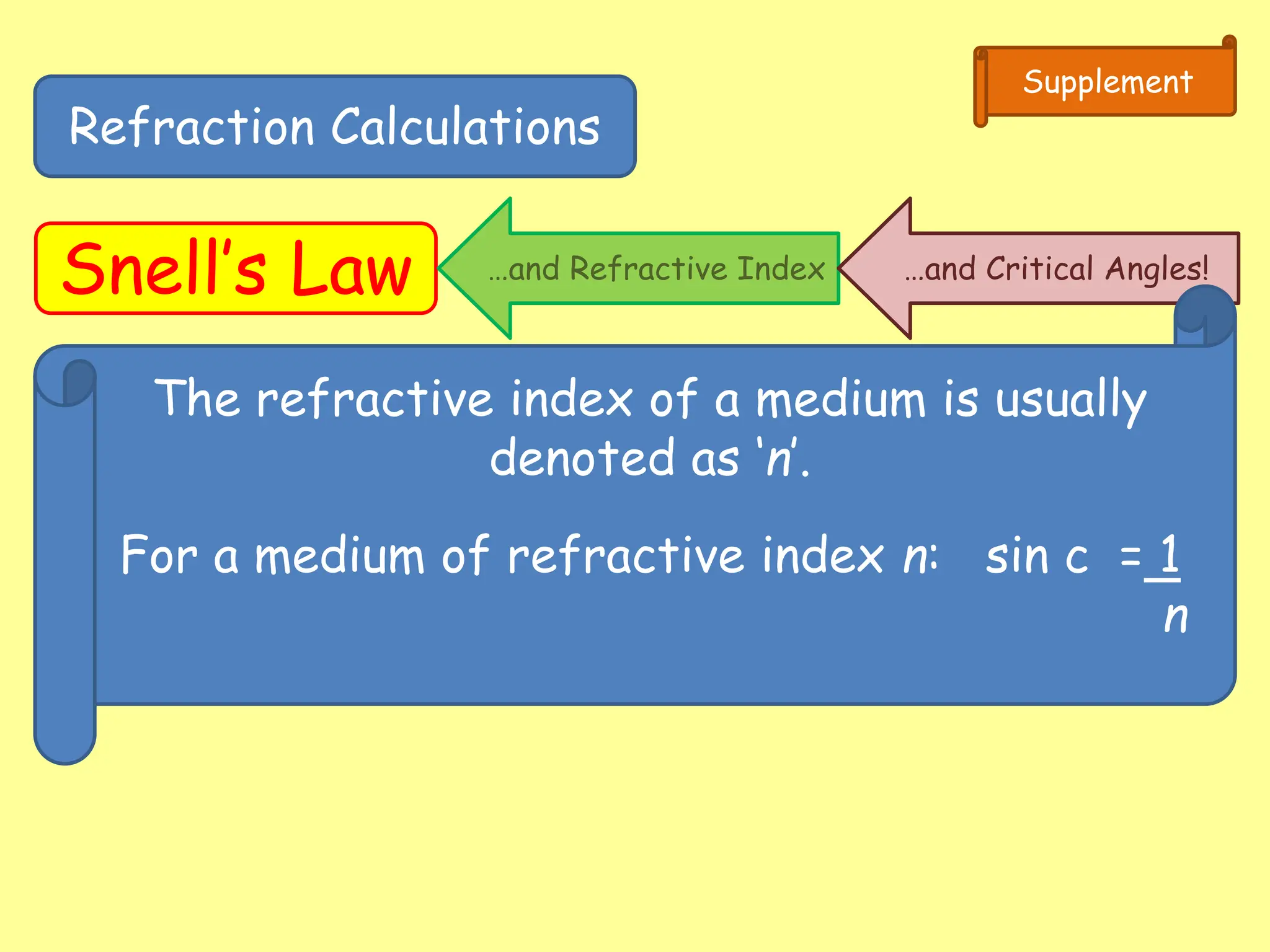
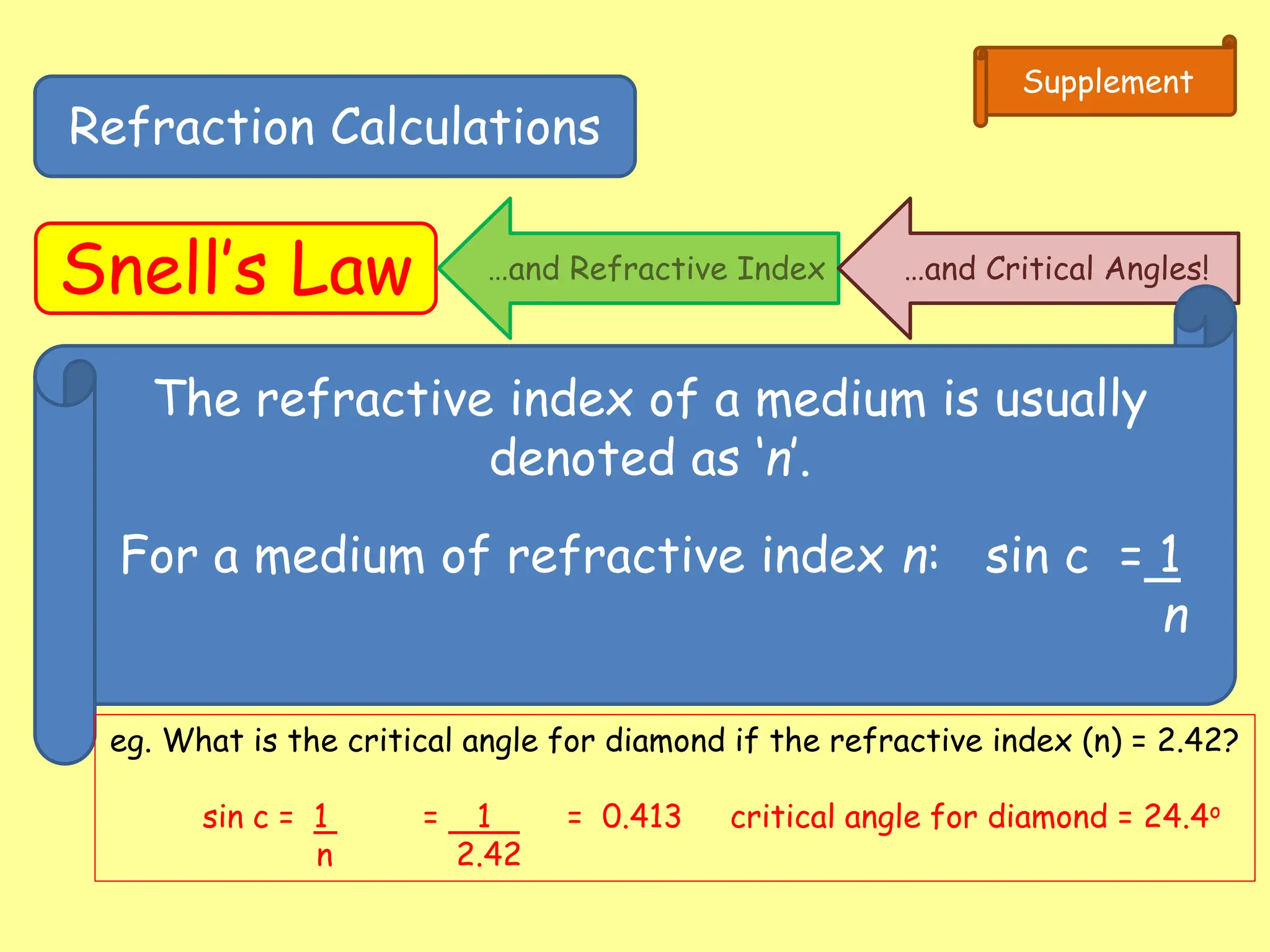
- Total internal reflection, which occurs when light passes from an optically dense medium to a less dense medium at an angle greater than the critical angle.
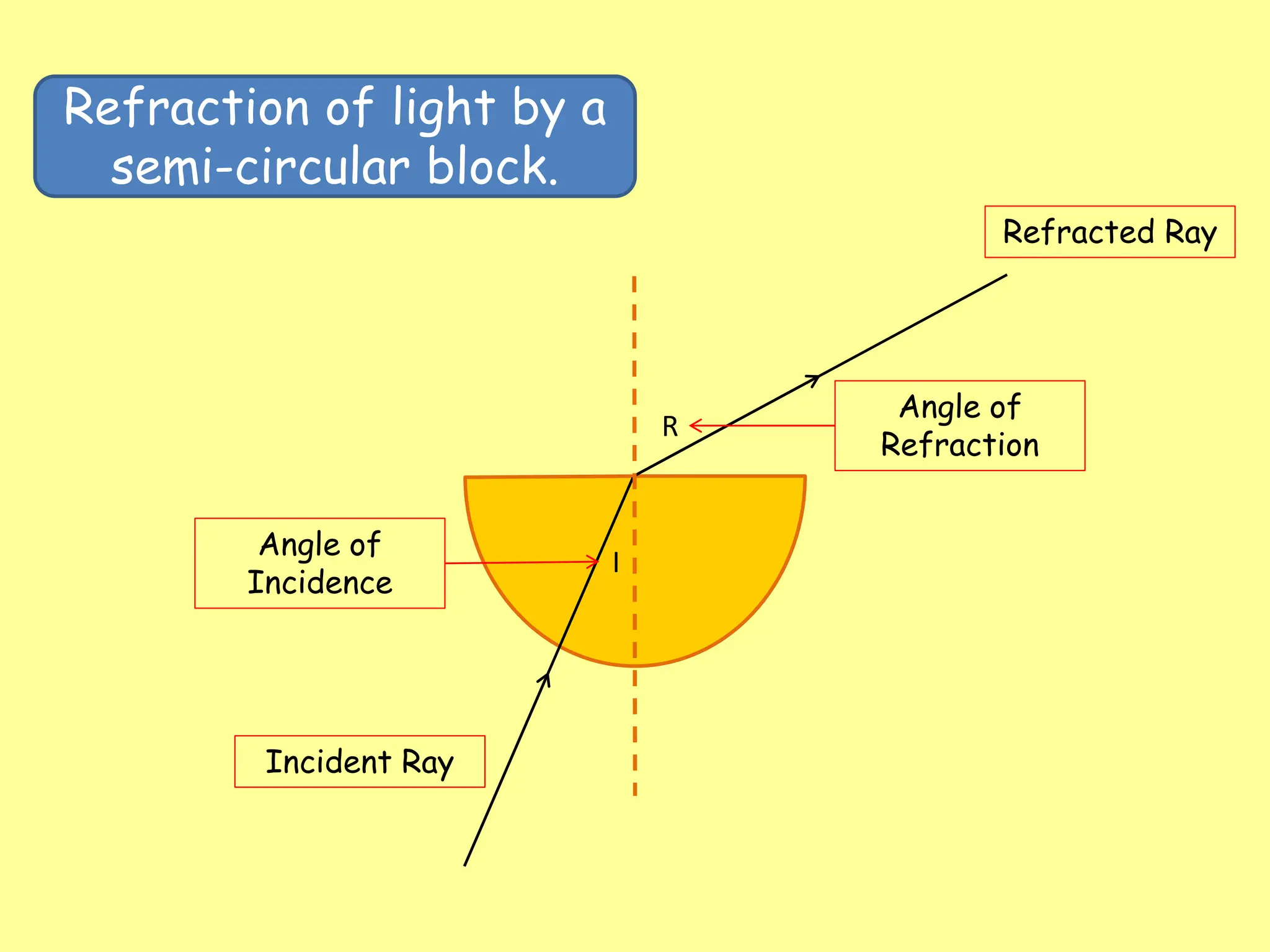
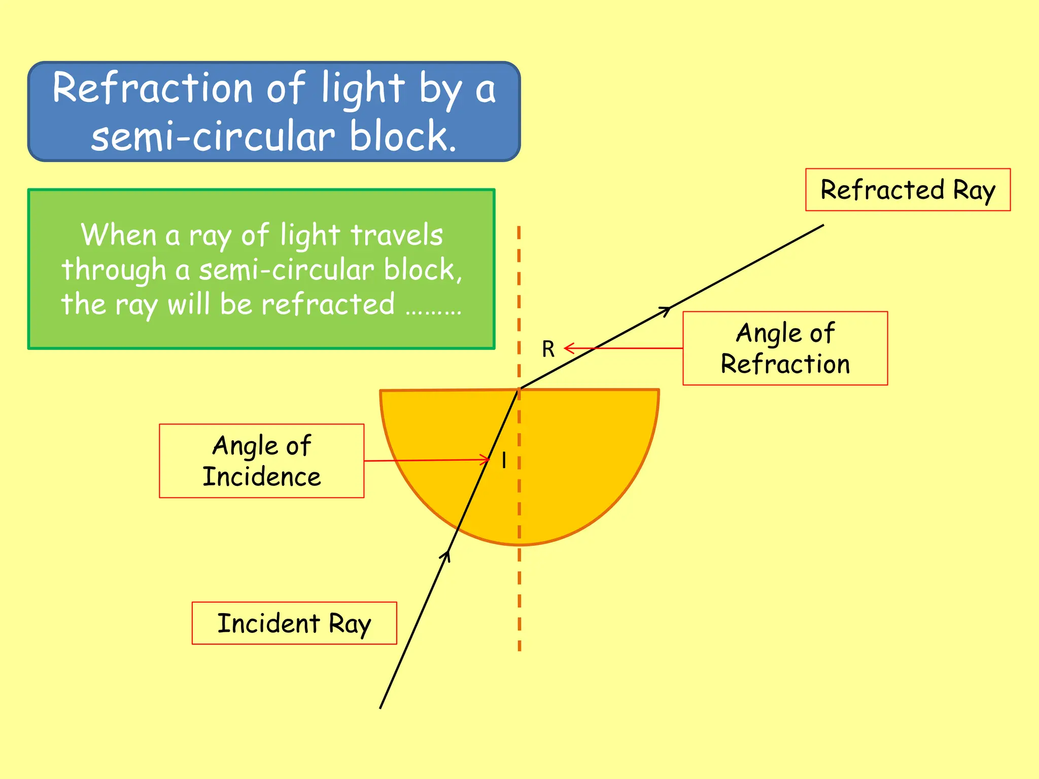
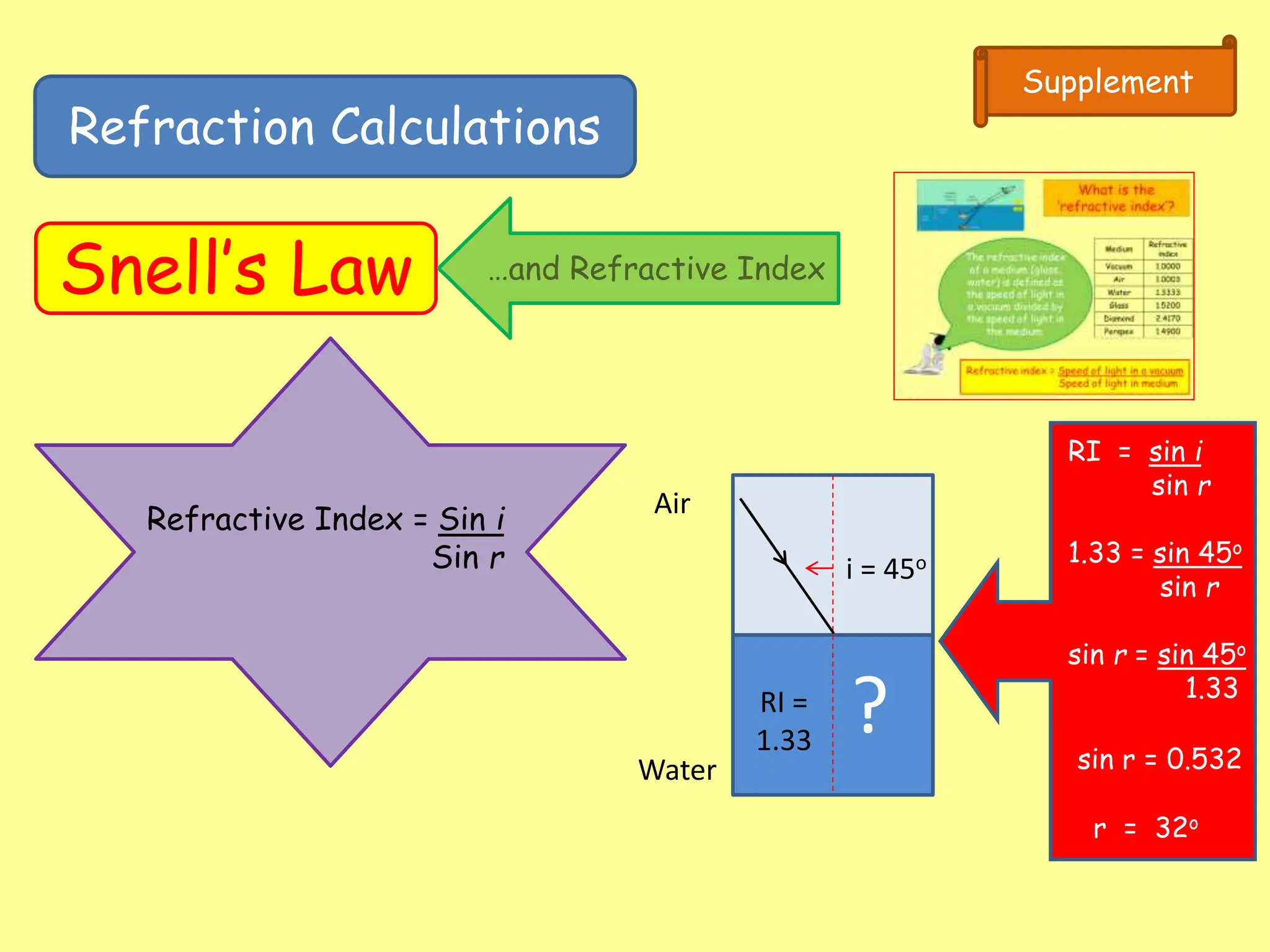
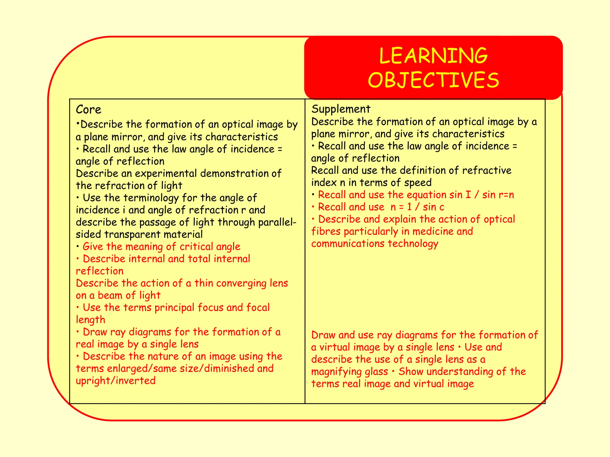
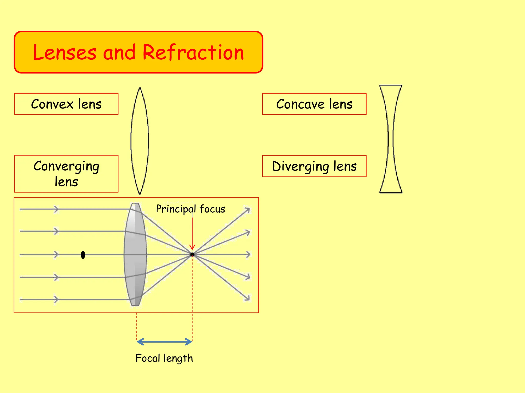
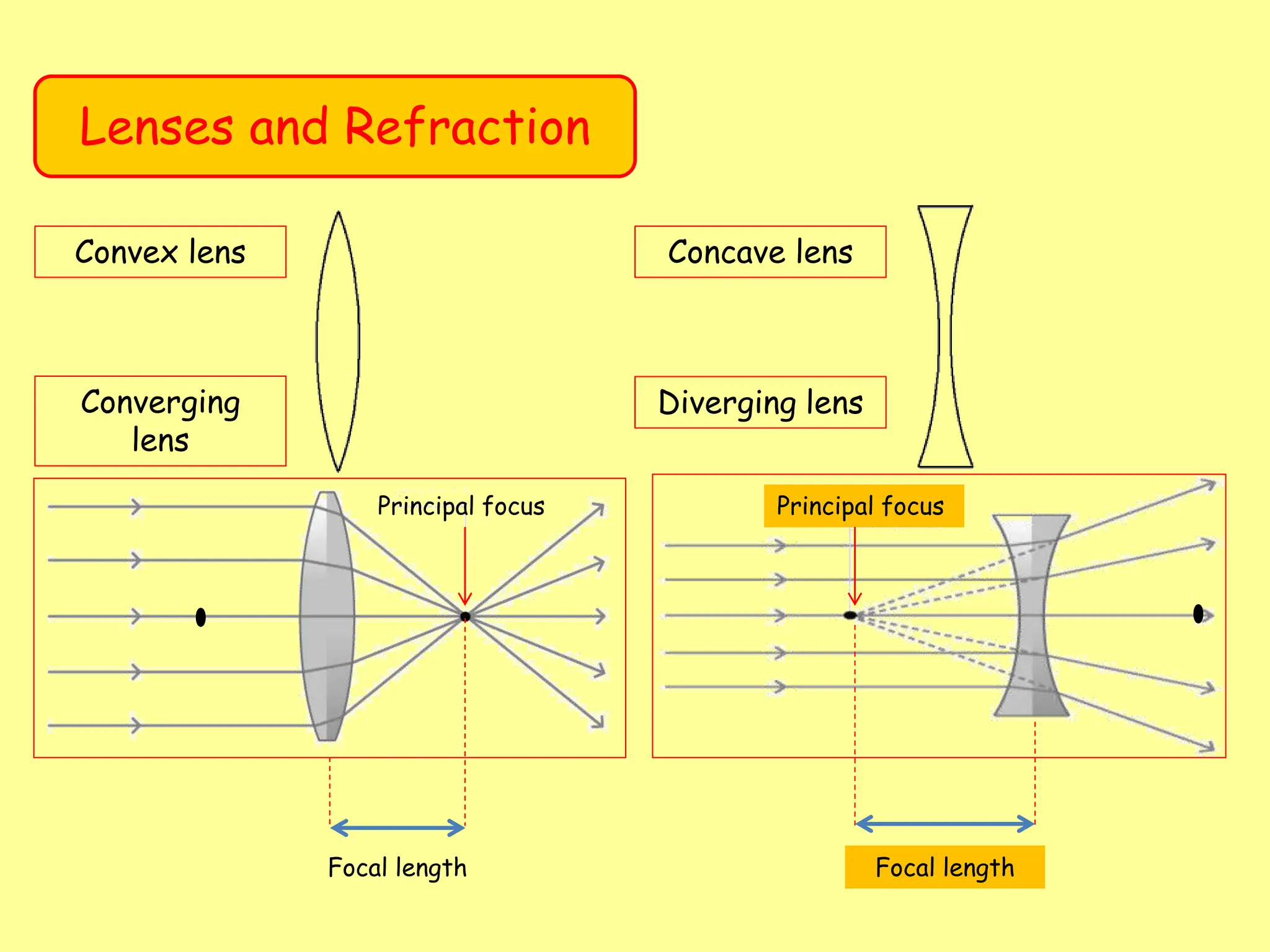
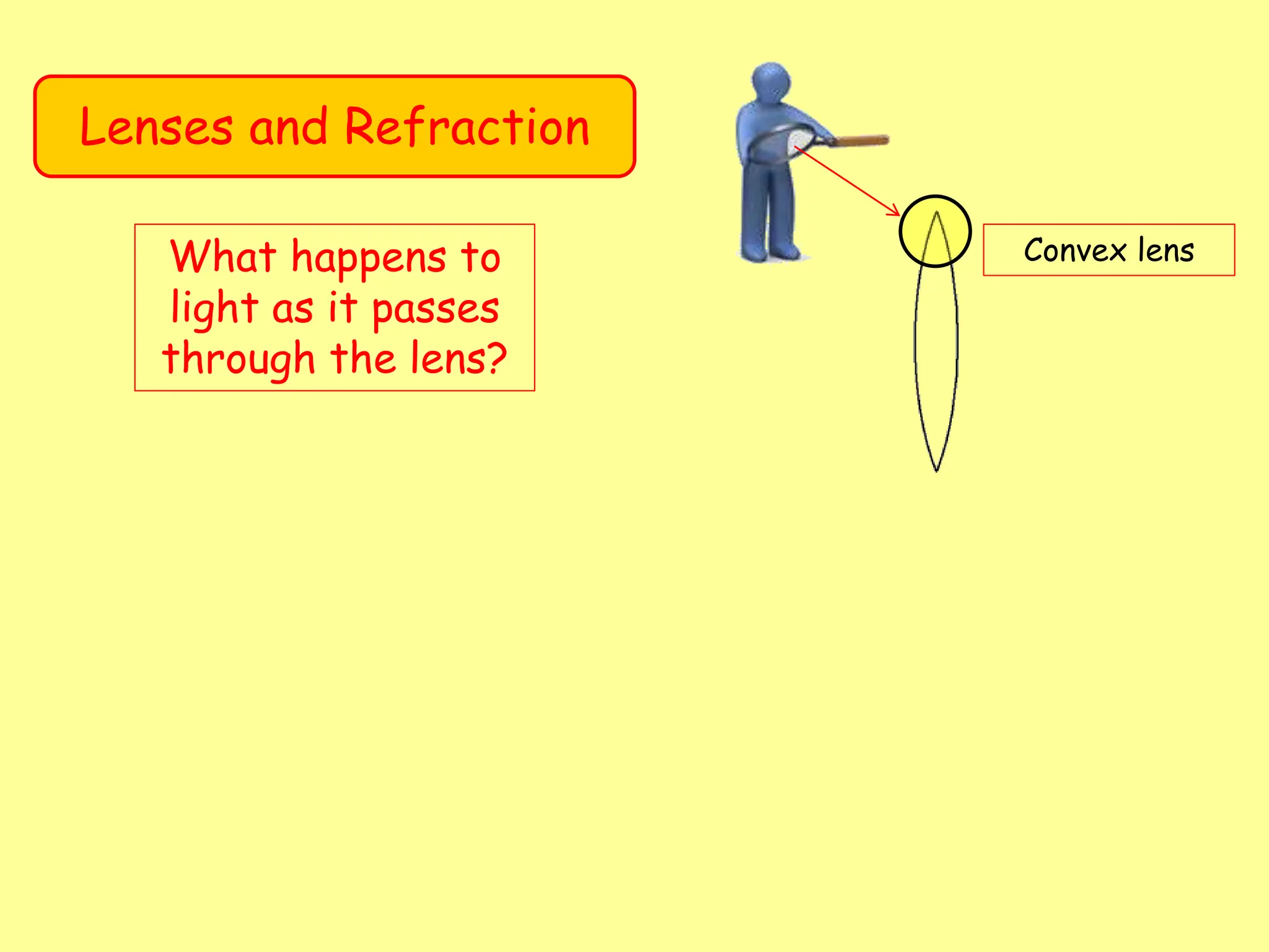
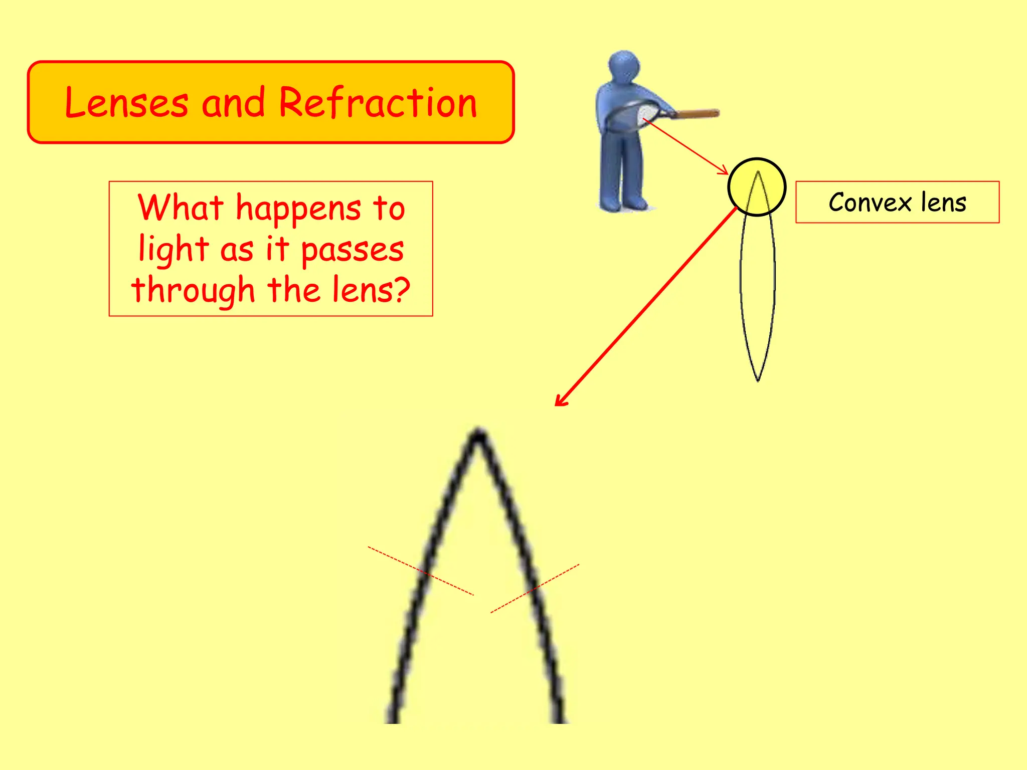
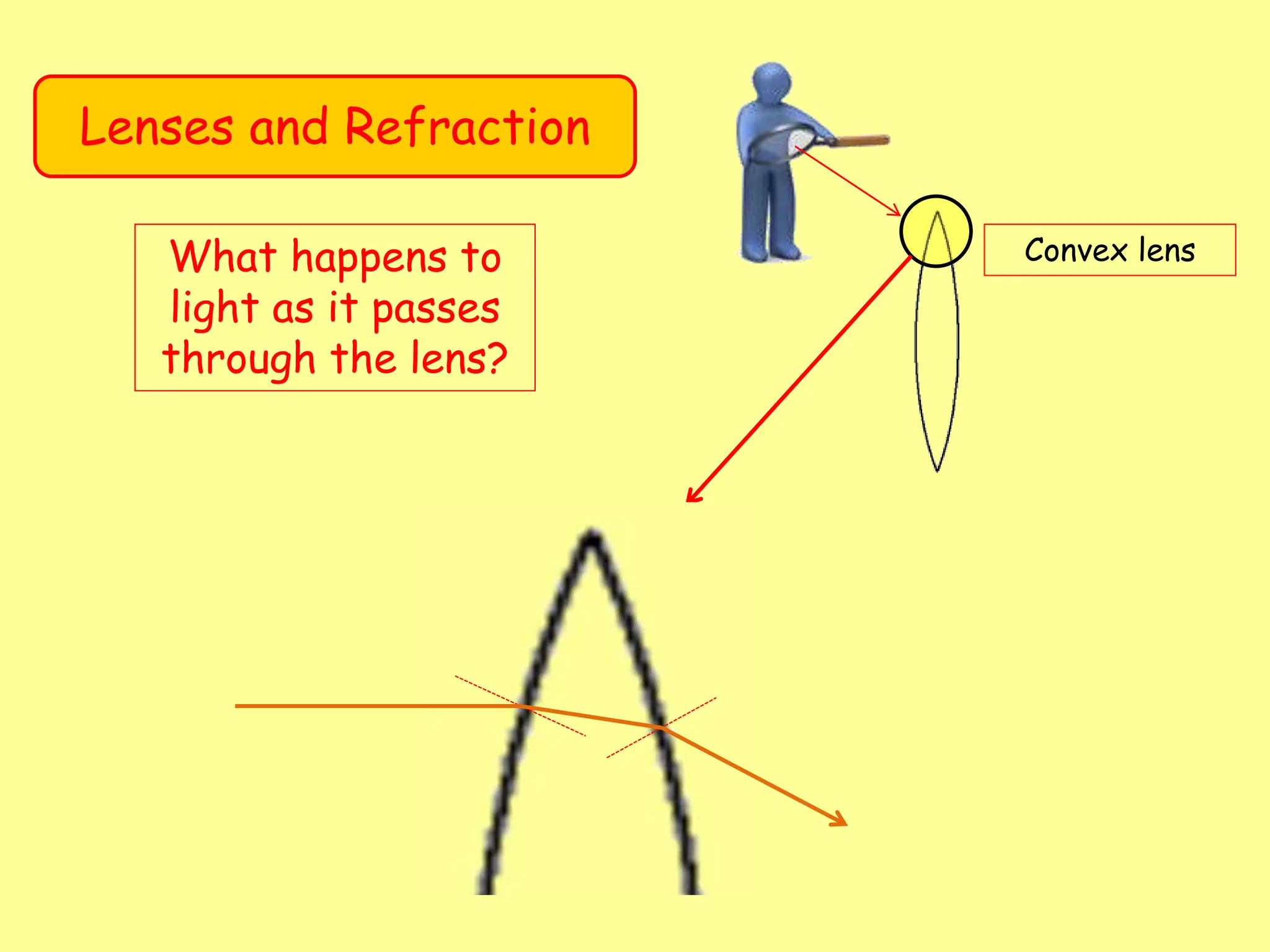
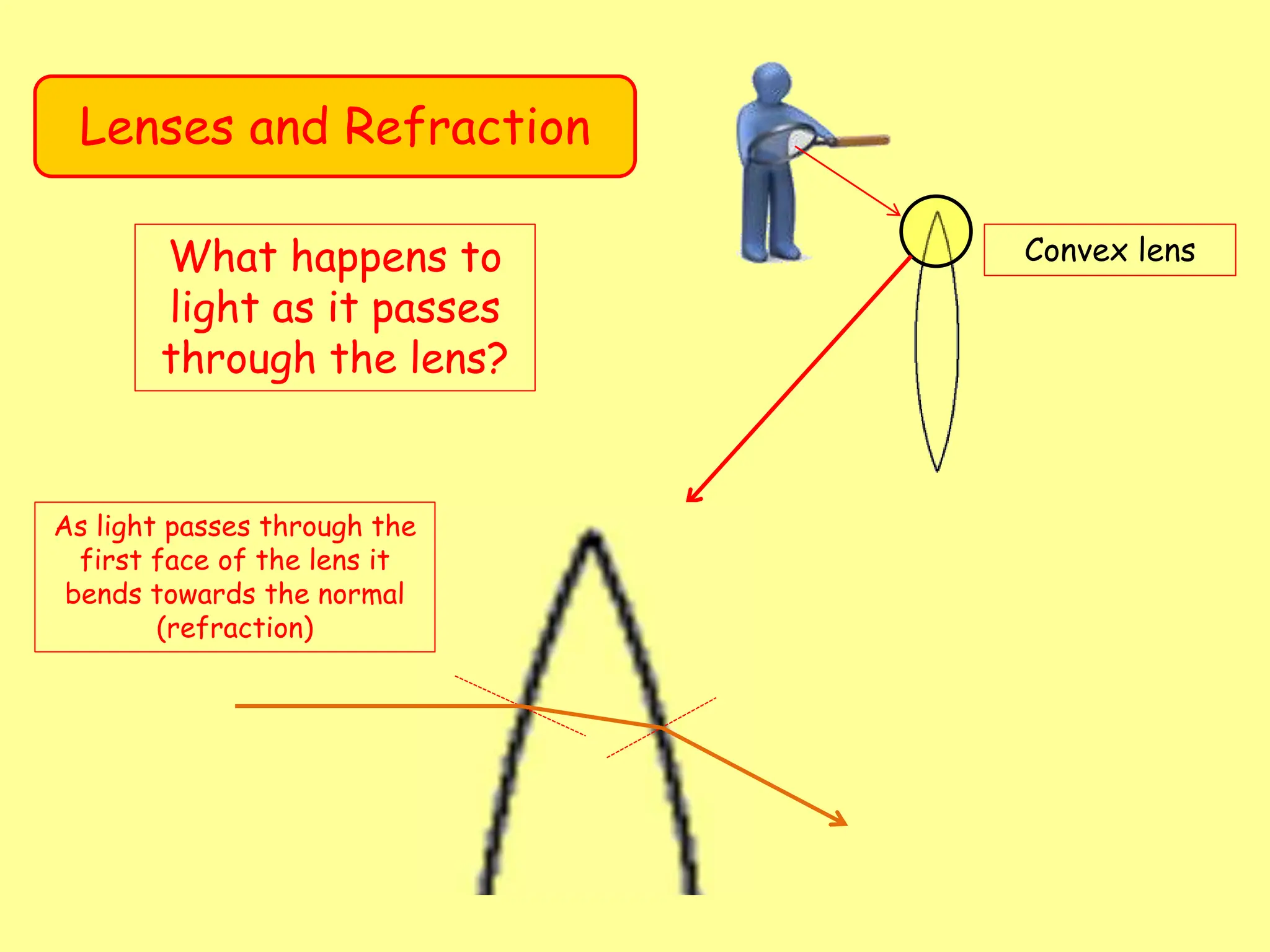
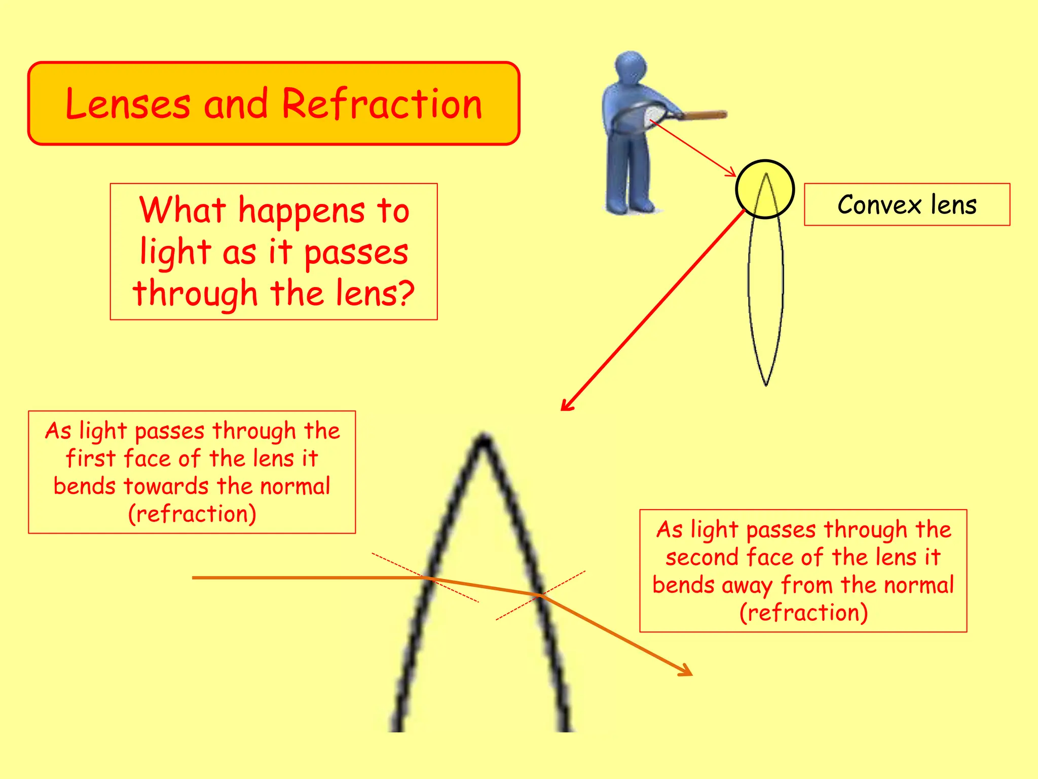
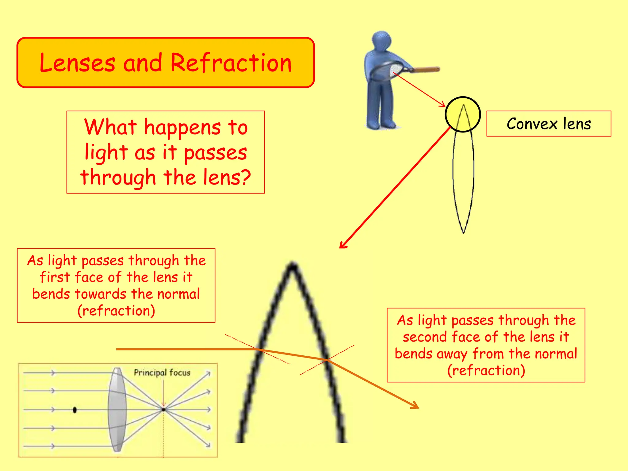
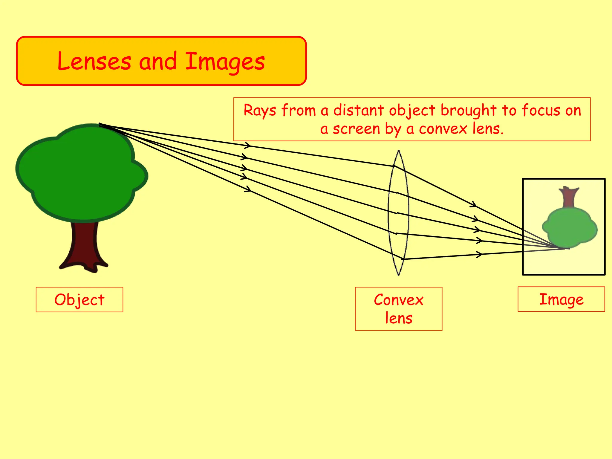
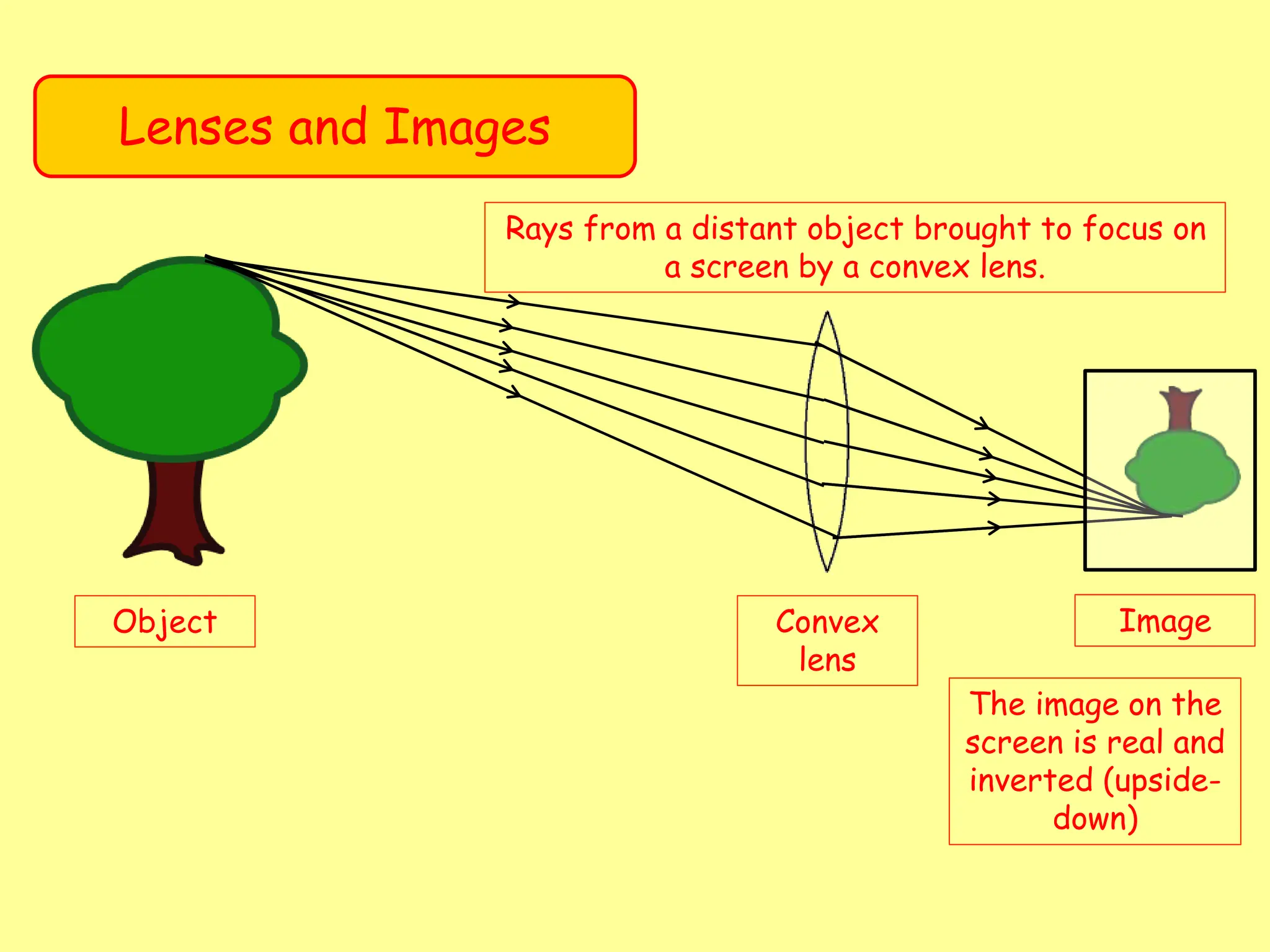
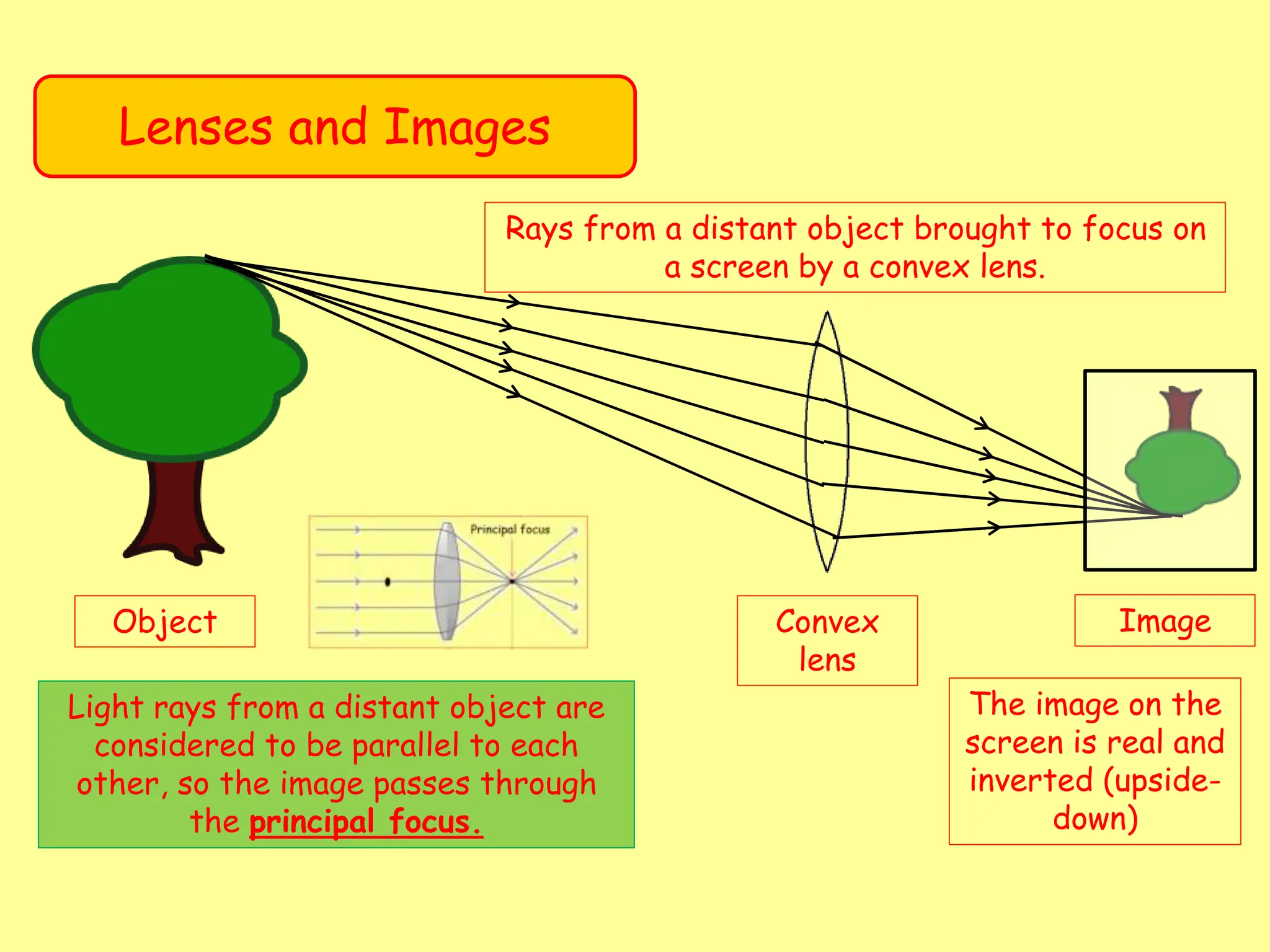
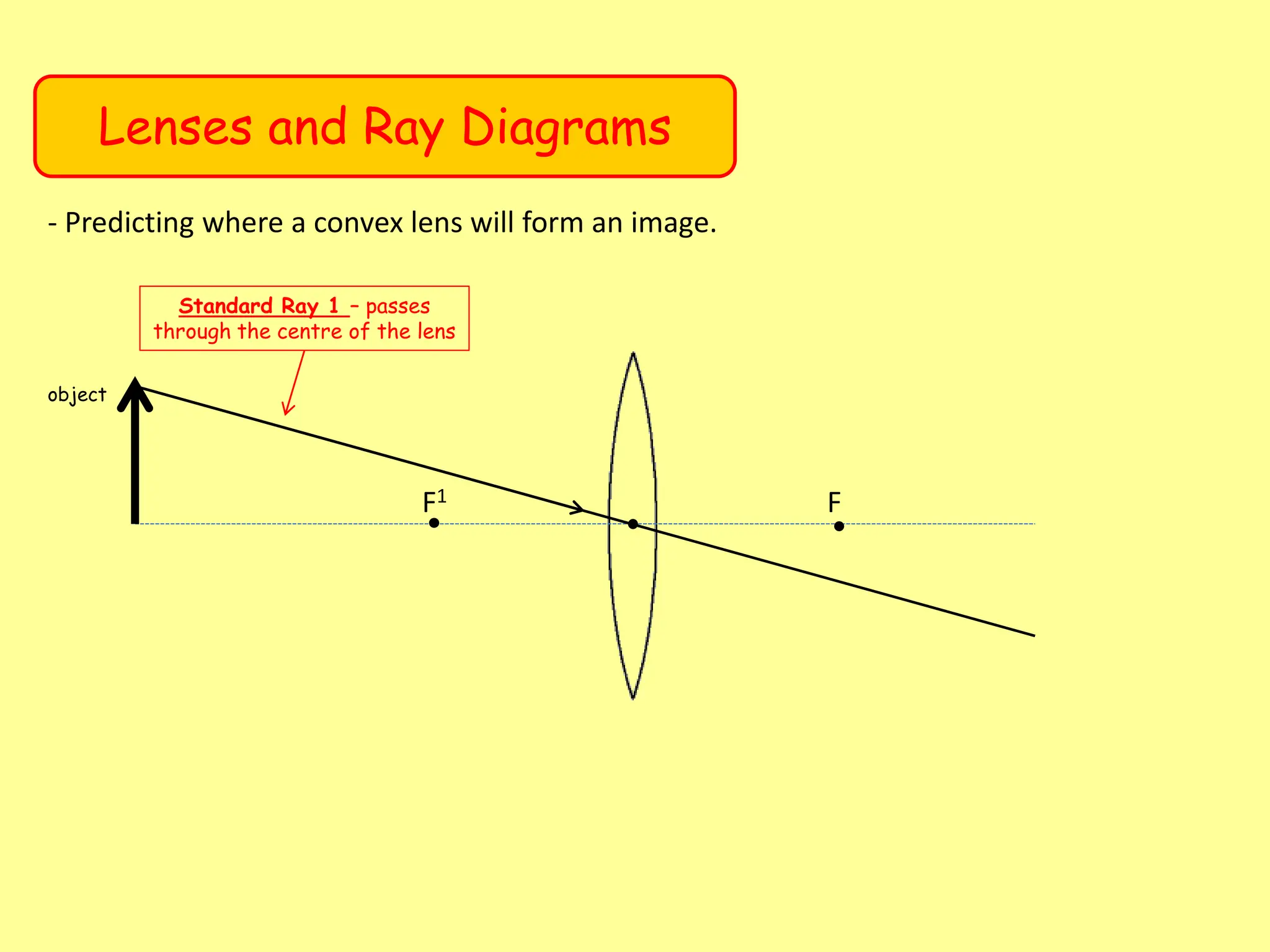
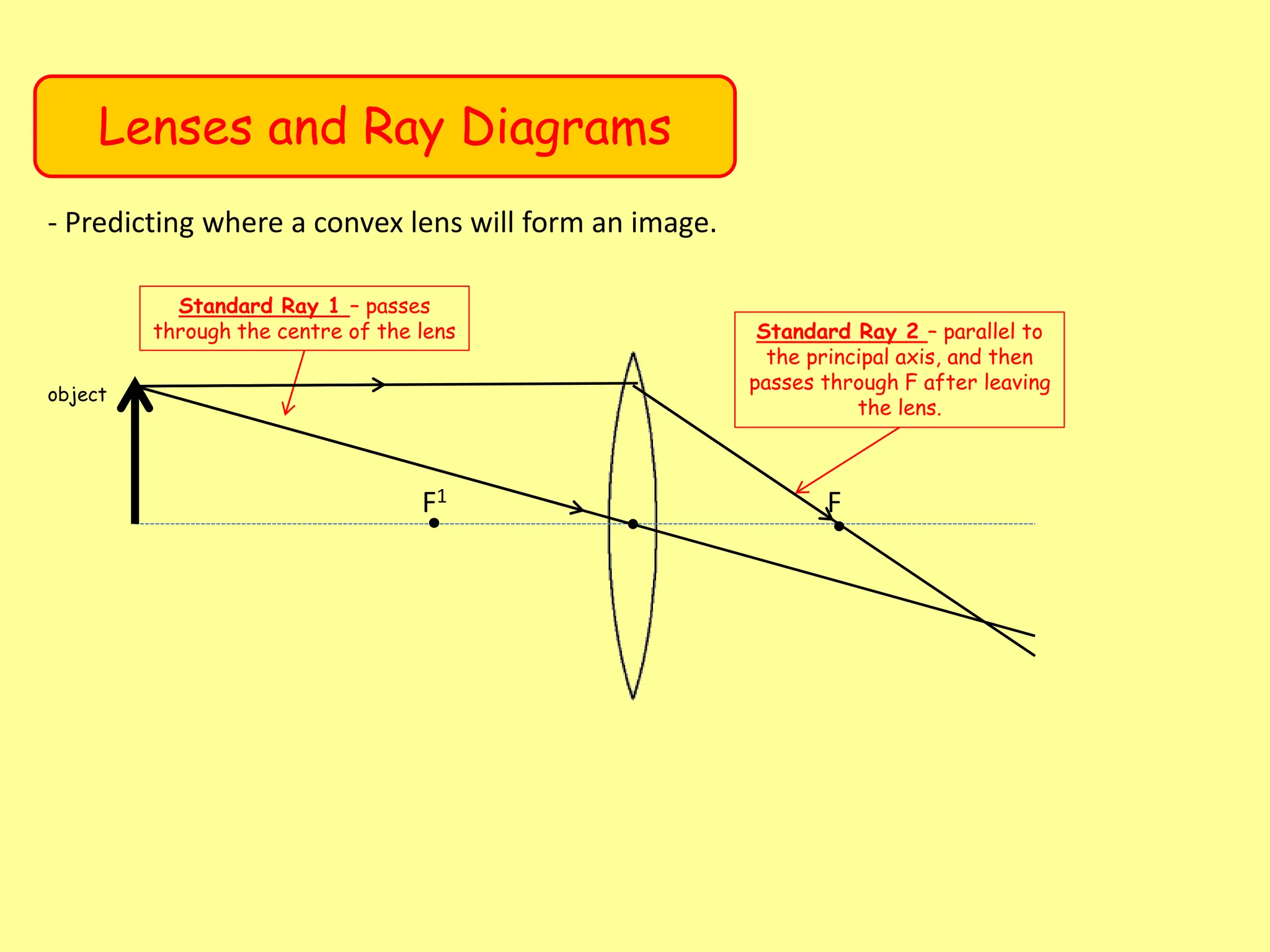
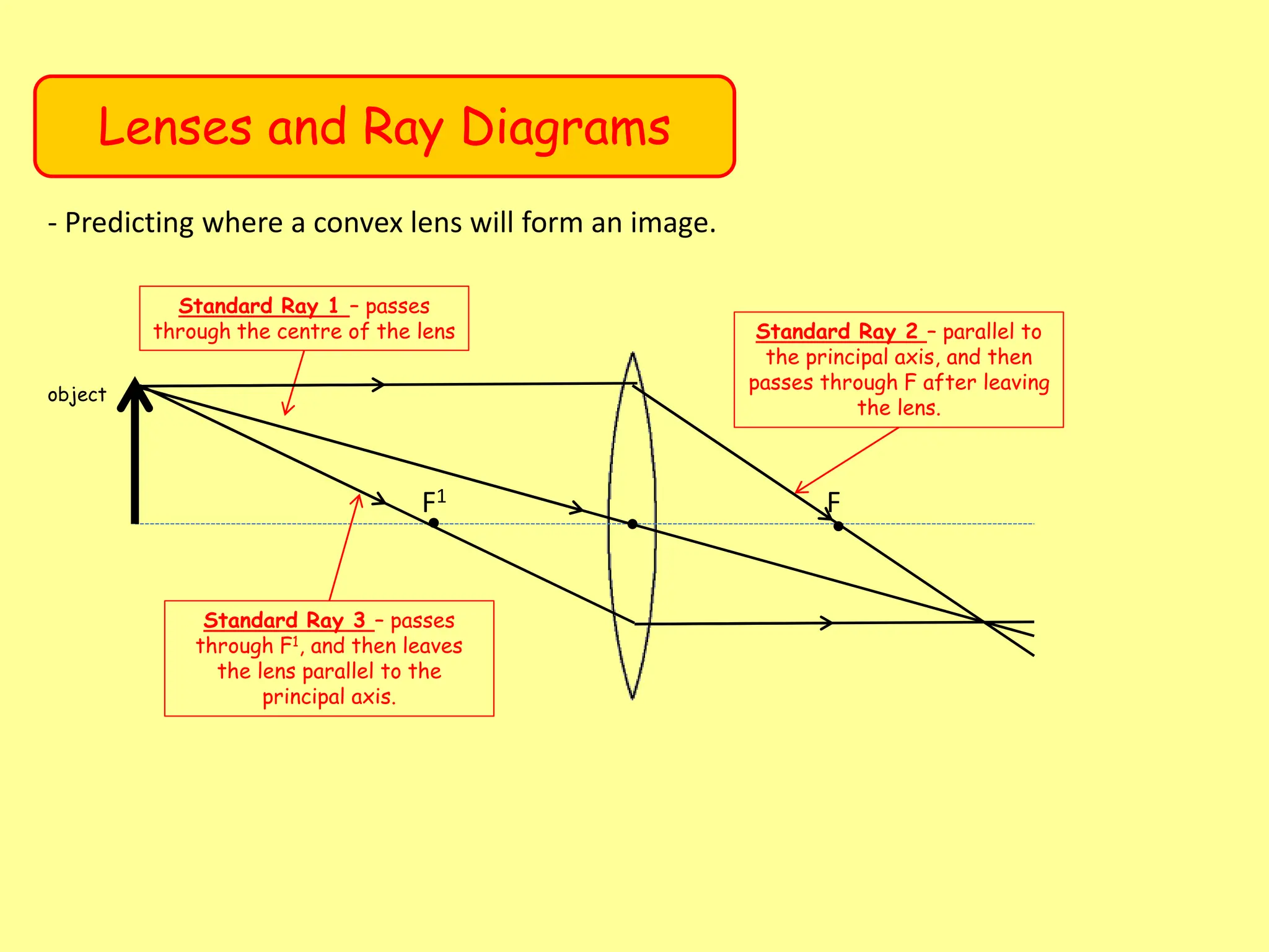
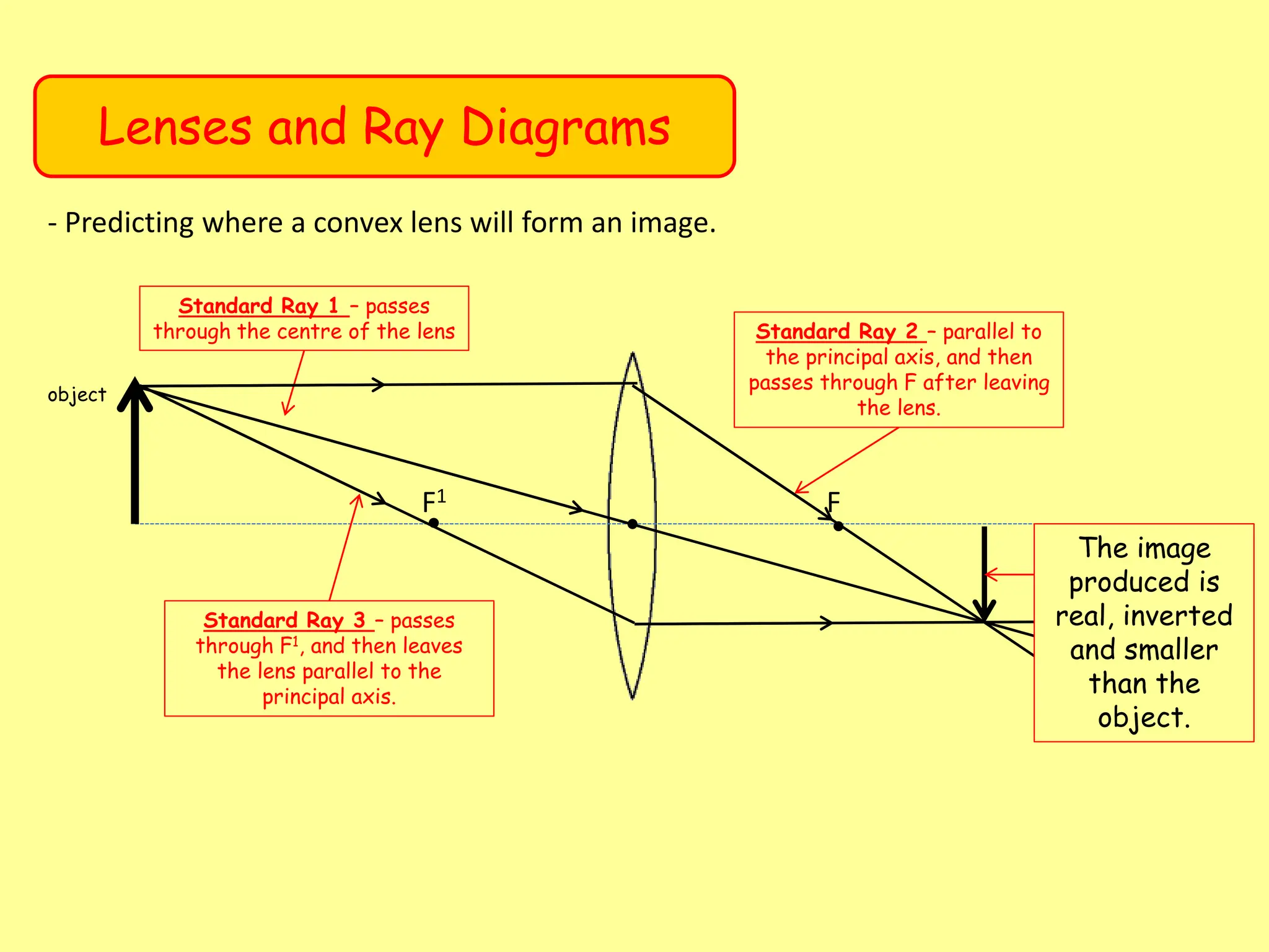
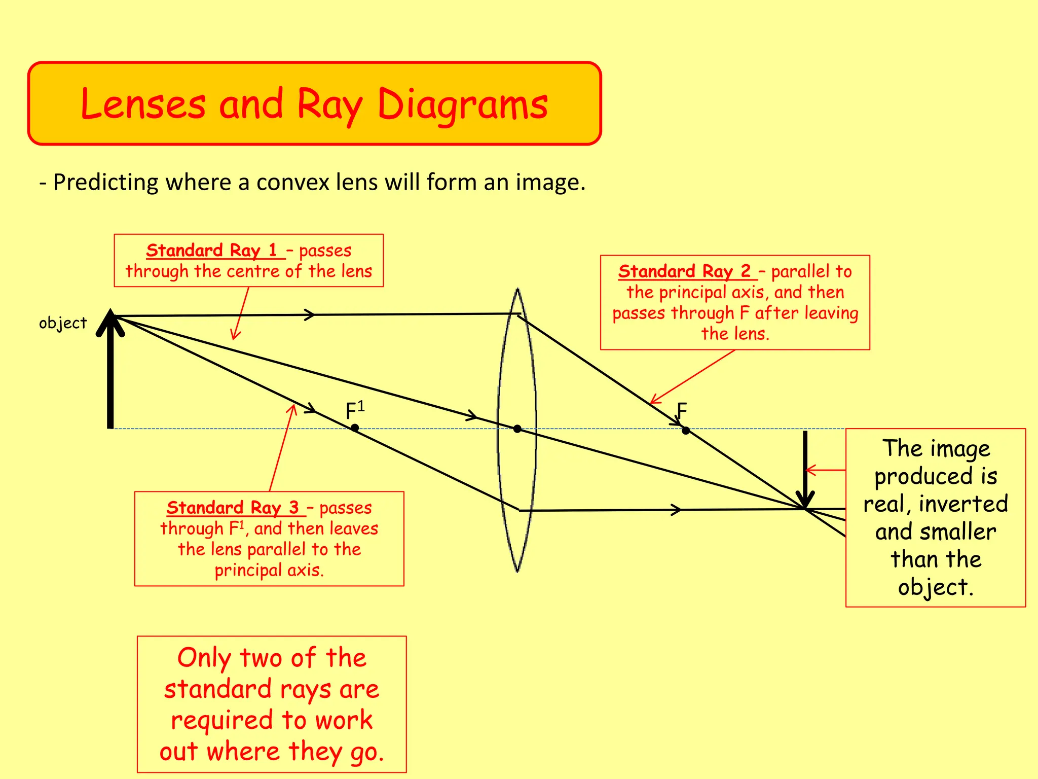
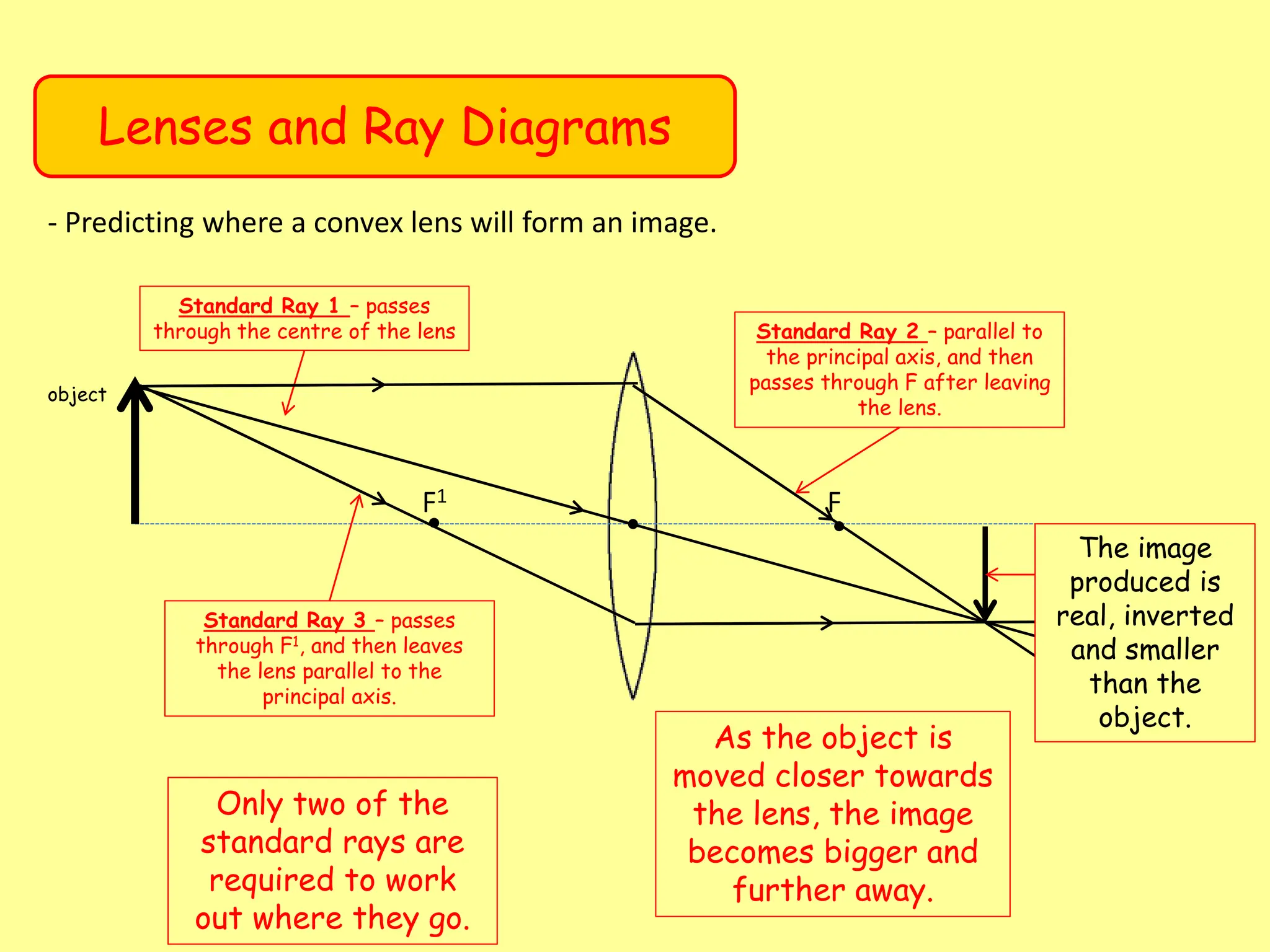
- Refraction of light through lenses and how this forms real, inverted images on the opposite side of the lens from the object.
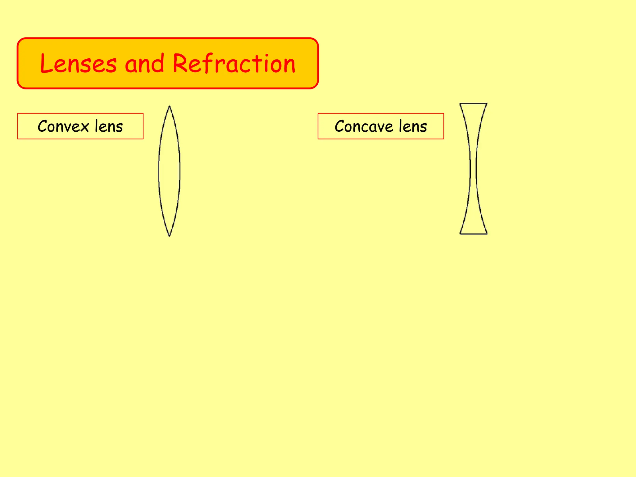
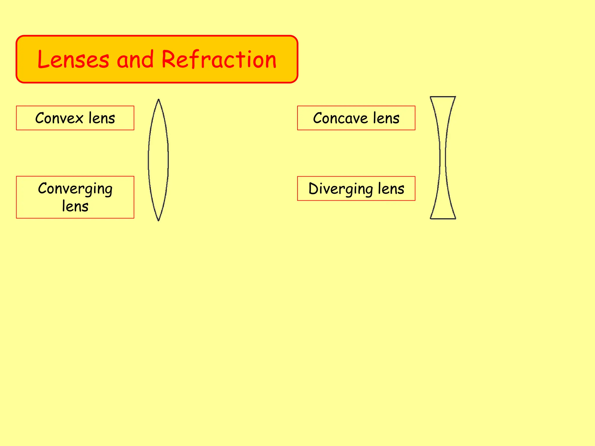
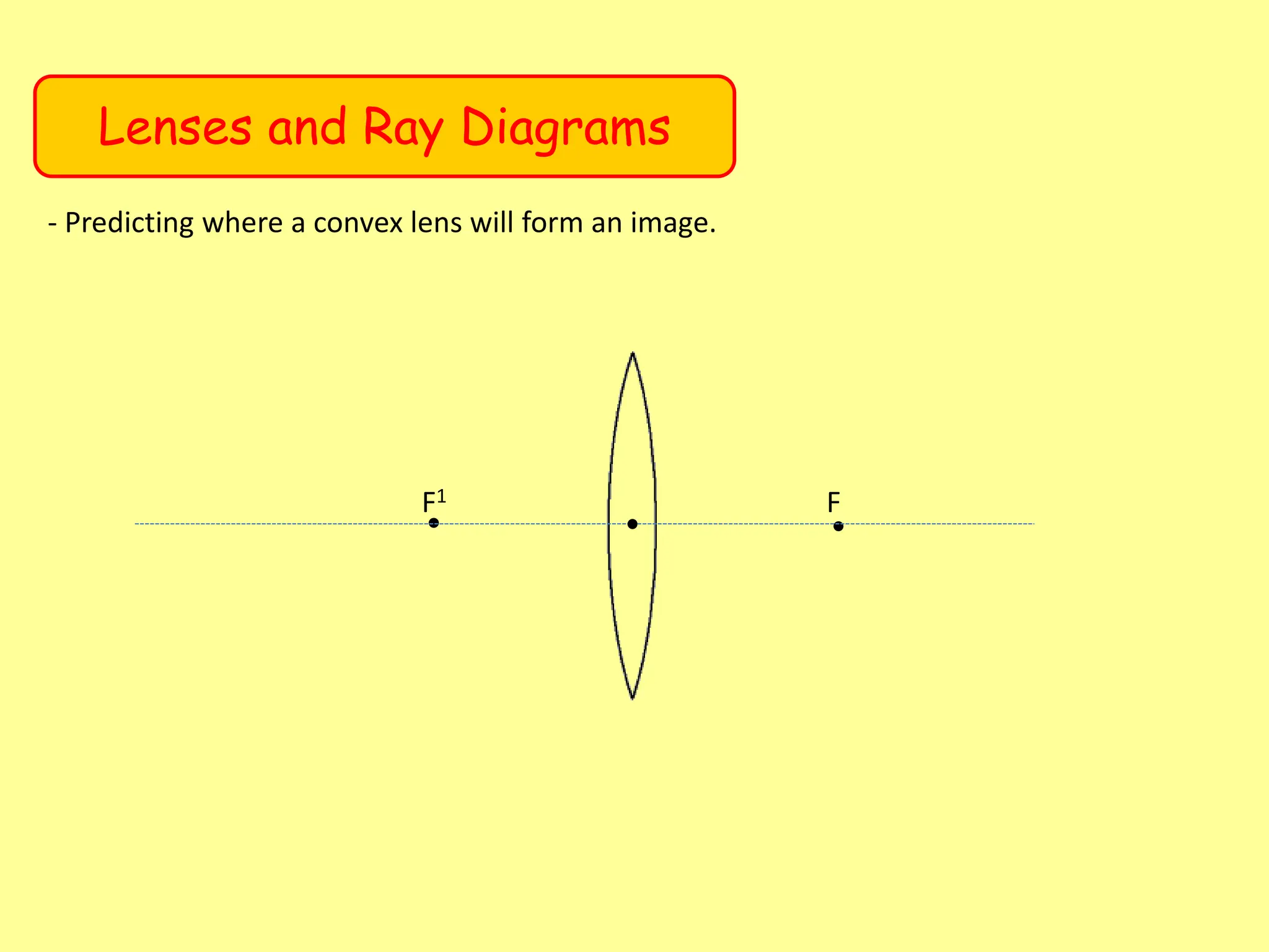
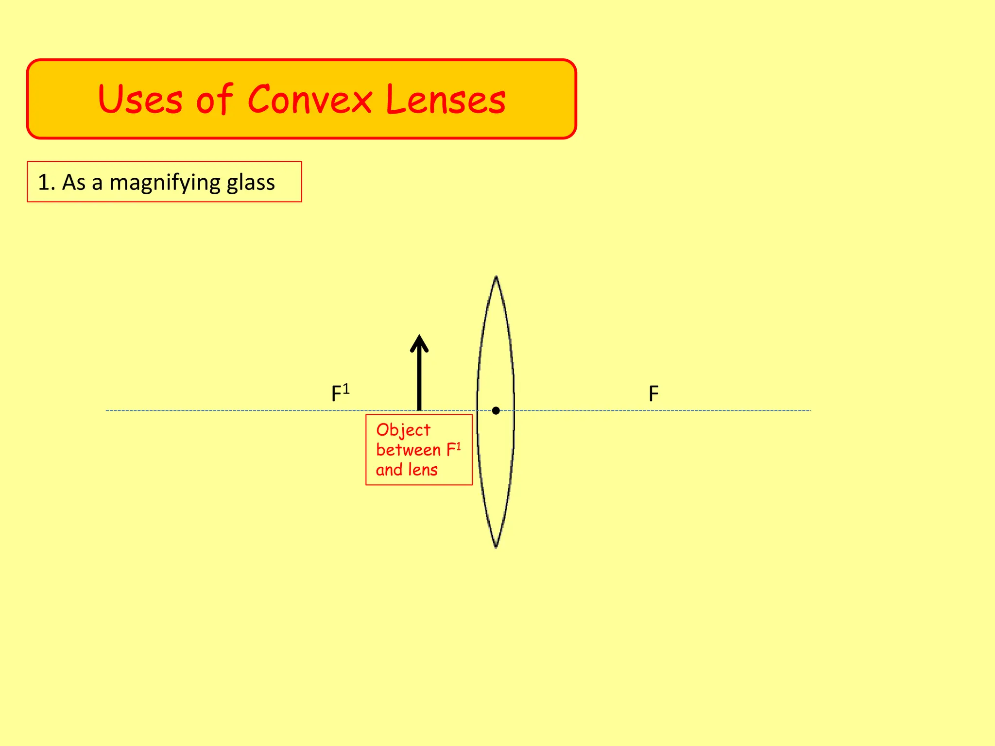
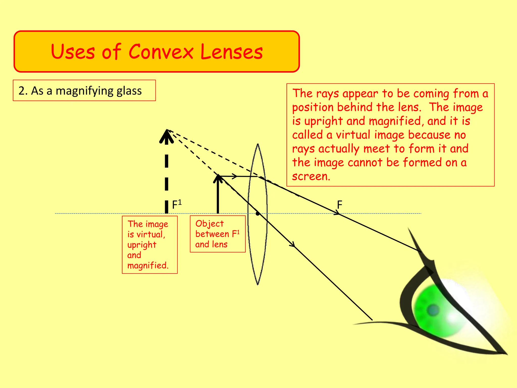
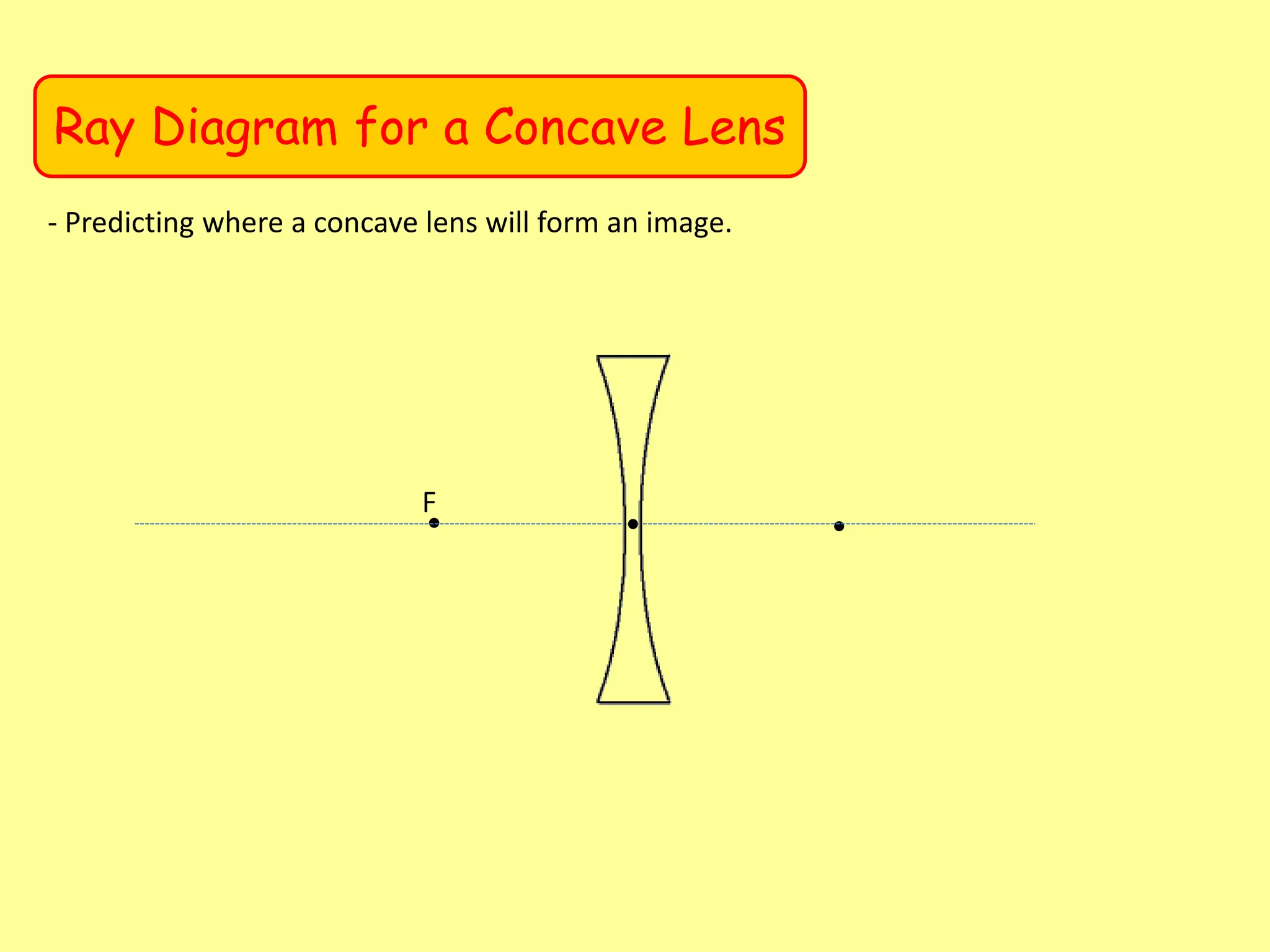
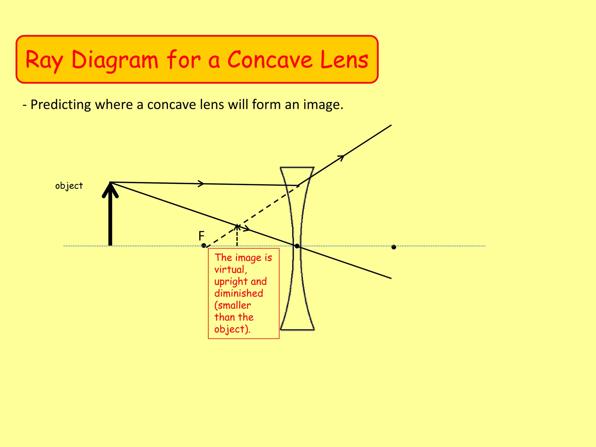
- Ray diagrams can be used to predict characteristics of images formed by convex and concave lenses, such as whether the image is real or virtual, upright or inverted, and magnified or diminished.
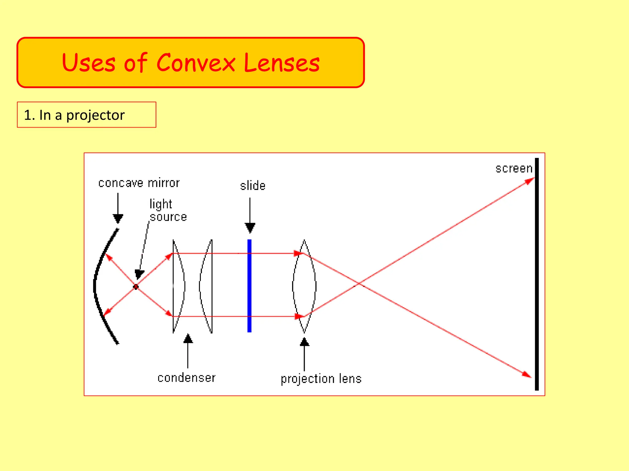
- Convex lenses are used in applications like magnifying glasses, projectors, and corrective eyeglasses.


![[Unit 12.2] refraction of light](https://cdn.slidesharecdn.com/ss_thumbnails/unit12-2refractionoflight-100829070254-phpapp01-thumbnail.jpg?width=640&height=640&fit=bounds)


