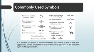
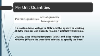
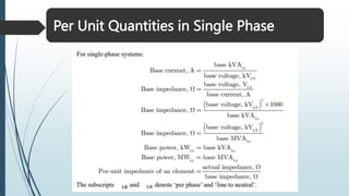
Power System Analysis
System Modeling
Single Line or One Line Diagram
The purpose of one-line diagram is to supply the significant information about the system in
concise form. The amount of information included on the diagram depends on the purpose for
which the diagram is intended.
Example:
The location of circuit breakers and relays is not important in making a load study. However,
information about the circuit breakers may be of extreme importance for determination of the
stability of a system under transient conditions resulting from a fault.
Rules:
1. Completed circuit through the neutral is omitted.
2. Component parts are indicated by standard symbols.
3. Circuit parameters are not shown.
4. A transmission line is represented by a single line between its two ends.
Commonly Used Symbols
If a resistor or reactor is inserted between the neutral of the Y and, the
appropriate symbol for resistance or inductance may be added to the standard
symbol of the grounded Y.
Two generators, one grounded through a reactor and one through a
resistor, are connected to a bus and through a step-up transformer to a
transmission line. Another generator, grounded through a reactor, is
connected to a bus and through a transformer to the opposite end of the
transmission line. A load is connected to each bus.
A Simple One Line Diagram
Impedance Diagram
Single-phase or per phase equivalent circuit, drawn from one-line
diagram, in order to calculate the performance of a system under load
conditions.
Reactance Diagram
Per Unit Quantities
If a system base voltage is 320V and the system is working
at 220V then per unit quantity (p.u.) is = 220/320 = 0.6875 p.u.
Usually, base megavoltamperes (MVA) and base voltage in
kilovolts (kV) are the quantities selected to specify the base.
Per Unit Quantities
Per Unit Quantities in Single Phase
Per Unit Quantities in Three Phase
Changing from One Base to Another
Sometimes p.u. impedance of a component is expressed on a base other than the one
selected as base for the part of the system in which the component is located. Resistance
and reactance of a device in percent or per unit are usually available from the manufacturer. The
impedance base is understood to be derived from the rated kVAs and kVs of the device.
All impedances in any one part of a system must be expressed on the same impedance base.
Per Unit Quantities
• Base kV and Base kVA/MVA are selected for a system: called system
base
• Base kV changes through out a system depending on
transformer turns ratio
• Base MVA does not change through out a system
• For any components: pu impedance or reactance is given with
respect to their own ratings / equipment base
• Hence base conversion is required to convert everything into a
common system base.
• In power systems: widely accepted base is 100 MVA unless otherwise
specified
Advantages of Per Unit Computations
Practice Problem
Practice Problem - 1
With transformer rated values as base quantities, express impedances in per unit. Working
with per unit values, determine the line to line voltage at the high voltage terminals of the
transformer and the sending end of the feeder.
The three-phase power and line to line ratings of the electric power system shown in Figure 1
are given below.
Draw an impedance diagram showing all impedances in per-unit on a 100-MVA base. Choose
20kV as the voltage base for generator.
Practice Problem - 1
Base MVA = 100MVA
Base Voltage for Generator = 20kV
Base Voltage on Low Voltage Side of T1 = 20 kV
Base Voltage on High Voltage Side of T1 = (20*200/20) = 200 kV
Base Voltage on High Voltage Side of T2 = 200 kV
Base Voltage on Low Voltage Side of T2 = (200*20/200) = 20 kV
For Generator  X = 0.09 *
100
60
= 0.15 pu
For T1  X = 0.1 *
100
50
= 0.2 pu
For T2  X = 0.1 *
100
50
= 0.2 pu
For Motor  X = 0.08 *
100
43.2
* (
182
202) = 0.2 pu
Base Impedance of Transmission Line  Zbase_line =
2002
100
= 400Ω
p.u. Impedance of Line Zline =
120+𝑗200
400
= 0.3 + j 0.5 p.u.
Practice Problem - 2
By selecting a common base of 100 MVA and 22 kV on the generator side, draw an
impedance diagram showing all impedances including the load impedance in per unit.
Practice Problem - 2
Generator side  Base voltage 22kV and Base Apparent Power 100MVA
Base Voltage at bus 1 is 22kV; this will be the base for the system. For the
other buses, convert using Transformer turns ratio.

Power-System-Slide-1.pptx

  • 1.
  • 2.
    Single Line orOne Line Diagram The purpose of one-line diagram is to supply the significant information about the system in concise form. The amount of information included on the diagram depends on the purpose for which the diagram is intended. Example: The location of circuit breakers and relays is not important in making a load study. However, information about the circuit breakers may be of extreme importance for determination of the stability of a system under transient conditions resulting from a fault. Rules: 1. Completed circuit through the neutral is omitted. 2. Component parts are indicated by standard symbols. 3. Circuit parameters are not shown. 4. A transmission line is represented by a single line between its two ends.
  • 3.
    Commonly Used Symbols Ifa resistor or reactor is inserted between the neutral of the Y and, the appropriate symbol for resistance or inductance may be added to the standard symbol of the grounded Y.
  • 4.
    Two generators, onegrounded through a reactor and one through a resistor, are connected to a bus and through a step-up transformer to a transmission line. Another generator, grounded through a reactor, is connected to a bus and through a transformer to the opposite end of the transmission line. A load is connected to each bus. A Simple One Line Diagram
  • 5.
    Impedance Diagram Single-phase orper phase equivalent circuit, drawn from one-line diagram, in order to calculate the performance of a system under load conditions.
  • 6.
  • 7.
    Per Unit Quantities Ifa system base voltage is 320V and the system is working at 220V then per unit quantity (p.u.) is = 220/320 = 0.6875 p.u. Usually, base megavoltamperes (MVA) and base voltage in kilovolts (kV) are the quantities selected to specify the base.
  • 8.
    Per Unit Quantities PerUnit Quantities in Single Phase
  • 9.
    Per Unit Quantitiesin Three Phase
  • 10.
    Changing from OneBase to Another Sometimes p.u. impedance of a component is expressed on a base other than the one selected as base for the part of the system in which the component is located. Resistance and reactance of a device in percent or per unit are usually available from the manufacturer. The impedance base is understood to be derived from the rated kVAs and kVs of the device. All impedances in any one part of a system must be expressed on the same impedance base.
  • 11.
    Per Unit Quantities •Base kV and Base kVA/MVA are selected for a system: called system base • Base kV changes through out a system depending on transformer turns ratio • Base MVA does not change through out a system • For any components: pu impedance or reactance is given with respect to their own ratings / equipment base • Hence base conversion is required to convert everything into a common system base. • In power systems: widely accepted base is 100 MVA unless otherwise specified
  • 12.
    Advantages of PerUnit Computations
  • 13.
    Practice Problem Practice Problem- 1 With transformer rated values as base quantities, express impedances in per unit. Working with per unit values, determine the line to line voltage at the high voltage terminals of the transformer and the sending end of the feeder. The three-phase power and line to line ratings of the electric power system shown in Figure 1 are given below. Draw an impedance diagram showing all impedances in per-unit on a 100-MVA base. Choose 20kV as the voltage base for generator.
  • 14.
    Practice Problem -1 Base MVA = 100MVA Base Voltage for Generator = 20kV Base Voltage on Low Voltage Side of T1 = 20 kV Base Voltage on High Voltage Side of T1 = (20*200/20) = 200 kV Base Voltage on High Voltage Side of T2 = 200 kV Base Voltage on Low Voltage Side of T2 = (200*20/200) = 20 kV For Generator  X = 0.09 * 100 60 = 0.15 pu For T1  X = 0.1 * 100 50 = 0.2 pu For T2  X = 0.1 * 100 50 = 0.2 pu For Motor  X = 0.08 * 100 43.2 * ( 182 202) = 0.2 pu Base Impedance of Transmission Line  Zbase_line = 2002 100 = 400Ω p.u. Impedance of Line Zline = 120+𝑗200 400 = 0.3 + j 0.5 p.u.
  • 15.
    Practice Problem -2 By selecting a common base of 100 MVA and 22 kV on the generator side, draw an impedance diagram showing all impedances including the load impedance in per unit.
  • 16.
    Practice Problem -2 Generator side  Base voltage 22kV and Base Apparent Power 100MVA Base Voltage at bus 1 is 22kV; this will be the base for the system. For the other buses, convert using Transformer turns ratio.