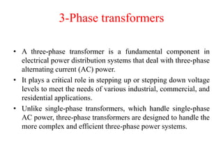
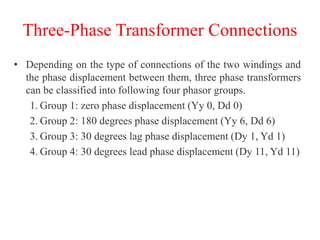
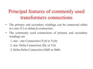
Electrical Machines
Subject code- EE 332
M1(Sec) - M3B1(Batch)
3-Phase transformers
• A three-phase transformer is a fundamental component in
electrical power distribution systems that deal with three-phase
alternating current (AC) power.
• It plays a critical role in stepping up or stepping down voltage
levels to meet the needs of various industrial, commercial, and
residential applications.
• Unlike single-phase transformers, which handle single-phase
AC power, three-phase transformers are designed to handle the
more complex and efficient three-phase power systems.
Fig. 1. Bank of three single phase transformers connected in star-delta connection
3-Phase transformers
Fig. 2. Three phase core type transformers
Fig. 3. Three phase shell type transformers
Three-Phase Transformer Connections
• Depending on the type of connections of the two windings and
the phase displacement between them, three phase transformers
can be classified into following four phasor groups.
1. Group 1: zero phase displacement (Yy 0, Dd 0)
2. Group 2: 180 degrees phase displacement (Yy 6, Dd 6)
3. Group 3: 30 degrees lag phase displacement (Dy 1, Yd 1)
4. Group 4: 30 degrees lead phase displacement (Dy 11, Yd 11)
Fig. 4. Connections of Y/y with zero phase displacement
Fig. 5. phasor diagrams of the circuits shown in Fig. 4.
Fig. 6. Connections of HV and LV in delta with zero phase displacement
Fig. 7. phasor diagrams of the circuits shown in Fig. 6.
Fig. 8. Y/y Connections with 180 degree phase displacement
Fig. 9. phasor diagrams of the circuits shown in Fig. 8.
Fig. 10. Connections of Dd 6 (with 180 degree phase displacement)
Fig. 11. 3-phase transformer connection, Dy 1 with 30 degree lag phase displacement
Fig. 12. Phase diagrams of Dy 1 connection, i.e. with 30 degree lag phase displacement
Fig. 13. Connections of 3-phase transformer, Dy11, i.e. 30 degree lead phase
displacement
Fig. 14. Phase diagrams of Dy 11 connection, i.e. with 30 degree lead phase displacement
Principal features of commonly used
transformers connections
• The primary and secondary windings can be connected either
in a star (Y) or delta(Δ) connection.
• The commonly used connections of primary and secondary
windings are
1. star - star Connection (Yy0 or Yy6)
2. star -Delta Connection (Dy or Yd)
3. Delta-Delta Connection (Dd0 or Dd6)
Star-Star
• Star-star connection is generally used for small, high-
voltage transformers. Because of star connection, number of
required turns/phase is reduced (as phase voltage in star
connection is 1/√3 times of line voltage only). Thus, the
amount of insulation required is also reduced.
• The ratio of line voltages on the primary side and the
secondary side is equal to the transformation ratio of the
transformers.
• Line voltages on both sides are in phase with each other.
• This connection can be used only if the connected load is
balanced
Star-Delta
• The primary winding is star star (Y) connected
with grounded neutral and the secondary winding
is delta connected.
• This connection is mainly used in step down
transformer at the substation end of the
transmission line.
• The ratio of secondary to primary line voltage is
1/√3 times the transformation ratio.
• There is 30° shift between the primary and
secondary line voltages.
Delta-Delta
• This connection is generally used for large, low-voltage
transformers. Number of required phase/turns is
relatively greater than that for star-star connection.
• The ratio of line voltages on the primary and the
secondary side is equal to the transformation ratio of
the transformers.
• This connection can be used even for unbalanced
loading.
• Another advantage of this type of connection is that
even if one transformer is disabled, system can
continue to operate in open delta connection but with
reduced available capacity.
Three phase to two phase conversion Scott
connection
• The Scott connection is a type of 3-phase to 2-phase transformer connection.
Fig. 15. Scott-connection
• One transformer is the main transformer, and the other is the
auxiliary transformer/teaser transformer.
• The main transformer has a center tap, which is connected
to the neutral point of the 3-phase system.
• The auxiliary transformer is tapped at 86.6% of its full
winding, which creates a 90-degree phase shift between its
primary and secondary windings.
• The primary windings of the two transformers are
connected in delta, and the secondary windings are
connected in star.
• The middle tap of the star winding is connected to the
neutral point of the 2-phase system.
• The two secondary windings of the Scott connection
produce two 2-phase voltages that are 90 degrees apart.
• The total power output of the Scott connection is equal to
the power input to the 3-phase system.
Fig. 16. Phasor diagram of scott-connected transformers
Fig. 17. Phasor diagrams under balanced loading at unity power factor
Behaviour under equal loading with unity
power factor
Fig. 18. Phasor diagram under balanced loading at 0.71 power factor lagging
Behaviour under equal loading at power factor
of 0.71 lagging
Fig. 19. Phasor diagram under unbalanced loading on secondary side
Behaviour under unequal loading with
different power factors
Parallel Operation of 3-Phase
Transformers
The conditions for proper parallel operation of two or more three
phase transformers are as follows.
i. The polarities and phase sequence must be same
ii. Identical primary and secondary terminal voltages
iii. The phase displacement between primary and secondary
voltages must be same for all the transformers
iv. The ratio of equivalent leakage reactance per phase to
equivalent resistance per phase should be same for all the
transformers to ensure that transformers operate at same
power factor and thus share active and reactive power
according to their ratings
v. Equal per unit ratings
25
• The following three phase transformers cane be operated in
parallel.
• However, transformers with +30 degrees phase displacement
may be operated in parallel with those having -30 degrees
phase displacement after reversing the phase sequence of
both the primary and secondary winding.
• If a number of transformers are worked in parallel taking
supply from a common source, there are some connections
which cannot be employed, that is
Transformer 1 Y/Y Y/Δ
Transformer 2 Δ/Δ Δ/Y
Transformer 1 Δ/Δ Y/Y
Transformer 2 Δ/Y Y/Δ
Parallel Operation of 3-Phase
Transform
Pros
Increased Capacity: Transformers
can collectively handle higher loads,
enhancing the system's overall
capacity.
Redundancy: If one transformer
fails, others can continue to provide
power, ensuring system reliability.
Efficient Load Distribution:
Transformers share the load based
on their impedance characteristics,
minimizing overloading of any
single unit.
Flexibility: Additional transformers
can be added to meet growing
demand without disrupting the
system
Cons
Complex Synchronization: Ensuring
proper synchronization and phase matching
is essential to prevent circulating currents
and voltage imbalances.
Voltage Regulation: Variations in
transformer parameters can lead to voltage
imbalances if not carefully managed.
Increased Maintenance: More
transformers mean more maintenance tasks,
which can increase operational costs.
Cost: Paralleling transformers requires
additional equipment and careful design,
which can result in higher initial costs.
26
Tap changing transformers
• Tap changing transformers are a type of power
transformer that includes a tap-changing
mechanism to adjust the turns ratio (voltage ratio)
between the primary and secondary windings.
• This feature allows for voltage regulation and
compensation in power distribution and
transmission systems.
Tap changing transformers(key features)
1. Voltage Regulation: Tap changing transformers are employed to regulate the
output voltage levels of a power transformer. By adjusting the number of turns on
either the primary or secondary winding, the voltage ratio can be altered to
compensate for variations in the supply voltage, load conditions, and line losses.
2. Load Variations: Tap changing transformers are particularly useful in scenarios
where the load on the power system varies widely. They can help maintain a more
consistent voltage level to meet the requirements of the connected equipment.
3. Tapping Mechanism: The tap-changing mechanism is a feature that allows for the
adjustment of the tap position on the transformer winding. This can be achieved
manually, through remote control, or automatically through a control system.
Common mechanisms include on-load tap changers (OLTC) and off-circuit tap
changers (OCTC).
4. On-Load Tap Changers (OLTC): These tap changers allow adjustments to be
made while the transformer is in operation. This is essential for maintaining a
continuous power supply during voltage adjustments. OLTCs use diverter switches
and selector switches to change the tap position.
5. Off-Circuit Tap Changers (OCTC): These tap changers require the transformer to
be disconnected from the load before changing the tap position. This method is less
common and is typically used in situations where the load can be temporarily
disconnected.
6. Automatic Voltage Regulation (AVR): Tap changing transformers equipped with
automatic control systems can regulate voltage levels without manual intervention.
Sensors and feedback mechanisms monitor the system's voltage and load conditions,
making necessary tap adjustments to maintain stable output voltage.
7. Voltage Boost and Buck: Tap changing transformers can raise or lower the output
voltage as needed. "Boosting" refers to increasing the output voltage above the nominal
value, while "bucking" involves reducing the output voltage.
8. Long-Distance Power Transmission: In long-distance power transmission, tap
changing transformers can help compensate for voltage drop along the transmission
lines, ensuring that the receiving end receives the required voltage.
9. Grid Stability: Tap changing transformers contribute to maintaining grid stability by
managing voltage fluctuations and preventing over- or under-voltage conditions.
10. Maintenance: Regular maintenance of tap changing mechanisms is important to
ensure their proper functioning and reliability. Cleaning, lubrication, and periodic testing
are essential.
11. Transformer Cooling: The tap changing mechanism can affect the cooling system
design of the transformer due to the space it occupies and potential heat generation
during tap changes.
12. Cost and Complexity: While tap changing transformers offer voltage regulation
benefits, they can be more complex and expensive compared to standard transformers
without tap-changing capabilities.
Tertiary winding
• In some high rating transformer, one winding in addition to its
primary and secondary winding is used.
• This additional winding, apart from primary and secondary
windings, is known as Tertiary winding of transformer.
• Because of this third winding, the transformer is called three
winding transformer or 3 winding transformer.
• Tertiary winding is provided in electrical power transformer to
meet one or more of the following requirements:
i. It reduces the unbalancing in the primary due to unbalancing in three phase
load.
ii. It redistributes the flow of fault current.
iii. Sometime it is required to supply an auxiliary load in different voltage level
in addition to its main secondary load. This secondary load can be taken
from tertiary winding of three winding transformer.
iv. As the tertiary winding is connected in delta formation in 3 winding
transformer, it assists in limitation of fault current in the event of a short
circuit from line to neutral.
Applications of 3-phase transformers
• Power transmission and distribution: 3-phase transformers are
used to transmit and distribute electrical power over long distances.
They are also used to step up or step down the voltage of electrical
power to meet the needs of different loads.
• Industrial applications: 3-phase transformers are used in a wide
variety of industrial applications, such as powering motors, lighting,
and other equipment. They are also used in power plants to convert
the alternating current (AC) produced by generators into a higher
voltage AC that can be transmitted over long distances.
• Commercial and residential applications: 3-phase transformers
are used in some commercial and residential buildings to provide
power for large loads, such as elevators, air conditioners, and
electric stoves. They are also used in some telecommunications
equipment.
• Railway locomotives: 3-phase transformers are used to
power the traction motors on railway locomotives.
• Electric vehicles: 3-phase transformers are used to convert
the DC power from the battery pack to the AC power
required by the electric motors.
• Wind turbines: 3-phase transformers are used to step up
the voltage of the AC power generated by wind turbines to a
level that can be transmitted over long distances.
• Solar power plants: 3-phase transformers are used to step
up the voltage of the DC power generated by solar panels to
a level that can be transmitted over long distances.
Thank you

3-phase trasnformers (1).pptx For electrical engineering

  • 1.
    Electrical Machines Subject code-EE 332 M1(Sec) - M3B1(Batch)
  • 2.
    3-Phase transformers • Athree-phase transformer is a fundamental component in electrical power distribution systems that deal with three-phase alternating current (AC) power. • It plays a critical role in stepping up or stepping down voltage levels to meet the needs of various industrial, commercial, and residential applications. • Unlike single-phase transformers, which handle single-phase AC power, three-phase transformers are designed to handle the more complex and efficient three-phase power systems.
  • 3.
    Fig. 1. Bankof three single phase transformers connected in star-delta connection 3-Phase transformers
  • 4.
    Fig. 2. Threephase core type transformers
  • 5.
    Fig. 3. Threephase shell type transformers
  • 6.
    Three-Phase Transformer Connections •Depending on the type of connections of the two windings and the phase displacement between them, three phase transformers can be classified into following four phasor groups. 1. Group 1: zero phase displacement (Yy 0, Dd 0) 2. Group 2: 180 degrees phase displacement (Yy 6, Dd 6) 3. Group 3: 30 degrees lag phase displacement (Dy 1, Yd 1) 4. Group 4: 30 degrees lead phase displacement (Dy 11, Yd 11)
  • 7.
    Fig. 4. Connectionsof Y/y with zero phase displacement Fig. 5. phasor diagrams of the circuits shown in Fig. 4.
  • 8.
    Fig. 6. Connectionsof HV and LV in delta with zero phase displacement Fig. 7. phasor diagrams of the circuits shown in Fig. 6.
  • 9.
    Fig. 8. Y/yConnections with 180 degree phase displacement Fig. 9. phasor diagrams of the circuits shown in Fig. 8.
  • 10.
    Fig. 10. Connectionsof Dd 6 (with 180 degree phase displacement)
  • 11.
    Fig. 11. 3-phasetransformer connection, Dy 1 with 30 degree lag phase displacement Fig. 12. Phase diagrams of Dy 1 connection, i.e. with 30 degree lag phase displacement
  • 12.
    Fig. 13. Connectionsof 3-phase transformer, Dy11, i.e. 30 degree lead phase displacement Fig. 14. Phase diagrams of Dy 11 connection, i.e. with 30 degree lead phase displacement
  • 13.
    Principal features ofcommonly used transformers connections • The primary and secondary windings can be connected either in a star (Y) or delta(Δ) connection. • The commonly used connections of primary and secondary windings are 1. star - star Connection (Yy0 or Yy6) 2. star -Delta Connection (Dy or Yd) 3. Delta-Delta Connection (Dd0 or Dd6)
  • 14.
    Star-Star • Star-star connectionis generally used for small, high- voltage transformers. Because of star connection, number of required turns/phase is reduced (as phase voltage in star connection is 1/√3 times of line voltage only). Thus, the amount of insulation required is also reduced. • The ratio of line voltages on the primary side and the secondary side is equal to the transformation ratio of the transformers. • Line voltages on both sides are in phase with each other. • This connection can be used only if the connected load is balanced
  • 15.
    Star-Delta • The primarywinding is star star (Y) connected with grounded neutral and the secondary winding is delta connected. • This connection is mainly used in step down transformer at the substation end of the transmission line. • The ratio of secondary to primary line voltage is 1/√3 times the transformation ratio. • There is 30° shift between the primary and secondary line voltages.
  • 16.
    Delta-Delta • This connectionis generally used for large, low-voltage transformers. Number of required phase/turns is relatively greater than that for star-star connection. • The ratio of line voltages on the primary and the secondary side is equal to the transformation ratio of the transformers. • This connection can be used even for unbalanced loading. • Another advantage of this type of connection is that even if one transformer is disabled, system can continue to operate in open delta connection but with reduced available capacity.
  • 17.
    Three phase totwo phase conversion Scott connection • The Scott connection is a type of 3-phase to 2-phase transformer connection. Fig. 15. Scott-connection
  • 18.
    • One transformeris the main transformer, and the other is the auxiliary transformer/teaser transformer. • The main transformer has a center tap, which is connected to the neutral point of the 3-phase system. • The auxiliary transformer is tapped at 86.6% of its full winding, which creates a 90-degree phase shift between its primary and secondary windings. • The primary windings of the two transformers are connected in delta, and the secondary windings are connected in star. • The middle tap of the star winding is connected to the neutral point of the 2-phase system. • The two secondary windings of the Scott connection produce two 2-phase voltages that are 90 degrees apart. • The total power output of the Scott connection is equal to the power input to the 3-phase system.
  • 19.
    Fig. 16. Phasordiagram of scott-connected transformers
  • 21.
    Fig. 17. Phasordiagrams under balanced loading at unity power factor Behaviour under equal loading with unity power factor
  • 22.
    Fig. 18. Phasordiagram under balanced loading at 0.71 power factor lagging Behaviour under equal loading at power factor of 0.71 lagging
  • 23.
    Fig. 19. Phasordiagram under unbalanced loading on secondary side Behaviour under unequal loading with different power factors
  • 24.
    Parallel Operation of3-Phase Transformers The conditions for proper parallel operation of two or more three phase transformers are as follows. i. The polarities and phase sequence must be same ii. Identical primary and secondary terminal voltages iii. The phase displacement between primary and secondary voltages must be same for all the transformers iv. The ratio of equivalent leakage reactance per phase to equivalent resistance per phase should be same for all the transformers to ensure that transformers operate at same power factor and thus share active and reactive power according to their ratings v. Equal per unit ratings
  • 25.
    25 • The followingthree phase transformers cane be operated in parallel. • However, transformers with +30 degrees phase displacement may be operated in parallel with those having -30 degrees phase displacement after reversing the phase sequence of both the primary and secondary winding. • If a number of transformers are worked in parallel taking supply from a common source, there are some connections which cannot be employed, that is Transformer 1 Y/Y Y/Δ Transformer 2 Δ/Δ Δ/Y Transformer 1 Δ/Δ Y/Y Transformer 2 Δ/Y Y/Δ
  • 26.
    Parallel Operation of3-Phase Transform Pros Increased Capacity: Transformers can collectively handle higher loads, enhancing the system's overall capacity. Redundancy: If one transformer fails, others can continue to provide power, ensuring system reliability. Efficient Load Distribution: Transformers share the load based on their impedance characteristics, minimizing overloading of any single unit. Flexibility: Additional transformers can be added to meet growing demand without disrupting the system Cons Complex Synchronization: Ensuring proper synchronization and phase matching is essential to prevent circulating currents and voltage imbalances. Voltage Regulation: Variations in transformer parameters can lead to voltage imbalances if not carefully managed. Increased Maintenance: More transformers mean more maintenance tasks, which can increase operational costs. Cost: Paralleling transformers requires additional equipment and careful design, which can result in higher initial costs. 26
  • 27.
    Tap changing transformers •Tap changing transformers are a type of power transformer that includes a tap-changing mechanism to adjust the turns ratio (voltage ratio) between the primary and secondary windings. • This feature allows for voltage regulation and compensation in power distribution and transmission systems.
  • 28.
    Tap changing transformers(keyfeatures) 1. Voltage Regulation: Tap changing transformers are employed to regulate the output voltage levels of a power transformer. By adjusting the number of turns on either the primary or secondary winding, the voltage ratio can be altered to compensate for variations in the supply voltage, load conditions, and line losses. 2. Load Variations: Tap changing transformers are particularly useful in scenarios where the load on the power system varies widely. They can help maintain a more consistent voltage level to meet the requirements of the connected equipment. 3. Tapping Mechanism: The tap-changing mechanism is a feature that allows for the adjustment of the tap position on the transformer winding. This can be achieved manually, through remote control, or automatically through a control system. Common mechanisms include on-load tap changers (OLTC) and off-circuit tap changers (OCTC). 4. On-Load Tap Changers (OLTC): These tap changers allow adjustments to be made while the transformer is in operation. This is essential for maintaining a continuous power supply during voltage adjustments. OLTCs use diverter switches and selector switches to change the tap position. 5. Off-Circuit Tap Changers (OCTC): These tap changers require the transformer to be disconnected from the load before changing the tap position. This method is less common and is typically used in situations where the load can be temporarily disconnected.
  • 29.
    6. Automatic VoltageRegulation (AVR): Tap changing transformers equipped with automatic control systems can regulate voltage levels without manual intervention. Sensors and feedback mechanisms monitor the system's voltage and load conditions, making necessary tap adjustments to maintain stable output voltage. 7. Voltage Boost and Buck: Tap changing transformers can raise or lower the output voltage as needed. "Boosting" refers to increasing the output voltage above the nominal value, while "bucking" involves reducing the output voltage. 8. Long-Distance Power Transmission: In long-distance power transmission, tap changing transformers can help compensate for voltage drop along the transmission lines, ensuring that the receiving end receives the required voltage. 9. Grid Stability: Tap changing transformers contribute to maintaining grid stability by managing voltage fluctuations and preventing over- or under-voltage conditions. 10. Maintenance: Regular maintenance of tap changing mechanisms is important to ensure their proper functioning and reliability. Cleaning, lubrication, and periodic testing are essential. 11. Transformer Cooling: The tap changing mechanism can affect the cooling system design of the transformer due to the space it occupies and potential heat generation during tap changes. 12. Cost and Complexity: While tap changing transformers offer voltage regulation benefits, they can be more complex and expensive compared to standard transformers without tap-changing capabilities.
  • 30.
    Tertiary winding • Insome high rating transformer, one winding in addition to its primary and secondary winding is used. • This additional winding, apart from primary and secondary windings, is known as Tertiary winding of transformer. • Because of this third winding, the transformer is called three winding transformer or 3 winding transformer. • Tertiary winding is provided in electrical power transformer to meet one or more of the following requirements: i. It reduces the unbalancing in the primary due to unbalancing in three phase load. ii. It redistributes the flow of fault current. iii. Sometime it is required to supply an auxiliary load in different voltage level in addition to its main secondary load. This secondary load can be taken from tertiary winding of three winding transformer. iv. As the tertiary winding is connected in delta formation in 3 winding transformer, it assists in limitation of fault current in the event of a short circuit from line to neutral.
  • 31.
    Applications of 3-phasetransformers • Power transmission and distribution: 3-phase transformers are used to transmit and distribute electrical power over long distances. They are also used to step up or step down the voltage of electrical power to meet the needs of different loads. • Industrial applications: 3-phase transformers are used in a wide variety of industrial applications, such as powering motors, lighting, and other equipment. They are also used in power plants to convert the alternating current (AC) produced by generators into a higher voltage AC that can be transmitted over long distances. • Commercial and residential applications: 3-phase transformers are used in some commercial and residential buildings to provide power for large loads, such as elevators, air conditioners, and electric stoves. They are also used in some telecommunications equipment.
  • 32.
    • Railway locomotives:3-phase transformers are used to power the traction motors on railway locomotives. • Electric vehicles: 3-phase transformers are used to convert the DC power from the battery pack to the AC power required by the electric motors. • Wind turbines: 3-phase transformers are used to step up the voltage of the AC power generated by wind turbines to a level that can be transmitted over long distances. • Solar power plants: 3-phase transformers are used to step up the voltage of the DC power generated by solar panels to a level that can be transmitted over long distances.
  • 33.