SlideShare a Scribd company logo
1 of 4
Unit 2:

    1. Compute the following in polar form:

          a. α2 -1 b. 1- α – α2 c. 3α2 +4α +2 d. jα

    2. Three identical resistors are star connected and rated 2500V, 750 kVA. This three-phase unit
       of resistors is connected to the Y side of a Δ-Y transformer. The following are the voltages at
       the resistor load: ΙVabΙ =2000V; ΙVbcΙ=2900V; ΙVcaΙ=2500V

          Choose base as 2500V, 750kVA and determine the line voltages and currents in per unit on
          the delta side of the transformer. It may be assumed that the load neutral is not connected
          to the neutral of the transformer secondary.

    3. Determine the symmetrical components of three voltages: Va = 200(0◦), Vb=200(245◦) and
       Vc=200(105◦) V

    4. A single phase resistive load of 100kVA is connected across the lines bc of a balanced supply
       of 3kV. Compute the symmetrical components of the line currents.

    5. A delta connected resistive load is connected across a balanced three-phase supply of 400V
       as shown in the figure. Find the symmetrical components of line currents and delta currents.


    6. Three resistances of 10, 15 and 20 ohms are connected in star across a three-phase supply of
       200V per phase as shown in the figure. The supply neutral is earthed while the load neutral
       is isolated. Find the currents in each load branch and the voltage of load neutral above
       earth. Use the method of symmetrical components.
7. The voltages at the terminals of a balanced load consisting of three 20 ohm Y-connected
   resistors are 200(0◦), 10(255.5◦) and 200(151◦) V. Find the line currents from the symmetrical
   components of the line voltages if the neutral of the load is isolated. What relation exists
   between the symmetrical components of the line and phase voltages? Find the power
   expended in three 20 ohm resistors from the symmetrical components of currents and
   voltages.

8. Draw the positive, negative and zero sequence impedence networks for the power system
   given in the figure. Choose a base of 50 MVA, 220kV in the 50Ω transmission lines and mark
   all impedences in pu. The ratings of the generators and transformers are:

    Generator 1: 25 MVA, 11kV, X”=20%

    Generator 2: 25 MVA, 11kV, X”=20%

    Three-phase transformer (each): 20MVA, 11 Y/220 Y kV, X=15% to its subtransient
    reactance. The zero sequence reactance of each machine is 8%. Assume that the zero
    sequence reactances of the lines are 250% of their positive sequence reactances.


9. For the power system in the figure draw the positive, negative and zero sequence networks.
   The generators and transformers are rated as follows:
Generator 1: 25 MVA, 11kVA, X”=0.2, X2=0.15, X0=0.03 pu

    Generator 2: 15 MVA, 11kVA, X”=0.2, X2=0.15, X0=0.05 pu

    Synchronous motor 3: 25MVA, 11kVA, X”=0.2, X2=0.2, X0=0.1 pu

    Transformer 1: 25MVA, 11 Δ/120 Y kV, X=10%

                 2: 12.5MVA, 11 Δ/120 Y kV, X=10%

                 3: 10MVA, 120 Y/11 Y kV, X=10%

    Choose a base of 50 MVA, 11kV in the circuit of generator 1.


    Note: Zero sequence reactance of each line is 250% of its positive sequence reactance.


10. Consider the circuit shown in the figure. Suppose Van=100(0◦), Vbn=60(60◦), Vcn=60(120◦),
    Xs=12Ω and Xab=Xbc=Xca=5Ω.

    a. Calculate Ia, Ib and Ic without using symmetrical components.

    b. Calculate Ia, Ib and Ic using symmetrical components.
Answers:

1. a. 1.732(210◦) b. 2(0◦) c. 1.732(150◦) d. 1(210◦)

2. Ia=j1.16 pu, Vab=1.17(109.5◦) pu, Vbc=0.953(-65.4◦) pu, Vcb=0.995(-113.1◦) pu

3. Va1=197.8(-3.3◦) V; Va2=20.2(158.1◦) V; Vao=21.61(10.63◦) V

4. Ia1=19.23(-30◦) A, Ia2=19.23(150◦) A; Iao=0A

5. IA1=27.87(-30◦ ) A; IA2=13(-44.93◦ ) A; IA0=0A

6. Ia=16.16+j1.335A, Ib=-9.24-j10.66A; Ic=-6.93+j9.32 A, VNn=Va0=40.75 V

7. 1500.2 W

More Related Content

What's hot

Power factor improvement
Power factor improvementPower factor improvement
Power factor improvementharshal567
 
importance of reactive power in power system
importance of reactive power in power systemimportance of reactive power in power system
importance of reactive power in power systemsneh pratap singh
 
WIDE AREA MONITORING SYSTEMS(WAMS)
WIDE AREA MONITORING SYSTEMS(WAMS)WIDE AREA MONITORING SYSTEMS(WAMS)
WIDE AREA MONITORING SYSTEMS(WAMS)Vikram Purohit
 
Economic dispatch in power systems - Question Bank
Economic dispatch in power systems - Question Bank  Economic dispatch in power systems - Question Bank
Economic dispatch in power systems - Question Bank Mathankumar S
 
Load dispatch center
Load dispatch centerLoad dispatch center
Load dispatch centerddxdharmesh
 
Harmonics: Causes and Effects
Harmonics: Causes and EffectsHarmonics: Causes and Effects
Harmonics: Causes and EffectsLeonardo ENERGY
 
Automatic load sharing of transformer using microcontroller
Automatic load sharing of transformer using microcontrollerAutomatic load sharing of transformer using microcontroller
Automatic load sharing of transformer using microcontrollerPrakhar Anand
 
Three phase semi converter
Three phase semi converterThree phase semi converter
Three phase semi converterArpit Raval
 
Series & shunt compensation and FACTs Devices
Series & shunt compensation and FACTs DevicesSeries & shunt compensation and FACTs Devices
Series & shunt compensation and FACTs Deviceskhemraj298
 
Harmonics in power system
Harmonics in power systemHarmonics in power system
Harmonics in power systemMinh Anh Nguyen
 
Instantaneous Reactive Power Theory And Its Applications
Instantaneous Reactive Power Theory And Its ApplicationsInstantaneous Reactive Power Theory And Its Applications
Instantaneous Reactive Power Theory And Its Applicationsarunj89
 
Capacitive voltage transformer (1)
Capacitive voltage transformer (1)Capacitive voltage transformer (1)
Capacitive voltage transformer (1)kaushal boghani
 
Hvdc transmission & its applications
Hvdc transmission & its applicationsHvdc transmission & its applications
Hvdc transmission & its applicationsPooja Dubey
 
Unit 4 Automatic Generation Control
Unit 4 Automatic Generation ControlUnit 4 Automatic Generation Control
Unit 4 Automatic Generation ControlSANTOSH GADEKAR
 
Three phase voltage source inverter
Three phase voltage source inverterThree phase voltage source inverter
Three phase voltage source invertertamilnesaner
 

What's hot (20)

Power factor improvement
Power factor improvementPower factor improvement
Power factor improvement
 
importance of reactive power in power system
importance of reactive power in power systemimportance of reactive power in power system
importance of reactive power in power system
 
WIDE AREA MONITORING SYSTEMS(WAMS)
WIDE AREA MONITORING SYSTEMS(WAMS)WIDE AREA MONITORING SYSTEMS(WAMS)
WIDE AREA MONITORING SYSTEMS(WAMS)
 
Economic dispatch in power systems - Question Bank
Economic dispatch in power systems - Question Bank  Economic dispatch in power systems - Question Bank
Economic dispatch in power systems - Question Bank
 
Load dispatch center
Load dispatch centerLoad dispatch center
Load dispatch center
 
Harmonics: Causes and Effects
Harmonics: Causes and EffectsHarmonics: Causes and Effects
Harmonics: Causes and Effects
 
Automatic load sharing of transformer using microcontroller
Automatic load sharing of transformer using microcontrollerAutomatic load sharing of transformer using microcontroller
Automatic load sharing of transformer using microcontroller
 
Three phase semi converter
Three phase semi converterThree phase semi converter
Three phase semi converter
 
Series & shunt compensation and FACTs Devices
Series & shunt compensation and FACTs DevicesSeries & shunt compensation and FACTs Devices
Series & shunt compensation and FACTs Devices
 
Harmonics in power system
Harmonics in power systemHarmonics in power system
Harmonics in power system
 
Instantaneous Reactive Power Theory And Its Applications
Instantaneous Reactive Power Theory And Its ApplicationsInstantaneous Reactive Power Theory And Its Applications
Instantaneous Reactive Power Theory And Its Applications
 
Structure of power system
Structure of power systemStructure of power system
Structure of power system
 
Capacitive voltage transformer (1)
Capacitive voltage transformer (1)Capacitive voltage transformer (1)
Capacitive voltage transformer (1)
 
Unit commitment
Unit commitmentUnit commitment
Unit commitment
 
Reactive power compensation
Reactive power compensationReactive power compensation
Reactive power compensation
 
Hvdc transmission & its applications
Hvdc transmission & its applicationsHvdc transmission & its applications
Hvdc transmission & its applications
 
132 33kv substation
132 33kv substation132 33kv substation
132 33kv substation
 
Unit 4 Automatic Generation Control
Unit 4 Automatic Generation ControlUnit 4 Automatic Generation Control
Unit 4 Automatic Generation Control
 
Power quality.ppt
Power quality.pptPower quality.ppt
Power quality.ppt
 
Three phase voltage source inverter
Three phase voltage source inverterThree phase voltage source inverter
Three phase voltage source inverter
 

Viewers also liked

Unit1 And 2 Sample Solutions
Unit1 And 2 Sample SolutionsUnit1 And 2 Sample Solutions
Unit1 And 2 Sample SolutionsAbha Tripathi
 
Unit 1, Power system Analysis
Unit 1, Power system AnalysisUnit 1, Power system Analysis
Unit 1, Power system AnalysisAbha Tripathi
 
Ee 1351 power system analysis
Ee 1351 power system analysisEe 1351 power system analysis
Ee 1351 power system analysisHari Kumar
 
Power System Analysis!
Power System Analysis!Power System Analysis!
Power System Analysis!PRABHAHARAN429
 
Questions practice unit iv
Questions practice unit ivQuestions practice unit iv
Questions practice unit ivAbha Tripathi
 
Unit 2 samplesolutions
Unit 2 samplesolutionsUnit 2 samplesolutions
Unit 2 samplesolutionsAbha Tripathi
 
Practice questions for unit ii
Practice questions for unit iiPractice questions for unit ii
Practice questions for unit iiAbha Tripathi
 
Step1 Single Line Diagram
Step1 Single Line DiagramStep1 Single Line Diagram
Step1 Single Line Diagramnanonon
 
TPs-TDs : Travaux Pratiques & Dérigés (version 2014-2017) Génie Electrique/Ex...
TPs-TDs : Travaux Pratiques & Dérigés (version 2014-2017) Génie Electrique/Ex...TPs-TDs : Travaux Pratiques & Dérigés (version 2014-2017) Génie Electrique/Ex...
TPs-TDs : Travaux Pratiques & Dérigés (version 2014-2017) Génie Electrique/Ex...Mohammed TAMALI
 
Power system analysis material -Mathankumar.s VMKVEC
Power system analysis material -Mathankumar.s  VMKVECPower system analysis material -Mathankumar.s  VMKVEC
Power system analysis material -Mathankumar.s VMKVECMathankumar S
 
Power system analysis (III-EEE)
Power system analysis  (III-EEE)Power system analysis  (III-EEE)
Power system analysis (III-EEE)betasam
 
Problemas resueltos cortocircuito trifasico
Problemas resueltos cortocircuito trifasicoProblemas resueltos cortocircuito trifasico
Problemas resueltos cortocircuito trifasicopaulelrapido
 

Viewers also liked (20)

Unit1 And 2 Sample Solutions
Unit1 And 2 Sample SolutionsUnit1 And 2 Sample Solutions
Unit1 And 2 Sample Solutions
 
Unit 1, Power system Analysis
Unit 1, Power system AnalysisUnit 1, Power system Analysis
Unit 1, Power system Analysis
 
Ee 1351 power system analysis
Ee 1351 power system analysisEe 1351 power system analysis
Ee 1351 power system analysis
 
Power System Analysis!
Power System Analysis!Power System Analysis!
Power System Analysis!
 
Questions practice unit iv
Questions practice unit ivQuestions practice unit iv
Questions practice unit iv
 
Questions unit4
Questions unit4Questions unit4
Questions unit4
 
Unit v
Unit vUnit v
Unit v
 
Unit4questions
Unit4questionsUnit4questions
Unit4questions
 
Unit1questions
Unit1questionsUnit1questions
Unit1questions
 
Unit 2 samplesolutions
Unit 2 samplesolutionsUnit 2 samplesolutions
Unit 2 samplesolutions
 
Practice questions for unit ii
Practice questions for unit iiPractice questions for unit ii
Practice questions for unit ii
 
Solutions -unit4
Solutions  -unit4Solutions  -unit4
Solutions -unit4
 
Practice questions
Practice questionsPractice questions
Practice questions
 
Unit1 8
Unit1 8Unit1 8
Unit1 8
 
Step1 Single Line Diagram
Step1 Single Line DiagramStep1 Single Line Diagram
Step1 Single Line Diagram
 
TPs-TDs : Travaux Pratiques & Dérigés (version 2014-2017) Génie Electrique/Ex...
TPs-TDs : Travaux Pratiques & Dérigés (version 2014-2017) Génie Electrique/Ex...TPs-TDs : Travaux Pratiques & Dérigés (version 2014-2017) Génie Electrique/Ex...
TPs-TDs : Travaux Pratiques & Dérigés (version 2014-2017) Génie Electrique/Ex...
 
Power system analysis material -Mathankumar.s VMKVEC
Power system analysis material -Mathankumar.s  VMKVECPower system analysis material -Mathankumar.s  VMKVEC
Power system analysis material -Mathankumar.s VMKVEC
 
Power system-analysis-psr murthy
Power system-analysis-psr murthyPower system-analysis-psr murthy
Power system-analysis-psr murthy
 
Power system analysis (III-EEE)
Power system analysis  (III-EEE)Power system analysis  (III-EEE)
Power system analysis (III-EEE)
 
Problemas resueltos cortocircuito trifasico
Problemas resueltos cortocircuito trifasicoProblemas resueltos cortocircuito trifasico
Problemas resueltos cortocircuito trifasico
 

Similar to Unit 2 Questions_Nagrath kothari

UNIT -I per unit calculation,EQUIVALENT CIRCUIT
UNIT -I per unit calculation,EQUIVALENT CIRCUITUNIT -I per unit calculation,EQUIVALENT CIRCUIT
UNIT -I per unit calculation,EQUIVALENT CIRCUITAbinaya Saraswathy T
 
BEF 23803 - Lecture 8 - Conservation of Complex Power.ppt
BEF 23803 - Lecture 8 - Conservation of Complex Power.pptBEF 23803 - Lecture 8 - Conservation of Complex Power.ppt
BEF 23803 - Lecture 8 - Conservation of Complex Power.pptLiewChiaPing
 
BEF 23803 - Lesson 3 - Balanced Delta Load Thre-Phase Systems.ppt
BEF 23803 - Lesson 3 - Balanced Delta Load Thre-Phase Systems.pptBEF 23803 - Lesson 3 - Balanced Delta Load Thre-Phase Systems.ppt
BEF 23803 - Lesson 3 - Balanced Delta Load Thre-Phase Systems.pptLiewChiaPing
 
Power-System-Slide-1.pptx
Power-System-Slide-1.pptxPower-System-Slide-1.pptx
Power-System-Slide-1.pptxssuser99d6551
 
dependent_sources.pdf
dependent_sources.pdfdependent_sources.pdf
dependent_sources.pdfSoniaJoshi25
 
Series and Parallel Circuits.ppt.pptx
Series and Parallel Circuits.ppt.pptxSeries and Parallel Circuits.ppt.pptx
Series and Parallel Circuits.ppt.pptxROLANDOMORALES28
 
Emec 1 bank nee 301
Emec 1 bank nee 301Emec 1 bank nee 301
Emec 1 bank nee 301Ravi Anand
 
Principles of Power Systems V.K Mehta Complete Book - Chapter 6
Principles of Power Systems V.K Mehta Complete Book - Chapter 6Principles of Power Systems V.K Mehta Complete Book - Chapter 6
Principles of Power Systems V.K Mehta Complete Book - Chapter 6Power System Operation
 
questions on diode analysis: Assignment6
questions on diode analysis: Assignment6questions on diode analysis: Assignment6
questions on diode analysis: Assignment6Akash Kumar Verma
 
Chapter20 powerpoint 090223020055-phpapp01
Chapter20 powerpoint 090223020055-phpapp01Chapter20 powerpoint 090223020055-phpapp01
Chapter20 powerpoint 090223020055-phpapp01Cleophas Rwemera
 
Chapter1 Questions
Chapter1 QuestionsChapter1 Questions
Chapter1 Questionsguest4ca222
 
Unit1 and 2 sample solutions
Unit1 and 2 sample solutionsUnit1 and 2 sample solutions
Unit1 and 2 sample solutionsAbha Tripathi
 
EE6501 Power System Analysis Rejinpaul_Important_Questions
EE6501 Power System Analysis Rejinpaul_Important_QuestionsEE6501 Power System Analysis Rejinpaul_Important_Questions
EE6501 Power System Analysis Rejinpaul_Important_QuestionsSanthosh Kumar
 
Term question eee 305
Term question eee 305Term question eee 305
Term question eee 305TamimAhmed43
 

Similar to Unit 2 Questions_Nagrath kothari (20)

E&e lab manual
E&e lab manualE&e lab manual
E&e lab manual
 
UNIT -I per unit calculation,EQUIVALENT CIRCUIT
UNIT -I per unit calculation,EQUIVALENT CIRCUITUNIT -I per unit calculation,EQUIVALENT CIRCUIT
UNIT -I per unit calculation,EQUIVALENT CIRCUIT
 
Questions unit3
Questions unit3Questions unit3
Questions unit3
 
BEF 23803 - Lecture 8 - Conservation of Complex Power.ppt
BEF 23803 - Lecture 8 - Conservation of Complex Power.pptBEF 23803 - Lecture 8 - Conservation of Complex Power.ppt
BEF 23803 - Lecture 8 - Conservation of Complex Power.ppt
 
BEF 23803 - Lesson 3 - Balanced Delta Load Thre-Phase Systems.ppt
BEF 23803 - Lesson 3 - Balanced Delta Load Thre-Phase Systems.pptBEF 23803 - Lesson 3 - Balanced Delta Load Thre-Phase Systems.ppt
BEF 23803 - Lesson 3 - Balanced Delta Load Thre-Phase Systems.ppt
 
Power-System-Slide-1.pptx
Power-System-Slide-1.pptxPower-System-Slide-1.pptx
Power-System-Slide-1.pptx
 
Pre engineering model question papers
Pre engineering model question papersPre engineering model question papers
Pre engineering model question papers
 
dependent_sources.pdf
dependent_sources.pdfdependent_sources.pdf
dependent_sources.pdf
 
Series and Parallel Circuits.ppt.pptx
Series and Parallel Circuits.ppt.pptxSeries and Parallel Circuits.ppt.pptx
Series and Parallel Circuits.ppt.pptx
 
Emec 1 bank nee 301
Emec 1 bank nee 301Emec 1 bank nee 301
Emec 1 bank nee 301
 
Principles of Power Systems V.K Mehta Complete Book - Chapter 6
Principles of Power Systems V.K Mehta Complete Book - Chapter 6Principles of Power Systems V.K Mehta Complete Book - Chapter 6
Principles of Power Systems V.K Mehta Complete Book - Chapter 6
 
Lecture 8
Lecture 8Lecture 8
Lecture 8
 
questions on diode analysis: Assignment6
questions on diode analysis: Assignment6questions on diode analysis: Assignment6
questions on diode analysis: Assignment6
 
Chapter20 powerpoint 090223020055-phpapp01
Chapter20 powerpoint 090223020055-phpapp01Chapter20 powerpoint 090223020055-phpapp01
Chapter20 powerpoint 090223020055-phpapp01
 
Chapter1 Questions
Chapter1 QuestionsChapter1 Questions
Chapter1 Questions
 
Unit1 and 2 sample solutions
Unit1 and 2 sample solutionsUnit1 and 2 sample solutions
Unit1 and 2 sample solutions
 
Lecture 2.pptx
Lecture 2.pptxLecture 2.pptx
Lecture 2.pptx
 
EE6501 Power System Analysis Rejinpaul_Important_Questions
EE6501 Power System Analysis Rejinpaul_Important_QuestionsEE6501 Power System Analysis Rejinpaul_Important_Questions
EE6501 Power System Analysis Rejinpaul_Important_Questions
 
Term question eee 305
Term question eee 305Term question eee 305
Term question eee 305
 
Ohmslawweb
OhmslawwebOhmslawweb
Ohmslawweb
 

More from Abha Tripathi

Power system Stability, Equal area criteria
Power system Stability, Equal area criteriaPower system Stability, Equal area criteria
Power system Stability, Equal area criteriaAbha Tripathi
 
Non Conventional (Renewable) Energy Sources 01
Non Conventional (Renewable) Energy Sources 01Non Conventional (Renewable) Energy Sources 01
Non Conventional (Renewable) Energy Sources 01Abha Tripathi
 
Conventional sources of energy (power generation) 01
Conventional sources of energy (power generation) 01Conventional sources of energy (power generation) 01
Conventional sources of energy (power generation) 01Abha Tripathi
 
Symmetrical components
Symmetrical componentsSymmetrical components
Symmetrical componentsAbha Tripathi
 
Representation of power system components
Representation of power system componentsRepresentation of power system components
Representation of power system componentsAbha Tripathi
 
Gas and diesel Plant
Gas and diesel PlantGas and diesel Plant
Gas and diesel PlantAbha Tripathi
 
NPP, Nuclear Power Plant,
NPP, Nuclear Power Plant, NPP, Nuclear Power Plant,
NPP, Nuclear Power Plant, Abha Tripathi
 
Questions From 1st Unit Nagrath
Questions From 1st Unit NagrathQuestions From 1st Unit Nagrath
Questions From 1st Unit NagrathAbha Tripathi
 
Grading The Insulator Problem
Grading The Insulator ProblemGrading The Insulator Problem
Grading The Insulator ProblemAbha Tripathi
 

More from Abha Tripathi (17)

Power system Stability, Equal area criteria
Power system Stability, Equal area criteriaPower system Stability, Equal area criteria
Power system Stability, Equal area criteria
 
Non Conventional (Renewable) Energy Sources 01
Non Conventional (Renewable) Energy Sources 01Non Conventional (Renewable) Energy Sources 01
Non Conventional (Renewable) Energy Sources 01
 
Conventional sources of energy (power generation) 01
Conventional sources of energy (power generation) 01Conventional sources of energy (power generation) 01
Conventional sources of energy (power generation) 01
 
Symmetrical components
Symmetrical componentsSymmetrical components
Symmetrical components
 
Representation of power system components
Representation of power system componentsRepresentation of power system components
Representation of power system components
 
Questions unit2 ch3
Questions unit2 ch3Questions unit2 ch3
Questions unit2 ch3
 
Renewable Sor
Renewable SorRenewable Sor
Renewable Sor
 
Gas and diesel Plant
Gas and diesel PlantGas and diesel Plant
Gas and diesel Plant
 
NPP, Nuclear Power Plant,
NPP, Nuclear Power Plant, NPP, Nuclear Power Plant,
NPP, Nuclear Power Plant,
 
Hydro E
Hydro EHydro E
Hydro E
 
Thermal power plant
Thermal power plantThermal power plant
Thermal power plant
 
Soln unit5
Soln unit5Soln unit5
Soln unit5
 
Questions From 1st Unit Nagrath
Questions From 1st Unit NagrathQuestions From 1st Unit Nagrath
Questions From 1st Unit Nagrath
 
Unit 3 Part 1
Unit 3 Part 1Unit 3 Part 1
Unit 3 Part 1
 
Grading The Insulator Problem
Grading The Insulator ProblemGrading The Insulator Problem
Grading The Insulator Problem
 
Dc Distribution
Dc DistributionDc Distribution
Dc Distribution
 
Dc Distributed Load
Dc Distributed LoadDc Distributed Load
Dc Distributed Load
 

Unit 2 Questions_Nagrath kothari

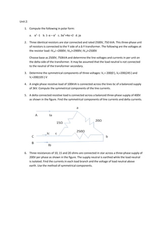
  • 1. Unit 2: 1. Compute the following in polar form: a. α2 -1 b. 1- α – α2 c. 3α2 +4α +2 d. jα 2. Three identical resistors are star connected and rated 2500V, 750 kVA. This three-phase unit of resistors is connected to the Y side of a Δ-Y transformer. The following are the voltages at the resistor load: ΙVabΙ =2000V; ΙVbcΙ=2900V; ΙVcaΙ=2500V Choose base as 2500V, 750kVA and determine the line voltages and currents in per unit on the delta side of the transformer. It may be assumed that the load neutral is not connected to the neutral of the transformer secondary. 3. Determine the symmetrical components of three voltages: Va = 200(0◦), Vb=200(245◦) and Vc=200(105◦) V 4. A single phase resistive load of 100kVA is connected across the lines bc of a balanced supply of 3kV. Compute the symmetrical components of the line currents. 5. A delta connected resistive load is connected across a balanced three-phase supply of 400V as shown in the figure. Find the symmetrical components of line currents and delta currents. 6. Three resistances of 10, 15 and 20 ohms are connected in star across a three-phase supply of 200V per phase as shown in the figure. The supply neutral is earthed while the load neutral is isolated. Find the currents in each load branch and the voltage of load neutral above earth. Use the method of symmetrical components.
  • 2. 7. The voltages at the terminals of a balanced load consisting of three 20 ohm Y-connected resistors are 200(0◦), 10(255.5◦) and 200(151◦) V. Find the line currents from the symmetrical components of the line voltages if the neutral of the load is isolated. What relation exists between the symmetrical components of the line and phase voltages? Find the power expended in three 20 ohm resistors from the symmetrical components of currents and voltages. 8. Draw the positive, negative and zero sequence impedence networks for the power system given in the figure. Choose a base of 50 MVA, 220kV in the 50Ω transmission lines and mark all impedences in pu. The ratings of the generators and transformers are: Generator 1: 25 MVA, 11kV, X”=20% Generator 2: 25 MVA, 11kV, X”=20% Three-phase transformer (each): 20MVA, 11 Y/220 Y kV, X=15% to its subtransient reactance. The zero sequence reactance of each machine is 8%. Assume that the zero sequence reactances of the lines are 250% of their positive sequence reactances. 9. For the power system in the figure draw the positive, negative and zero sequence networks. The generators and transformers are rated as follows:
  • 3. Generator 1: 25 MVA, 11kVA, X”=0.2, X2=0.15, X0=0.03 pu Generator 2: 15 MVA, 11kVA, X”=0.2, X2=0.15, X0=0.05 pu Synchronous motor 3: 25MVA, 11kVA, X”=0.2, X2=0.2, X0=0.1 pu Transformer 1: 25MVA, 11 Δ/120 Y kV, X=10% 2: 12.5MVA, 11 Δ/120 Y kV, X=10% 3: 10MVA, 120 Y/11 Y kV, X=10% Choose a base of 50 MVA, 11kV in the circuit of generator 1. Note: Zero sequence reactance of each line is 250% of its positive sequence reactance. 10. Consider the circuit shown in the figure. Suppose Van=100(0◦), Vbn=60(60◦), Vcn=60(120◦), Xs=12Ω and Xab=Xbc=Xca=5Ω. a. Calculate Ia, Ib and Ic without using symmetrical components. b. Calculate Ia, Ib and Ic using symmetrical components.
  • 4. Answers: 1. a. 1.732(210◦) b. 2(0◦) c. 1.732(150◦) d. 1(210◦) 2. Ia=j1.16 pu, Vab=1.17(109.5◦) pu, Vbc=0.953(-65.4◦) pu, Vcb=0.995(-113.1◦) pu 3. Va1=197.8(-3.3◦) V; Va2=20.2(158.1◦) V; Vao=21.61(10.63◦) V 4. Ia1=19.23(-30◦) A, Ia2=19.23(150◦) A; Iao=0A 5. IA1=27.87(-30◦ ) A; IA2=13(-44.93◦ ) A; IA0=0A 6. Ia=16.16+j1.335A, Ib=-9.24-j10.66A; Ic=-6.93+j9.32 A, VNn=Va0=40.75 V 7. 1500.2 W