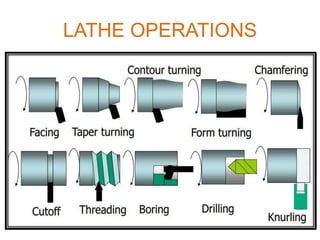
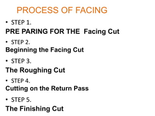
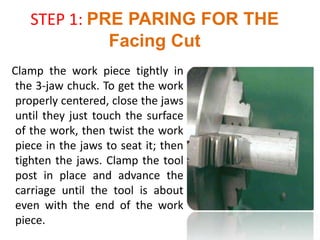
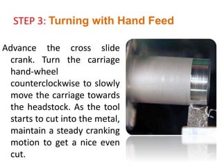
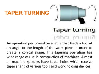
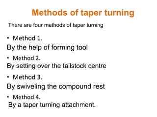
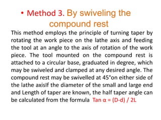
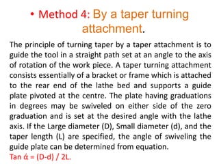
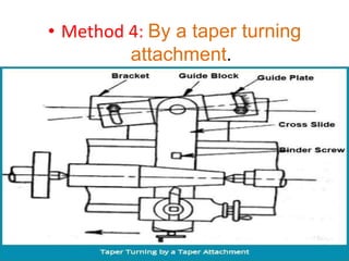
The document discusses various lathe operations including facing, turning, drilling, and taper turning. It provides step-by-step explanations of the processes with diagrams. Facing involves removing metal from the end of a workpiece to create a flat surface. Turning reduces the diameter of a rotating cylindrical workpiece. Drilling uses the lathe to drill holes before other internal operations. Taper turning creates a conical shape through various methods such as using a forming tool, setting over the tailstock, swiveling the compound rest, or a taper turning attachment.
A clear view on Shaping , slotting and planning machines kinematic scheme and their principal parts and difference between planning and shaping machine
Lathe-Types, Parts, Feed Mechanisms, Specifications,Lathe Accessories and Att...rajguptanitw
Who could ever think of manufacturing metals and other materials like wood and plastic without the lathe machine? Since the lathe machine is an important tool used in the machining process, which is an integral process in the manufacturing technology, it is just fitting to learn about it.
Machining is one of the most important material removal methods in the technology of manufacturing. It is basically a collection of material working processes that involves other processes such as drilling, shaping, sawing, planning, reaming, and grinding among others. Machining is practically a part of the manufacture of all metals and other materials such as plastics, and wood as well. An important machine that is useful in machining is the lathe machine.
A lathe machine is generally used in metalworking, metal spinning, woodturning, and glassworking. The various operations that it can perform include the following: sanding, cutting, knurling, drilling, and deforming of tools that are employed in creating objects which have symmetry about the axis of rotation. Some of the most common products of the lathe machine are crankshafts, camshafts, table legs, bowls, and candlestick holders.
The first lathe machine that was ever developed was the two-person lathe machine which was designed by the Egyptians in about 1300 BC. Primarily, there are two things that are achieved in this lathe machine set-up. The first is the turning of the wood working piece manually by a rope; and the second is the cutting of shapes in the wood by the use of a sharp tool. As civilizations progressed, there have been constant modifications and improvements over the original two-person lathe machine, most importantly on the production of the rotary motion.
The production of the rotary motion therefore evolved according to the following procedures: the Egyptians manual turning by hand; the Romans addition of a turning bow; the introduction of the pedal in the Middle Ages; the use of the steam engines during the Industrial Revolution; the employment of individual electric motors in the 19th and mid 20th centuries; and the latest of which is the adaption of numerically controlled mechanisms in controlling the lathe machine.
For the lathe machine to function and perform its operations, various important parts are integrated together. These essentials parts make up the lathe machine.
Whole lathe machine in brief which any one can understand easily and quickly.
A Perfect ppt to get knowledge about lathe machine, its parts, operations etc.
The given presentation consists of introduction to lathe machines, working principles, classification, constructions, accessories, lathe operations, work holding devices, etc
CNC machine parts is that it allows parts to be created quickly and easily much quicker than if the craftsman did everything by hand. Instead most workshops use Computer Numerical Control machines to produce generic parts or intricate parts of a product which won't be seen by the customer once the completed item is produced.
Centre lathe, constructional features, various operations and specifications, taper turning methods, thread cutting methods, special attachments, machining time and power estimation. Capstan and turret lathes – Automatic lathe: single spindle, swiss type, screw type, multi spindle - Turret Indexing mechanism - Bar feed mechanism
Centre lathe, constructional features, specification, operations – taper turning methods, thread cutting methods, special attachments, machining time and power estimation. Capstan and turret lathes- tool layout – automatic lathes: semi automatic – single spindle : Swiss type, automatic screw type – multi spindle:
Lathe taper turning and facing operation. In this presentation you will be able to see two basic operations done in a lathe,their purpose and their working procedure and also about what is lathe , its parts and some operation as well.
Final project report on grocery store management system..pdfKamal Acharya
In today’s fast-changing business environment, it’s extremely important to be able to respond to client needs in the most effective and timely manner. If your customers wish to see your business online and have instant access to your products or services.
Online Grocery Store is an e-commerce website, which retails various grocery products. This project allows viewing various products available enables registered users to purchase desired products instantly using Paytm, UPI payment processor (Instant Pay) and also can place order by using Cash on Delivery (Pay Later) option. This project provides an easy access to Administrators and Managers to view orders placed using Pay Later and Instant Pay options.
In order to develop an e-commerce website, a number of Technologies must be studied and understood. These include multi-tiered architecture, server and client-side scripting techniques, implementation technologies, programming language (such as PHP, HTML, CSS, JavaScript) and MySQL relational databases. This is a project with the objective to develop a basic website where a consumer is provided with a shopping cart website and also to know about the technologies used to develop such a website.
This document will discuss each of the underlying technologies to create and implement an e- commerce website.
Event Management System Vb Net Project Report.pdfKamal Acharya
In present era, the scopes of information technology growing with a very fast .We do not see any are untouched from this industry. The scope of information technology has become wider includes: Business and industry. Household Business, Communication, Education, Entertainment, Science, Medicine, Engineering, Distance Learning, Weather Forecasting. Carrier Searching and so on.
My project named “Event Management System” is software that store and maintained all events coordinated in college. It also helpful to print related reports. My project will help to record the events coordinated by faculties with their Name, Event subject, date & details in an efficient & effective ways.
In my system we have to make a system by which a user can record all events coordinated by a particular faculty. In our proposed system some more featured are added which differs it from the existing system such as security.
Quality defects in TMT Bars, Possible causes and Potential Solutions.PrashantGoswami42
Maintaining high-quality standards in the production of TMT bars is crucial for ensuring structural integrity in construction. Addressing common defects through careful monitoring, standardized processes, and advanced technology can significantly improve the quality of TMT bars. Continuous training and adherence to quality control measures will also play a pivotal role in minimizing these defects.
Forklift Classes Overview by Intella PartsIntella Parts
Discover the different forklift classes and their specific applications. Learn how to choose the right forklift for your needs to ensure safety, efficiency, and compliance in your operations.
For more technical information, visit our website https://intellaparts.com
Student information management system project report ii.pdfKamal Acharya
Our project explains about the student management. This project mainly explains the various actions related to student details. This project shows some ease in adding, editing and deleting the student details. It also provides a less time consuming process for viewing, adding, editing and deleting the marks of the students.
Democratizing Fuzzing at Scale by Abhishek Aryaabh.arya
Presented at NUS: Fuzzing and Software Security Summer School 2024
This keynote talks about the democratization of fuzzing at scale, highlighting the collaboration between open source communities, academia, and industry to advance the field of fuzzing. It delves into the history of fuzzing, the development of scalable fuzzing platforms, and the empowerment of community-driven research. The talk will further discuss recent advancements leveraging AI/ML and offer insights into the future evolution of the fuzzing landscape.
Hybrid optimization of pumped hydro system and solar- Engr. Abdul-Azeez.pdffxintegritypublishin
Advancements in technology unveil a myriad of electrical and electronic breakthroughs geared towards efficiently harnessing limited resources to meet human energy demands. The optimization of hybrid solar PV panels and pumped hydro energy supply systems plays a pivotal role in utilizing natural resources effectively. This initiative not only benefits humanity but also fosters environmental sustainability. The study investigated the design optimization of these hybrid systems, focusing on understanding solar radiation patterns, identifying geographical influences on solar radiation, formulating a mathematical model for system optimization, and determining the optimal configuration of PV panels and pumped hydro storage. Through a comparative analysis approach and eight weeks of data collection, the study addressed key research questions related to solar radiation patterns and optimal system design. The findings highlighted regions with heightened solar radiation levels, showcasing substantial potential for power generation and emphasizing the system's efficiency. Optimizing system design significantly boosted power generation, promoted renewable energy utilization, and enhanced energy storage capacity. The study underscored the benefits of optimizing hybrid solar PV panels and pumped hydro energy supply systems for sustainable energy usage. Optimizing the design of solar PV panels and pumped hydro energy supply systems as examined across diverse climatic conditions in a developing country, not only enhances power generation but also improves the integration of renewable energy sources and boosts energy storage capacities, particularly beneficial for less economically prosperous regions. Additionally, the study provides valuable insights for advancing energy research in economically viable areas. Recommendations included conducting site-specific assessments, utilizing advanced modeling tools, implementing regular maintenance protocols, and enhancing communication among system components.
NO1 Uk best vashikaran specialist in delhi vashikaran baba near me online vas...Amil Baba Dawood bangali
Contact with Dawood Bhai Just call on +92322-6382012 and we'll help you. We'll solve all your problems within 12 to 24 hours and with 101% guarantee and with astrology systematic. If you want to take any personal or professional advice then also you can call us on +92322-6382012 , ONLINE LOVE PROBLEM & Other all types of Daily Life Problem's.Then CALL or WHATSAPP us on +92322-6382012 and Get all these problems solutions here by Amil Baba DAWOOD BANGALI
#vashikaranspecialist #astrologer #palmistry #amliyaat #taweez #manpasandshadi #horoscope #spiritual #lovelife #lovespell #marriagespell#aamilbabainpakistan #amilbabainkarachi #powerfullblackmagicspell #kalajadumantarspecialist #realamilbaba #AmilbabainPakistan #astrologerincanada #astrologerindubai #lovespellsmaster #kalajaduspecialist #lovespellsthatwork #aamilbabainlahore#blackmagicformarriage #aamilbaba #kalajadu #kalailam #taweez #wazifaexpert #jadumantar #vashikaranspecialist #astrologer #palmistry #amliyaat #taweez #manpasandshadi #horoscope #spiritual #lovelife #lovespell #marriagespell#aamilbabainpakistan #amilbabainkarachi #powerfullblackmagicspell #kalajadumantarspecialist #realamilbaba #AmilbabainPakistan #astrologerincanada #astrologerindubai #lovespellsmaster #kalajaduspecialist #lovespellsthatwork #aamilbabainlahore #blackmagicforlove #blackmagicformarriage #aamilbaba #kalajadu #kalailam #taweez #wazifaexpert #jadumantar #vashikaranspecialist #astrologer #palmistry #amliyaat #taweez #manpasandshadi #horoscope #spiritual #lovelife #lovespell #marriagespell#aamilbabainpakistan #amilbabainkarachi #powerfullblackmagicspell #kalajadumantarspecialist #realamilbaba #AmilbabainPakistan #astrologerincanada #astrologerindubai #lovespellsmaster #kalajaduspecialist #lovespellsthatwork #aamilbabainlahore #Amilbabainuk #amilbabainspain #amilbabaindubai #Amilbabainnorway #amilbabainkrachi #amilbabainlahore #amilbabaingujranwalan #amilbabainislamabad
6. FACING
Facing is the process of removing metal
from the end of a work piece to produce a
flat surface. Most often, the work piece is
cylindrical, but using a 4-jaw chuck you can
face rectangular or odd-shaped work to
form cubes and other non-cylindrical
shapes.
7. PROCESS OF FACING
• STEP 1.
PRE PARING FOR THE Facing Cut
• STEP 2.
Beginning the Facing Cut
• STEP 3.
The Roughing Cut
• STEP 4.
Cutting on the Return Pass
• STEP 5.
The Finishing Cut
8. STEP 1: PRE PARING FOR THE
Facing Cut
Clamp the work piece tightly in
the 3-jaw chuck. To get the work
properly centered, close the jaws
until they just touch the surface
of the work, then twist the work
piece in the jaws to seat it; then
tighten the jaws. Clamp the tool
post in place and advance the
carriage until the tool is about
even with the end of the work
piece.
9. Make sure that the compound is not
all
the way at the end of its travel
towards the chuck.
STEP 1: PRE PARING FOR THE
Facing Cut
10. STEP 2: Beginning the Facing Cut
Use the compound crank to
advance the tip of the tool until it
just touches the end of the work
piece. Use the cross feed crank to
back off the tool until it is beyond
the diameter of the work piece.
Turn the lathe on and adjust the
speed to a few hundred RPM. Now
slowly advance the cross feed
crank to move the tool towards
the work piece..
11. STEP 2: Beginning the Facing Cut
When the tool touches the work piece it
should start to remove metal from the
end. Continue advancing the tool until it
reaches the center of the work piece and
then crank the tool back in the opposite
direction (towards you) until it is back past
the edge of the work piece.
.
12. STEP 3: The Roughing Cut
Use the compound
crank to advance the
tool towards the chuck
about .010". If the
compound is set at a 90
degrees to the cross
slide then each division
you turn the crank will
advance the tool .001"
toward the chuck.
13. Make sure that you select a suitable
depth of cut in roughing cut other
wise it will damage the tool.
STEP 3: The Roughing Cut
14. STEP 4.
Cutting on the Return Pass
If you crank the tool back towards you after it reaches the
center of the work piece you will notice that it removes a
small amount of metal on the return pass. This is because
the surface is not perfectly smooth and it is removing
metal from the high spots. If you need to remove a lot of
metal, to reduce the work piece to a specific length, for
example, you can take advantage of this return cut to
remove more metal on each pass by advancing the tool a
small ways into the work piece on the return pass.
15. Make sure that you select a suitable
depth of cut in roughing cut other
wise it will damage the tool.
STEP 4.
Cutting on the Return Pass
16. STEP 5. The Finishing Cut
Depending on how rough the end
of the work piece was to begin
with and how large the diameter
is, you may need to make 3 or
more passes to get a nice smooth
finish across the face. These initial
passes are called roughing passes
and remove a relatively large
amount of metal. When you get
the face pretty smooth you can
make a final finishing cut to
remove just .001" to .003" of
metal and get a nice smooth
surface.
17. The
finishing cut can also be made at
higher RPM (say 1500 RPM) to get a
smoother finish
STEP 5. The Finishing Cut
18. if the tip of your cutting tool is
below or above the center line
of the lathe -a little nub is left
at the center of the
work piece.
19. TURNING
Turning is the removal of metal from the outer
diameter of a rotating cylindrical work piece.
Turning is used to reduce the diameter of the
work piece, usually to a specified dimension,
and to produce a smooth finish on the metal.
Often the work piece will be turned so that
adjacent sections have different diameters.
20. PROCESS OF TURNING
• STEP 1.
Chucking the Work piece
• STEP 2.
Adjusting the Tool Bit
• STEP 3.
Turning with Hand Feed
• STEP 4.
Turning with Power Feed
• STEP 5.
Measuring the Diameter
21. STEP 1 .Chucking the Work piece
A work piece such as this which is
relatively short compared to its
diameter is stiff enough that we
can safely turn it in the three jaw
chuck without supporting the
free end of the work . For longer
work pieces we would need to
face and center drill the free end
and use a dead or live center in
the tailstock to support the work
piece.
22. Insert the work piece in the 3-jaw chuck
and tighten down the jaws until
they just start to grip the work piece.
Rotate the work piece to ensure that it
is seated evenly
STEP 1 .Chucking the Work piece
23. STEP 2 : Adjusting the Tool Bit
Choose a tool bit with a
slightly rounded tip. This
type of tool should produce
a nice smooth finish. For
more aggressive cutting, if
you need to remove a lot of
metal, you might choose a
tool with a sharper tip.
Make sure that the tool is
tightly clamped in the tool
holder.
24. STEP 2 : Adjusting the Tool Bit
Adjust the angle of the tool holder so the
tool is approximately
perpendicular to the side of the work
piece. Because the front edge of the
tool is ground at an angle, the left side of
the tip should engage the work,
but not the entire front edge of the tool.
25. Advance the cross slide
crank. Turn the carriage
hand-wheel
counterclockwise to slowly
move the carriage towards
the headstock. As the tool
starts to cut into the metal,
maintain a steady cranking
motion to get a nice even
cut.
STEP 3: Turning with Hand Feed
26. It's difficult to get a smooth and
even cut turning by hand.
STEP 3: Turning with Hand Feed
27. STEP 4: Turning with Power Feed
Turning with power feed will
produce a much smoother
and more even finish than is
generally achievable by hand
feeding. Power feed is also a
lot more convenient than
hand cranking when you are
making multiple passes
along a relatively long work
piece.
28. When cutting under power, you must be
very careful not to run the tool into
the chuck. This seems to happen to
everyone at one time or another, but it
can shatter the tool and damage the
chuck and will probably ruin the
workpiece.
STEP 4: Turning with Power Feed
29. It is important to recognize that, in a
turning operation, each cutting
pass removes twice the amount of
metal indicated by the cross slide
feed divisions. This is because you
are reducing the radius of the
work piece by the indicated
amount, which reduces the
diameter by twice that amount.
Therefore, when advancing the
cross slide by .010", the diameter
is reduced by .020"
STEP 5: Measuring the Diameter
30. It should be self-evident that you should
never attempt to measure the
work while it is in motion.
It may cause an accident.
STEP 5: Measuring the Diameter
31. Frequently, holes will need to
be drilled using the lathe
before other internal
operations can be
completed, such as boring,
reaming, and tapping.
Although the lathe is not a
drilling machine, time and
effort are saved by using the
lathe for drilling operations
instead of changing the work
to another machine..
DRILLING
32. Before drilling the end of a work piece on
the lathe, the end to be drilled must be
spotted (center- punched) and then
center- drilled so that the drill will start
properly and be correctly aligned
.
33. PROCESS OF DRILLING
• STEP 1.
Preparing to Drill
• STEP 3.
Center Drilling
• STEP 4.
Drilling the Hole
• STEP 5.
Measuring Drilling Depth
• STEP 2.
Cutting Fluid
34. STEP 1: Preparing to Drill
Before drilling you need to make sure that the drill chuck is
firmly seated in the tailstock. Lock the tailstock to the
ways, then thrust the chuck firmly back towards the
tailstock to firmly seat the arbor in the Morse taper of
the tailstock. Insert the center drill in the jaws of the
tailstock chuck and tighten the chuck until the jaws just
start to grip the drill. Slide the tailstock along the ways
until the tip of the center drill is about 1/4" from the end
of the work piece and tighten the tailstock clamp nut.
35. The goal is to make the drill
as stiff as possible.
STEP 1: Preparing to Drill
36. You only need a few drops
at a time, so a small can
should last for a
longtime.That reduces
heat time and make the
drilling work easy
STEP 2: Cutting Fluid
37. STEP 3. Center Drilling
Turn on the lathe and set the speed to
around 600 RPM. Use the tailstock
crank to advance the drill slowly into
the end of the work piece and
continue until the conical section of the
center drill is about 3/4ths of the
way into the work piece. This is as far as
you need to go with the center
drill since its purpose is just to make a
starter hole for the regular drill.
Back the center drill out and stop the
lathe.
38. STEP 4. Drilling the Hole
Remove the center drill from the
chuck and insert a regular drill
and tighten it down in the chuck.
Slide the tailstock until the tip of
the drill is about 1/4" from the
work piece and then lock the
tailstock in place. Place a few
drops of cutting fluid on the tip of
the drill, then start the lathe and
drill into the work piece as
before, at 400 to 600 RPM.
39. After advancing the drill about twice
its diameter, back it out of the hole
and use a brush to remove the metal
chips from the tip of the drill. Add a
few more drops of cutting fluid if
necessary, then continue drilling till
required length.
STEP 4. Drilling the Hole
40. Unless you are drilling
completely through a fairly short
work piece you will generally
need a way to measure the
depth of the hole so that you
can stop at the desired depth.
There are two commonly used
methods
1. By simple depth gauge
2. By using the graduated
markings on the barrel of the
tailstock
• STEP 5: Measuring Drilling Depth
BY SIMPLE DEPTH GAUGE
41. • STEP 5: Measuring Drilling Depth
BY USING THE GRADUATED MARKINGS ON THE BARREL OF
THE TAILSTOCK
42. Using depth gauge is common and
easy while graduated scale method is
used often because
These are not easy to see ….
• STEP 5: Measuring Drilling Depth
43. TAPER TURNING
An operation performed on a lathe that feeds a tool at
an angle to the length of the work piece in order to
create a conical shape. This tapering operation has
wide range of use in construction of machines. Almost
all machine spindles have taper holes which receive
taper shank of various tools and work holding devices.
44. There are four methods of taper turning
Methods of taper turning
• Method 1.
By the help of forming tool
• Method 2.
By setting over the tailstock centre
• Method 3.
By swiveling the compound rest
• Method 4.
By a taper turning attachment.
45. • Method 1.
By the help of forming tool
A broad nose tool having straight cutting edge (form tool)
is set on to the work at half taper angle, and is fed straight
into the work to generate a tapered surface. In this
method the tool angle should be properly checked before
use. This method is limited to turn short length of taper
only. Tool will require excessive cutting pressure, which
may distort the work due to vibration and spoil the work
surface.
47. • Method 2. By setting over the
tailstock centre
The principle of turning taper by this method is to shift
the axis of rotation of the work piece, at an angle to the
lathe axis, and feeding the tool parallel to the lathe
axis. The angle at which the axis of rotation of the work
piece is shifted is equal to half the angle of the taper.
The body of the tailstock is made to slide on its base
towards or away from the operator by a set over screw.
The amount of set over being limited, this method is
suitable for turning small taper on long jobs.
48. • Method 2. By setting over the
tailstock centre
49. • Method 2. By setting over the
tailstock centre
The main disadvantage of this method is
that the live and dead centers are not
equally stressed and the wear is not
uniform. Moreover, the lathe carrier being
set at an angle, the angular velocity of the
work is not constant.
50. • Method 3. By swiveling the
compound rest
This method employs the principle of turning taper by
rotating the work piece on the lathe axis and feeding
the tool at an angle to the axis of rotation of the work
piece. The tool mounted on the compound rest is
attached to a circular base, graduated in degree, which
may be swiveled and clamped at any desired angle. The
compound rest may be swivelled at 45°on either side of
the lathe axisIf the diameter of the small and large end
and Length of taper are known, the half taper angle can
be calculated from the formula Tan α = (D-d) / 2L
52. • Method 4: By a taper turning
attachment.
The principle of turning taper by a taper attachment is to
guide the tool in a straight path set at an angle to the axis
of rotation of the work piece. A taper turning attachment
consists essentially of a bracket or frame which is attached
to the rear end of the lathe bed and supports a guide
plate pivoted at the centre. The plate having graduations
in degrees may be swiveled on either side of the zero
graduation and is set at the desired angle with the lathe
axis. If the Large diameter (D), Small diameter (d), and the
taper length (L) are specified, the angle of swiveling the
guide plate can be determined from equation.
Tan ά = (D-d) / 2L.
54. (a) The alignment of live and dead centers being
not disturbed, both straight and taper turning may
be performed on a work piece in one setting
without loosing much time.
(b) Once the taper is set, any length of a piece of
work may be taper turned within its limit.
(c) Accurate taper on a large number of work
pieces may be turned.
Advantages of Taper Turning
Attachment.