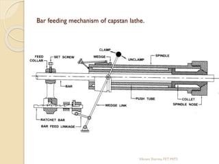
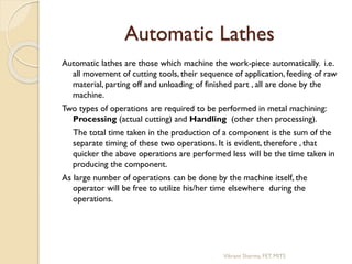
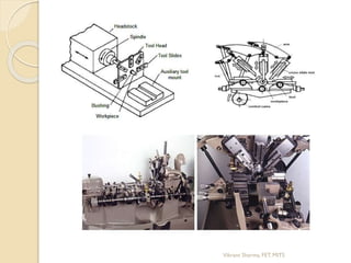
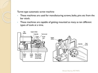
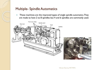
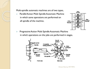
Capstan,Turret & Automatic Lathe
Vikrant Sharma
Assistant Professor
Mechanical Engineering Department
FET, MUST
Vikrantsharma.fet@modyuniversity.ac.in
9887342424
Limitations of a centre lathe
 The setting time for the job in terms of holding the job is
large.
 Only one tool can be used in the normal course. Sometimes,
the conventional tool post can be replaced by a square tool
post with four tools.
 The idle times involved in the setting and movement of tools
between the cuts is large.
Due to these difficulties, the centre lathe cannot be used for
production work. Thus, the centre lathe is modified to
improve the production rate.
Vikrant Sharma, FET. MITS
The various modified lathes are.
 turret and capstan lathes.
 automatics.
The improvements are achieved basically in the following areas.
 Work holding methods.
 Multiple tool availability.
 Automatic feeding of the tools.
 Automatic stopping of tools at precise locations.
 Automatic control of the proper sequence of operations.
Vikrant Sharma, FET. MITS
Capstan and Turret Lathes.
Turret and capstan lathes are the natural development of the engine
lathe, where the tailstock is replaced by an indexable multistation
tool head, called the capstan or the turret. This head carries a
selection of standard tool holders and special attachments. A
square turret is mounted on the cross slide in place of the usual
compound rest in engine lathe. Sometimes a fixed tool holder is
also mounted on the back end of the cross slide. Dimensional
control is effected by means of longitudinal (for lengths) and
traversal (for diameters) adjustable stops.
Vikrant Sharma, FET. MITS
In contrast to centre lathes, capstan and turret lathes
 are semiautomatic
 possess an axially movable indexable turret (mostly
hexagonal) in place of tailstock
 holds large number of cutting tools; upto four in indexable
tool post on the front slide, one in the rear slide and upto
six in the turret (if hexagonal) as indicated in the schematic
diagrams.
 are more productive for quick engagement and overlapped
functioning of the tools in addition to faster mounting and
feeding of the job and rapid speed change.
 enable repetitive production of same job requiring less
involvement, effort and attention of the operator for pre-
setting of work–speed and feed rate and length of travel of
the cutting tools
 are relatively costlier
 are suitable for batch production or small lot production.
Vikrant Sharma, FET. MITS
Bar feeding mechanism of capstan lathe.
Vikrant Sharma, FET. MITS
Turret indexing mechanism in capstan and turret lathe.
Vikrant Sharma, FET. MITS
Tooling Layout
Proper planning for systematic operations to be carried out on turret
and capstan lathes is done in advance before setting the work on
the lathe.
Tool layout schematically shows the type and configuration of the
cutting tools and their location and mounting.
 The cutting time for given operation is mainly controlled by proper
tooling , speed and feed.
 Much time is saved by taking combined cuts.
Vikrant Sharma, FET. MITS
Exercise
1.
2.
3.
Vikrant Sharma, FET. MITS
Automatic Lathes
Automatic lathes are those which machine the work-piece automatically. i.e.
all movement of cutting tools, their sequence of application, feeding of raw
material, parting off and unloading of finished part , all are done by the
machine.
Two types of operations are required to be performed in metal machining:
Processing (actual cutting) and Handling (other then processing).
The total time taken in the production of a component is the sum of the
separate timing of these two operations. It is evident, therefore , that
quicker the above operations are performed less will be the time taken in
producing the component.
As large number of operations can be done by the machine itself, the
operator will be free to utilize his/her time elsewhere during the
operations.
Vikrant Sharma, FET. MITS
Single Spindle Automatics
It operates on a single component at a time .
Commonly used single spindle automatic machines are:
 Swiss type automatic screw machine
 Turret type automatic screw machine
Swiss type automatic screw machine:
• This machine is use for parts of small diameter.
• Longitudinal feed are obtained by moving the head stock with the bar
instead of the tools.
Vikrant Sharma, FET. MITS
Turret type automatic screw machine
• These machines are used for manufacturing screws, bolts, pins etc from the
bar stock.
• These machines are capable of getting mounted as many as ten different
types of tools at a time.
Vikrant Sharma, FET. MITS
Multiple- Spindle Automatics
 These machines are the improved types of single spindle automatics.They
are made to have 2 to 8 spindles but 4 and 6 spindles are commonly used.
Vikrant Sharma, FET. MITS
Multi-spindle automatic machines are of two types,
 Parallel Action Multi Spindle Automatic Machine
in which same operations are performed on
all spindle of the machine.
 Progressive Action Multi Spindle Automatic Machine
in which operations on the jobs are performed in stages.
Vikrant Sharma, FET. MITS

Capstan, Turret & Automatic lathe

  • 1.
    Capstan,Turret & AutomaticLathe Vikrant Sharma Assistant Professor Mechanical Engineering Department FET, MUST Vikrantsharma.fet@modyuniversity.ac.in 9887342424
  • 2.
    Limitations of acentre lathe  The setting time for the job in terms of holding the job is large.  Only one tool can be used in the normal course. Sometimes, the conventional tool post can be replaced by a square tool post with four tools.  The idle times involved in the setting and movement of tools between the cuts is large. Due to these difficulties, the centre lathe cannot be used for production work. Thus, the centre lathe is modified to improve the production rate. Vikrant Sharma, FET. MITS
  • 3.
    The various modifiedlathes are.  turret and capstan lathes.  automatics. The improvements are achieved basically in the following areas.  Work holding methods.  Multiple tool availability.  Automatic feeding of the tools.  Automatic stopping of tools at precise locations.  Automatic control of the proper sequence of operations. Vikrant Sharma, FET. MITS
  • 4.
    Capstan and TurretLathes. Turret and capstan lathes are the natural development of the engine lathe, where the tailstock is replaced by an indexable multistation tool head, called the capstan or the turret. This head carries a selection of standard tool holders and special attachments. A square turret is mounted on the cross slide in place of the usual compound rest in engine lathe. Sometimes a fixed tool holder is also mounted on the back end of the cross slide. Dimensional control is effected by means of longitudinal (for lengths) and traversal (for diameters) adjustable stops. Vikrant Sharma, FET. MITS
  • 5.
  • 6.
    In contrast tocentre lathes, capstan and turret lathes  are semiautomatic  possess an axially movable indexable turret (mostly hexagonal) in place of tailstock  holds large number of cutting tools; upto four in indexable tool post on the front slide, one in the rear slide and upto six in the turret (if hexagonal) as indicated in the schematic diagrams.  are more productive for quick engagement and overlapped functioning of the tools in addition to faster mounting and feeding of the job and rapid speed change.  enable repetitive production of same job requiring less involvement, effort and attention of the operator for pre- setting of work–speed and feed rate and length of travel of the cutting tools  are relatively costlier  are suitable for batch production or small lot production. Vikrant Sharma, FET. MITS
  • 7.
  • 8.
  • 9.
    Bar feeding mechanismof capstan lathe. Vikrant Sharma, FET. MITS
  • 10.
    Turret indexing mechanismin capstan and turret lathe. Vikrant Sharma, FET. MITS
  • 11.
    Tooling Layout Proper planningfor systematic operations to be carried out on turret and capstan lathes is done in advance before setting the work on the lathe. Tool layout schematically shows the type and configuration of the cutting tools and their location and mounting.  The cutting time for given operation is mainly controlled by proper tooling , speed and feed.  Much time is saved by taking combined cuts. Vikrant Sharma, FET. MITS
  • 12.
  • 13.
  • 14.
  • 15.
    Automatic Lathes Automatic lathesare those which machine the work-piece automatically. i.e. all movement of cutting tools, their sequence of application, feeding of raw material, parting off and unloading of finished part , all are done by the machine. Two types of operations are required to be performed in metal machining: Processing (actual cutting) and Handling (other then processing). The total time taken in the production of a component is the sum of the separate timing of these two operations. It is evident, therefore , that quicker the above operations are performed less will be the time taken in producing the component. As large number of operations can be done by the machine itself, the operator will be free to utilize his/her time elsewhere during the operations. Vikrant Sharma, FET. MITS
  • 16.
    Single Spindle Automatics Itoperates on a single component at a time . Commonly used single spindle automatic machines are:  Swiss type automatic screw machine  Turret type automatic screw machine Swiss type automatic screw machine: • This machine is use for parts of small diameter. • Longitudinal feed are obtained by moving the head stock with the bar instead of the tools. Vikrant Sharma, FET. MITS
  • 17.
  • 18.
    Turret type automaticscrew machine • These machines are used for manufacturing screws, bolts, pins etc from the bar stock. • These machines are capable of getting mounted as many as ten different types of tools at a time. Vikrant Sharma, FET. MITS
  • 19.
    Multiple- Spindle Automatics These machines are the improved types of single spindle automatics.They are made to have 2 to 8 spindles but 4 and 6 spindles are commonly used. Vikrant Sharma, FET. MITS
  • 20.
    Multi-spindle automatic machinesare of two types,  Parallel Action Multi Spindle Automatic Machine in which same operations are performed on all spindle of the machine.  Progressive Action Multi Spindle Automatic Machine in which operations on the jobs are performed in stages. Vikrant Sharma, FET. MITS