Downloaded 352 times
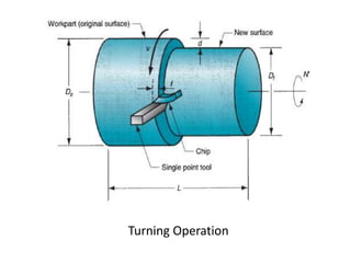
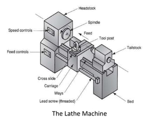
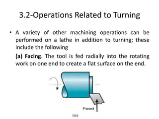
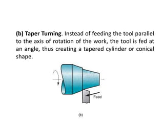
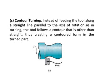
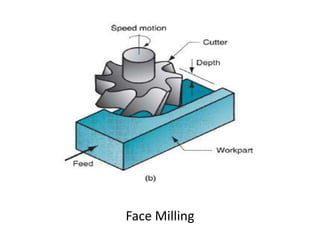
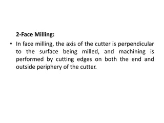

This document provides an overview of various machining processes including turning, drilling, and milling. It describes the key operations for each process and common machine tools used. Turning operations like facing and threading are performed on lathes. Drilling and related operations like reaming and tapping are usually done on drill presses. Milling can be classified as peripheral or face milling and is commonly done on knee-and-column or bed type milling machines. The document outlines the basic mechanics and applications of various machining techniques.