Downloaded 509 times


![NAME : SHETHWALA UZEFA M. (130640119113)
BRAHAMBHATT RUSHI (130640119103)
RABARI PRAKASH (130640119098)
BRANCH : MECHANICAL [B]
SUBJECT : MP-1](https://image.slidesharecdn.com/taperturningmethodforenginelathe-141125111659-conversion-gate01/85/Taper-turning-method-for-engine-lathe-2-320.jpg)


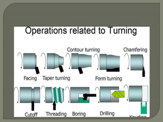
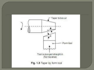

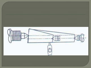

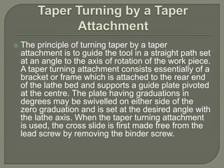
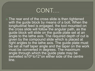


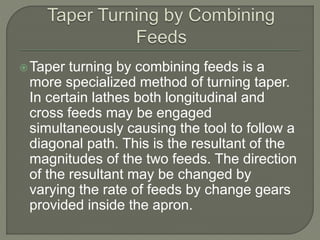


This document discusses different methods for taper turning on a lathe. The main methods described are using a broad nose form tool, setting over the tailstock center, swiveling the compound rest, using a taper turning attachment, and combining longitudinal and cross feeds. Each method has advantages and limitations for producing tapers of different lengths and angles. The taper turning attachment method allows for accurate taper turning of long workpieces and easy internal taper turning.


