Downloaded 2,480 times


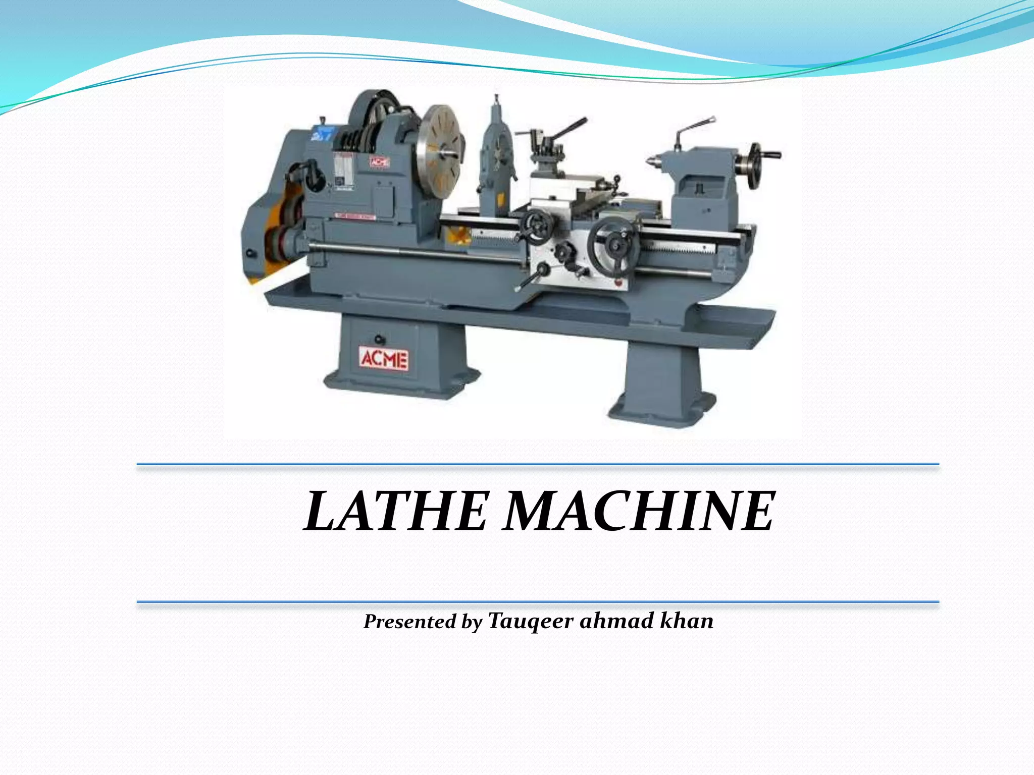

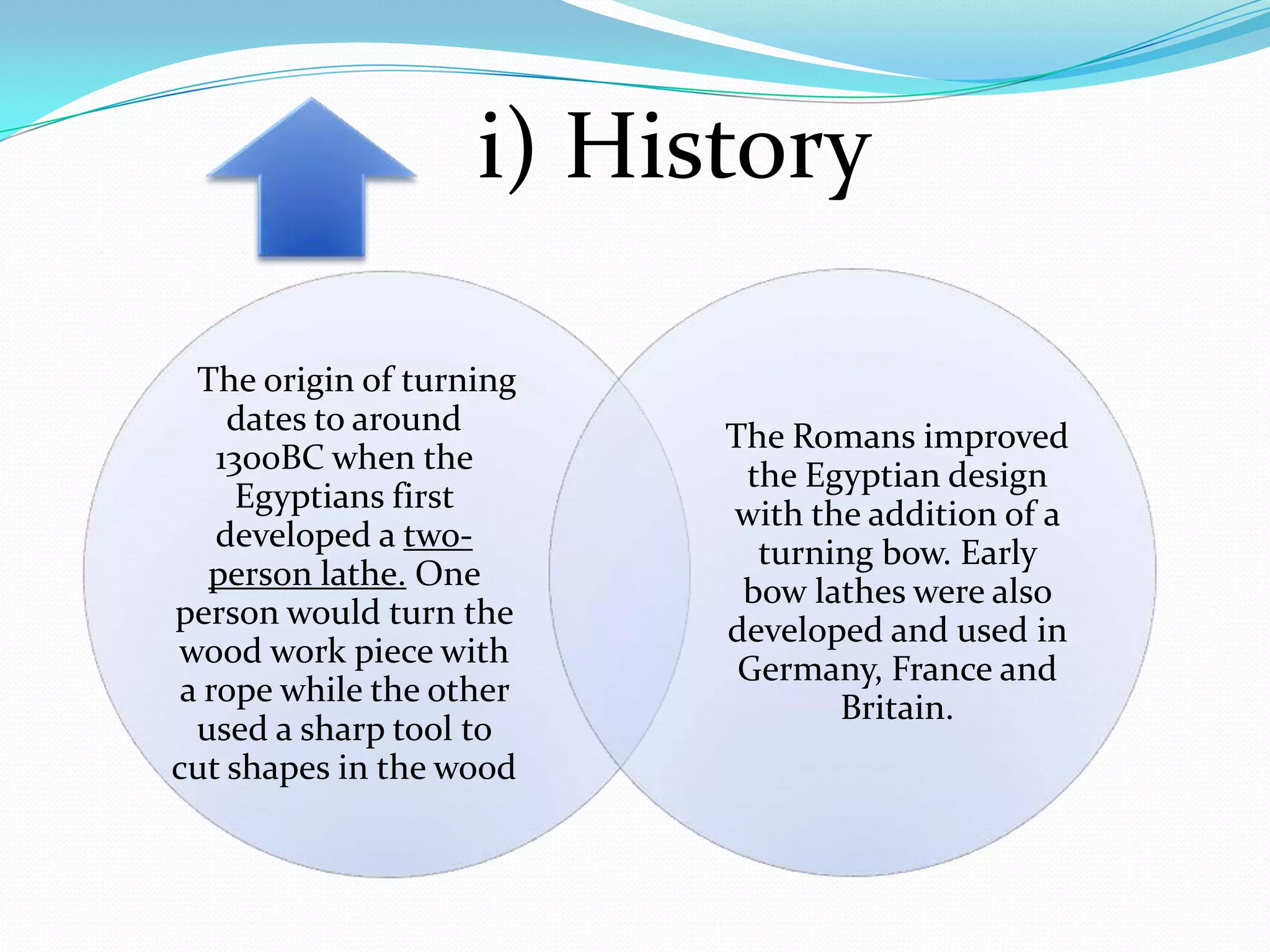

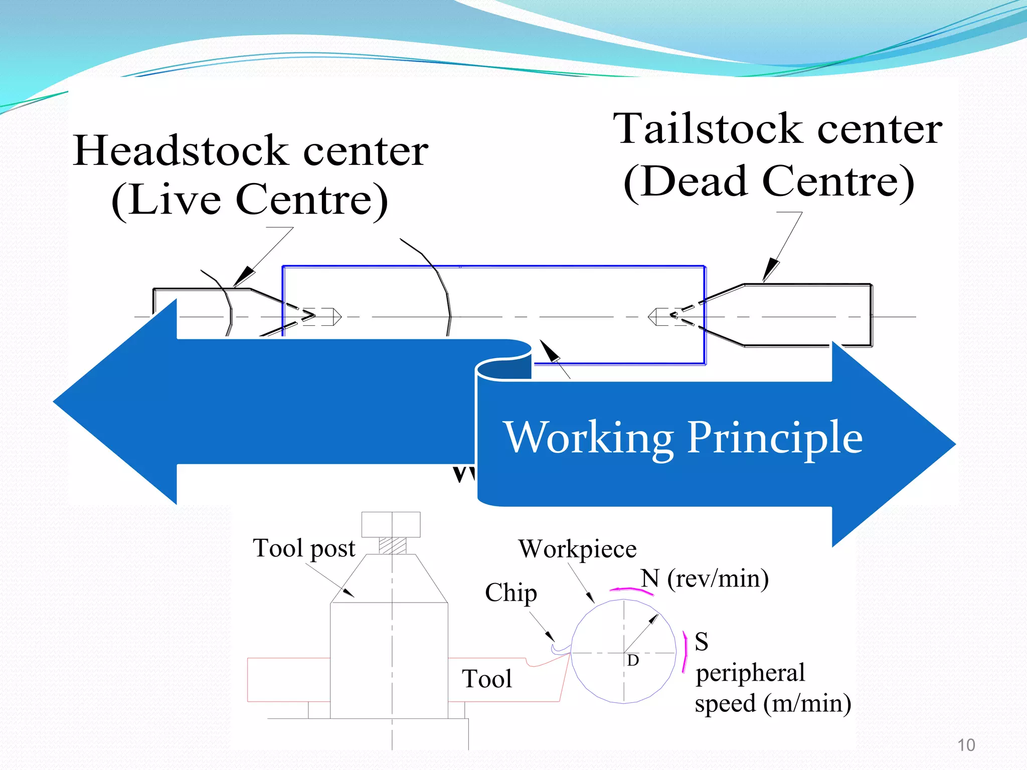
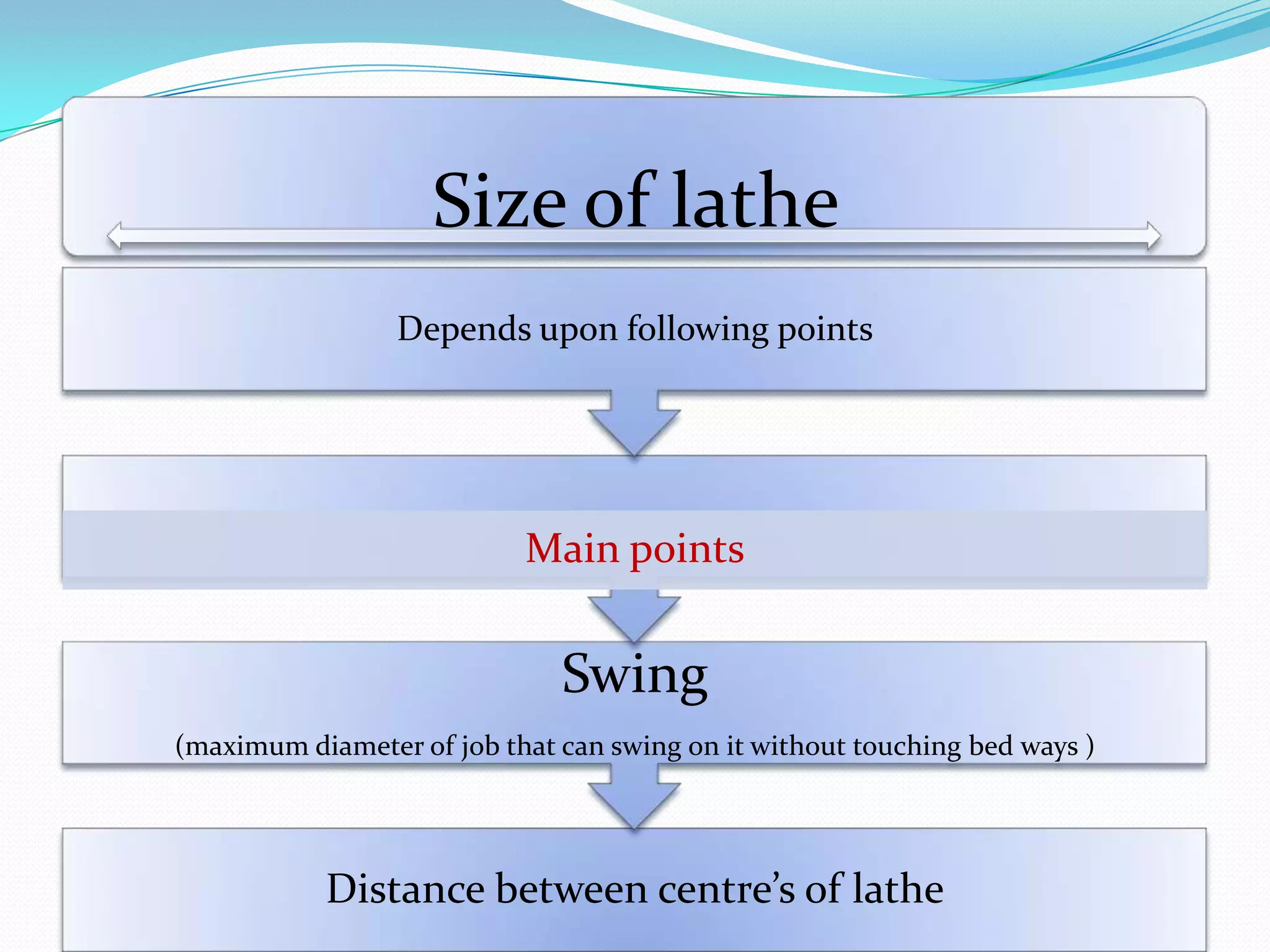


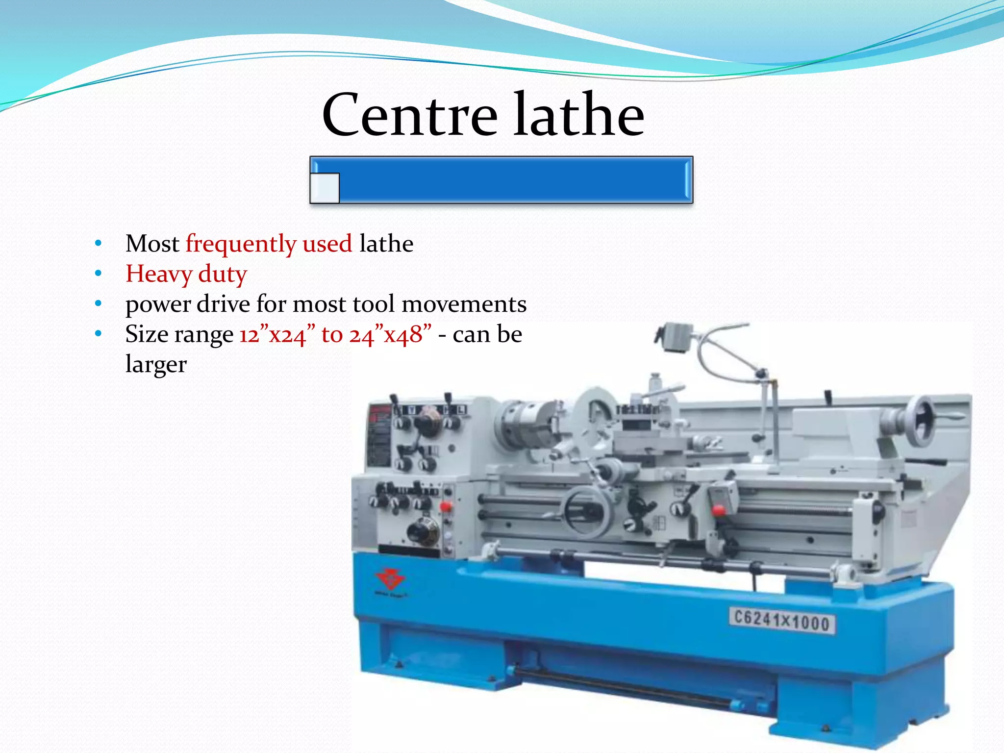
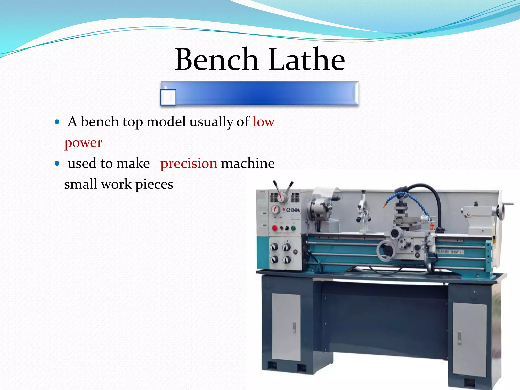
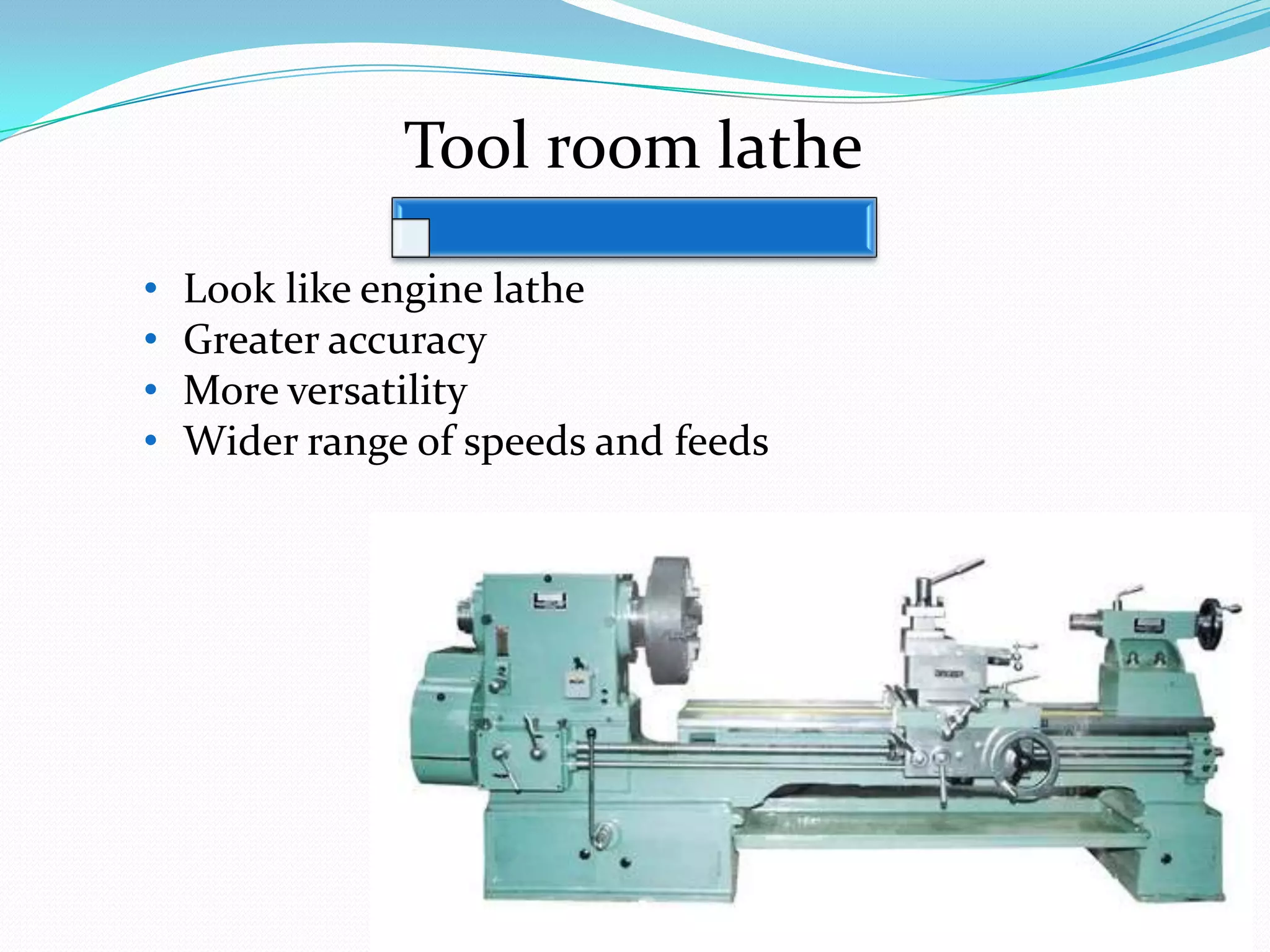
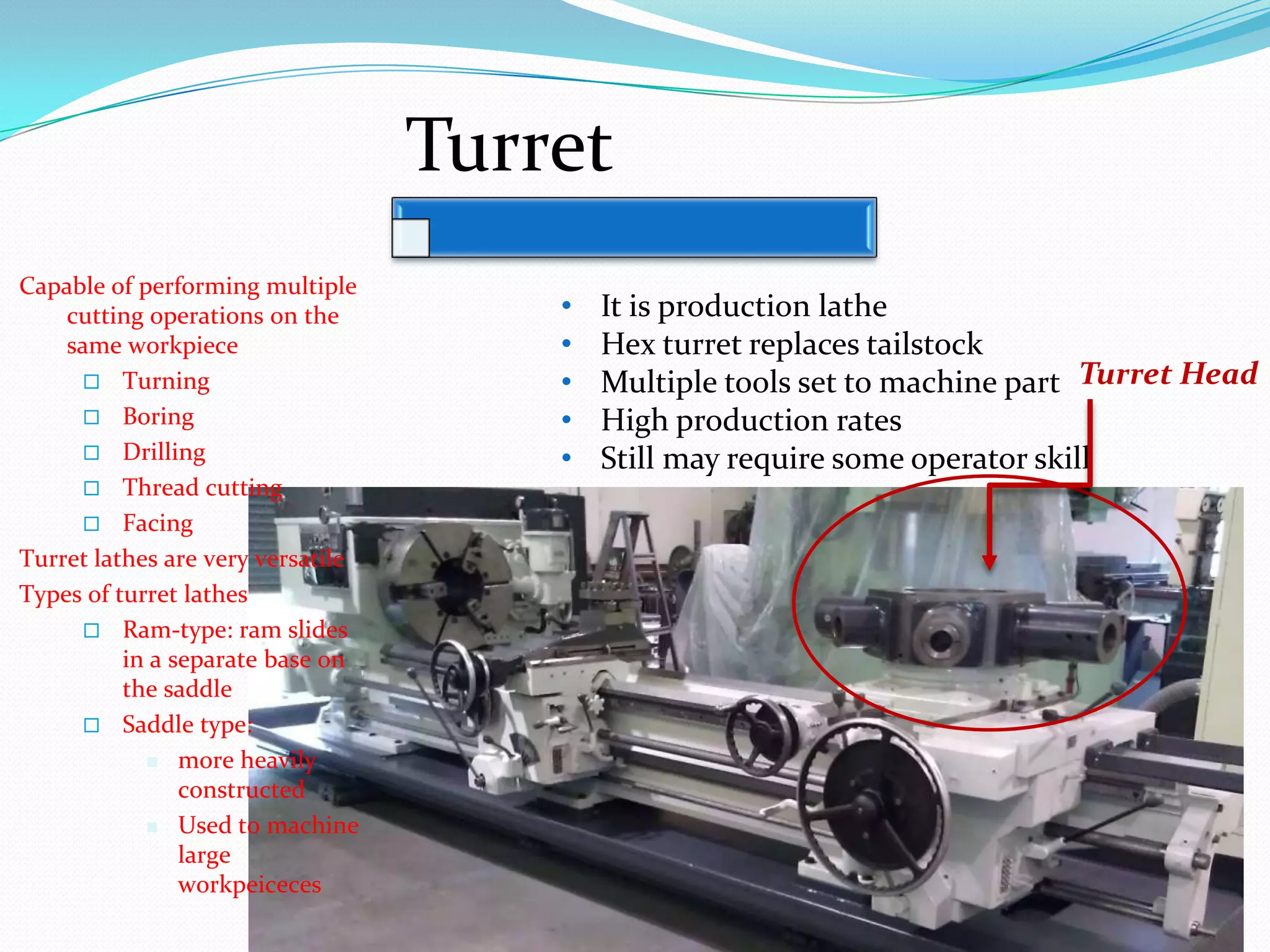

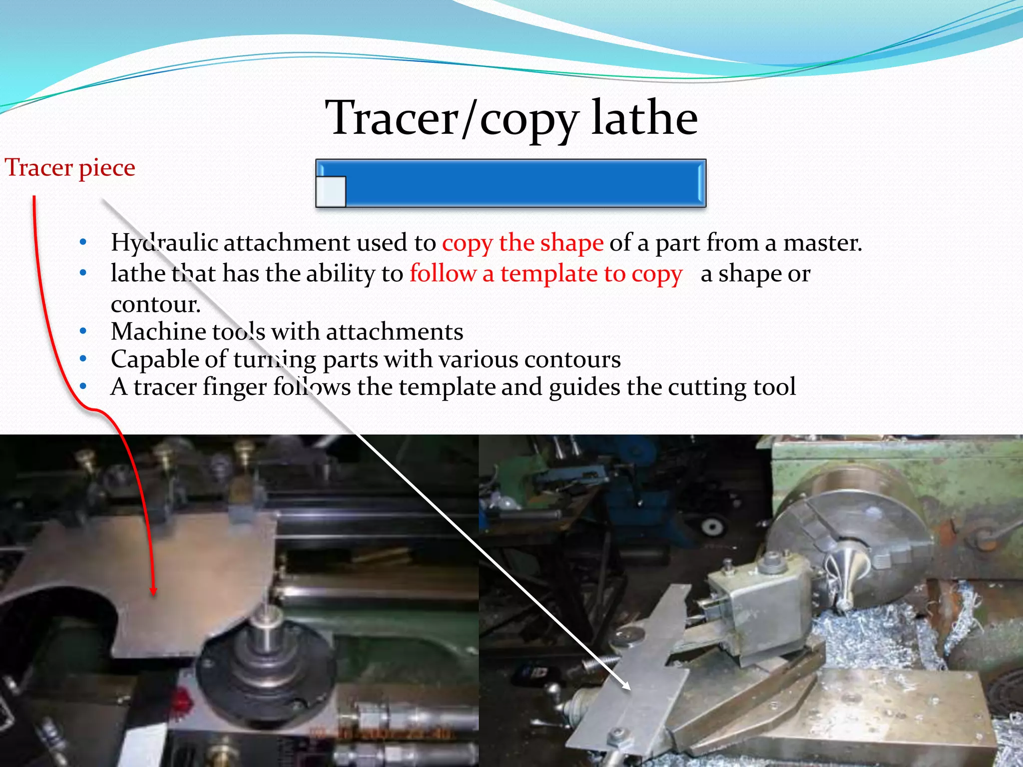
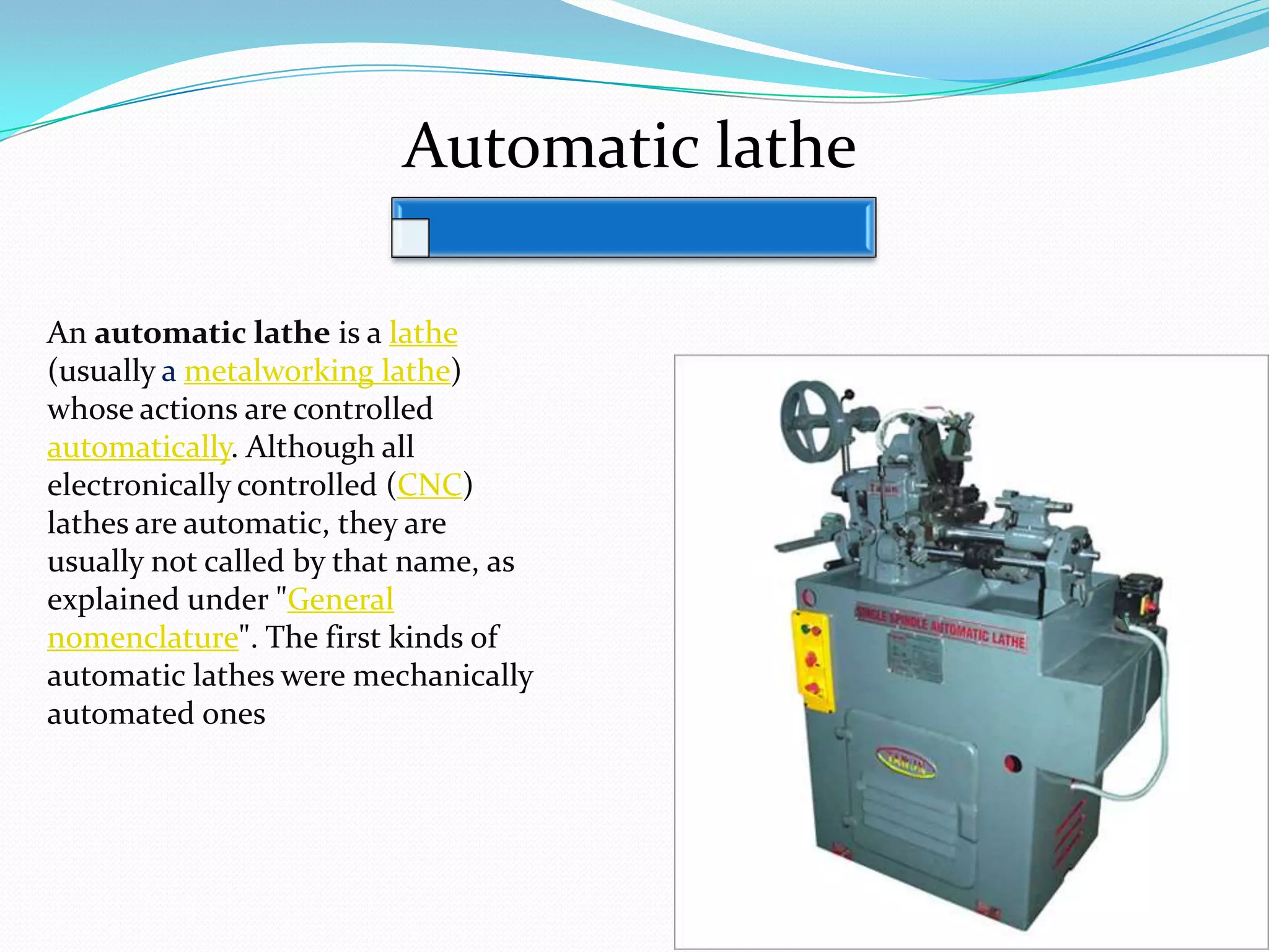
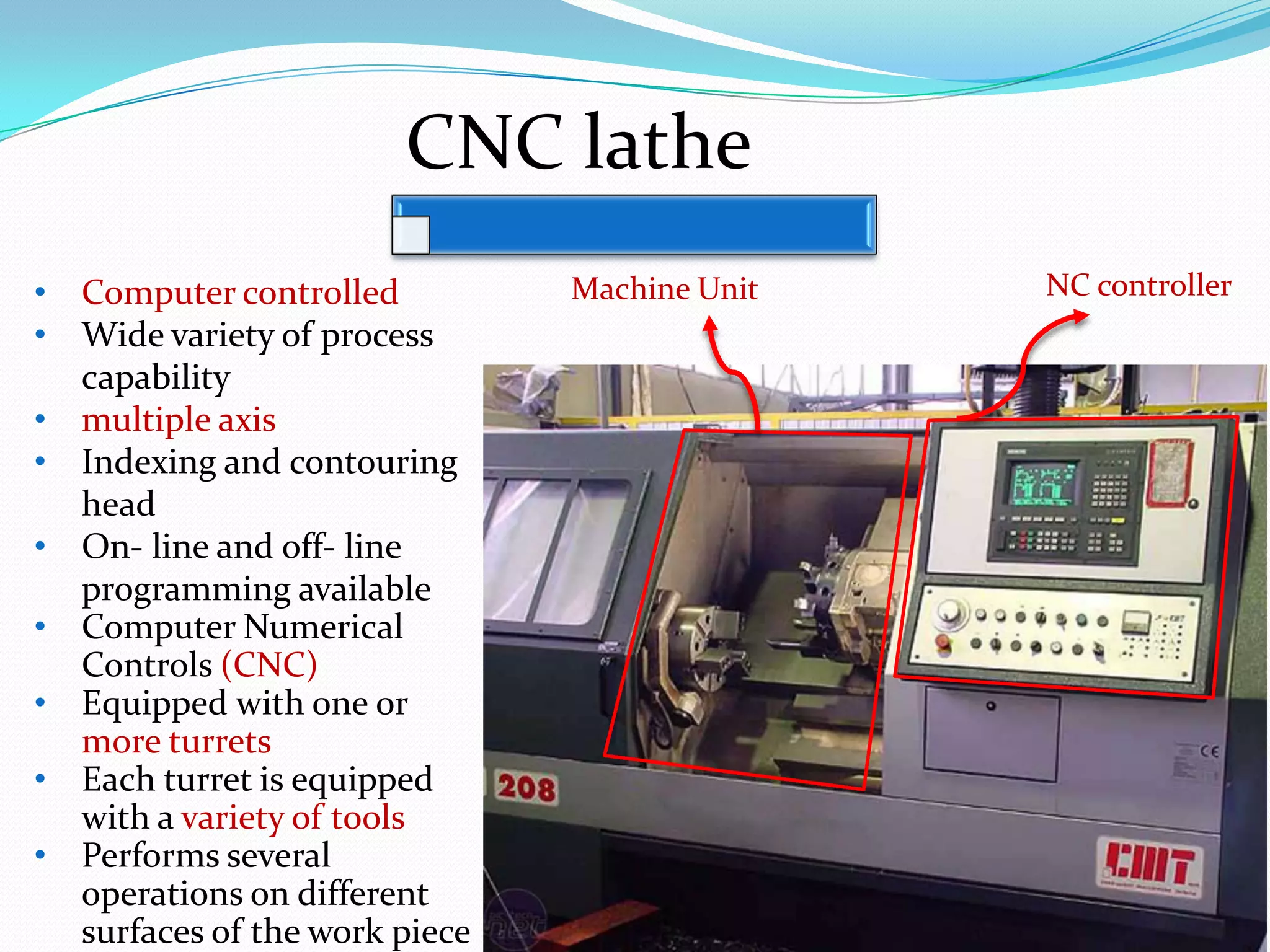

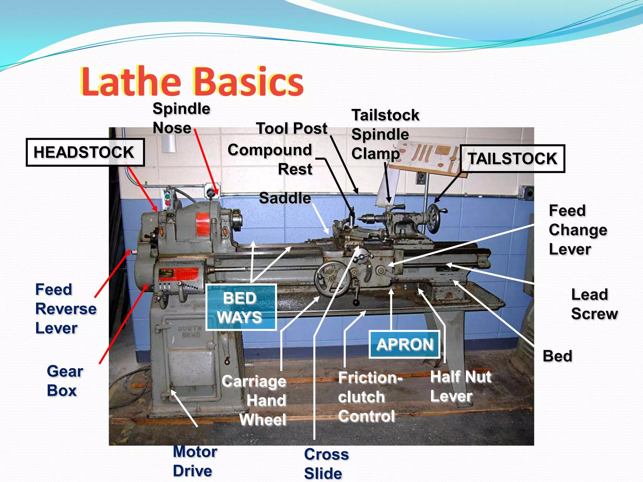


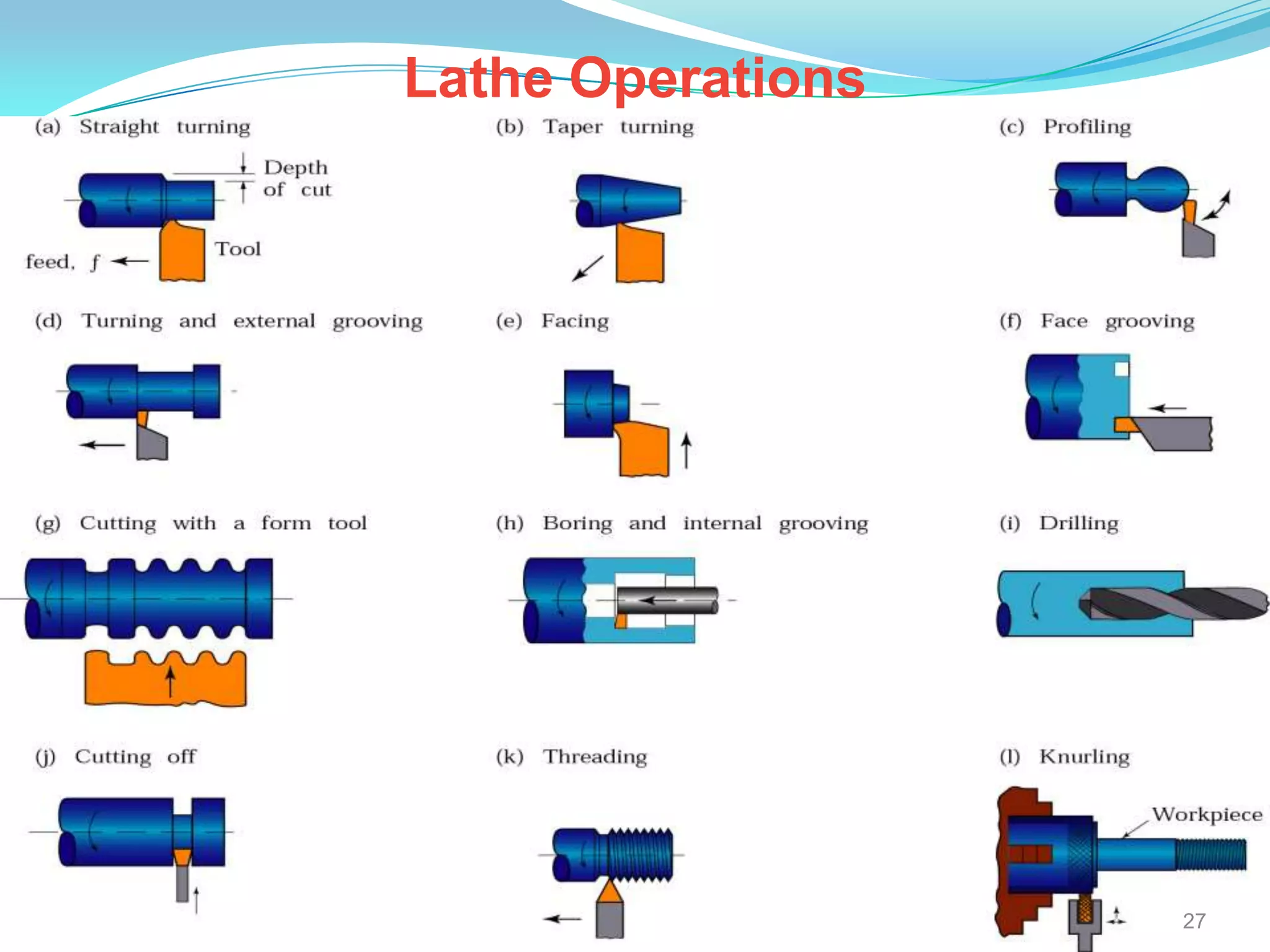
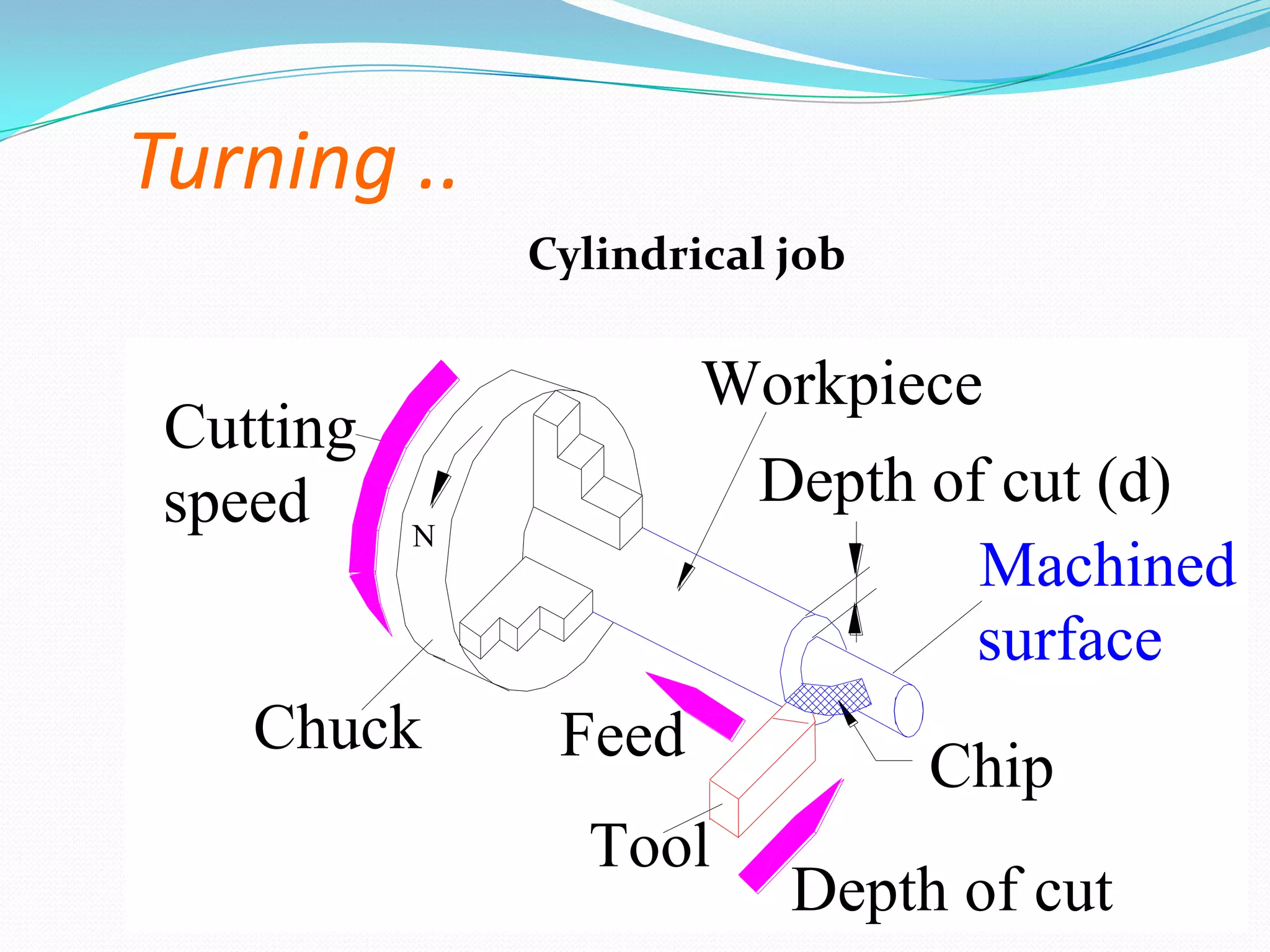
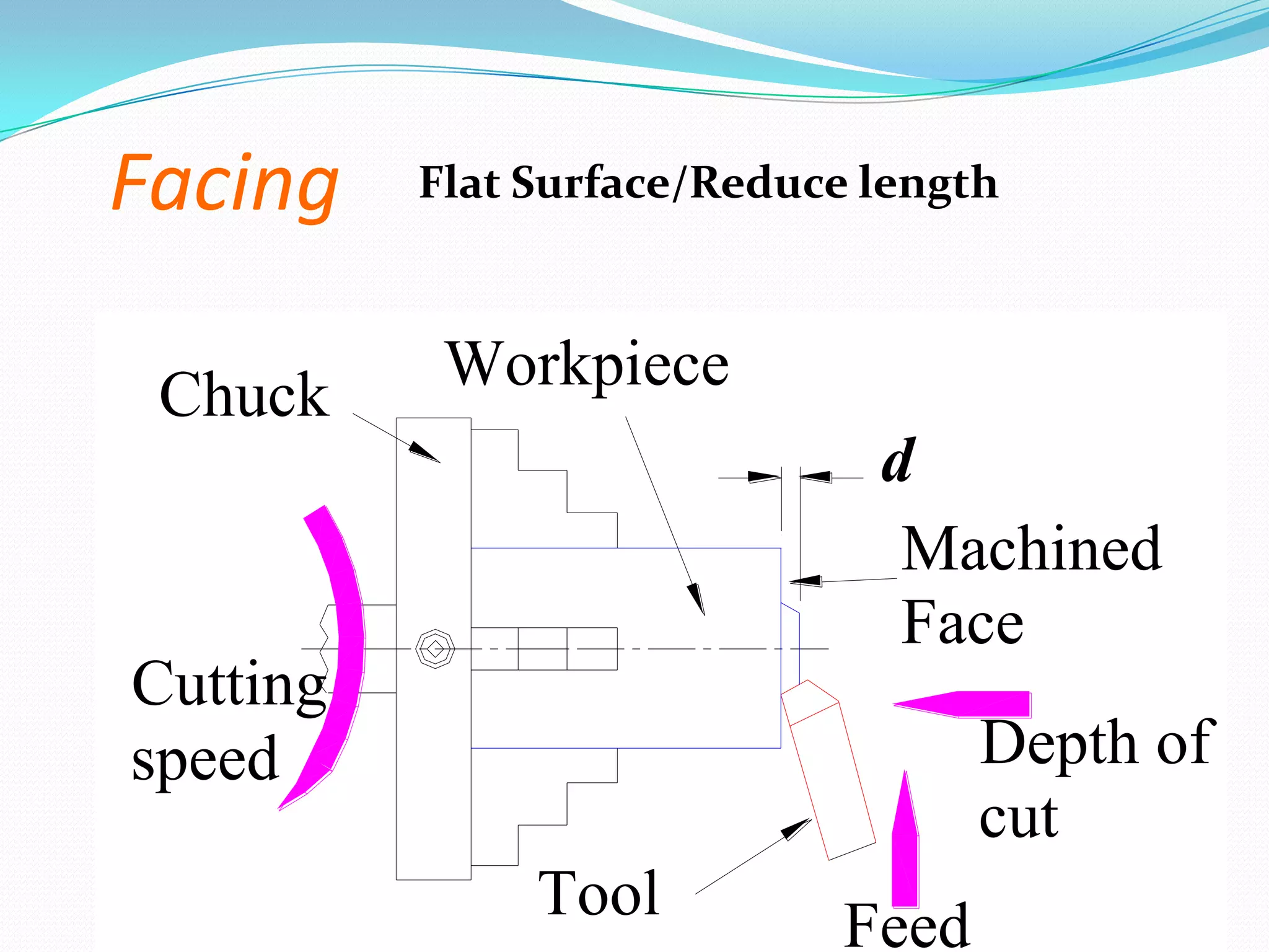
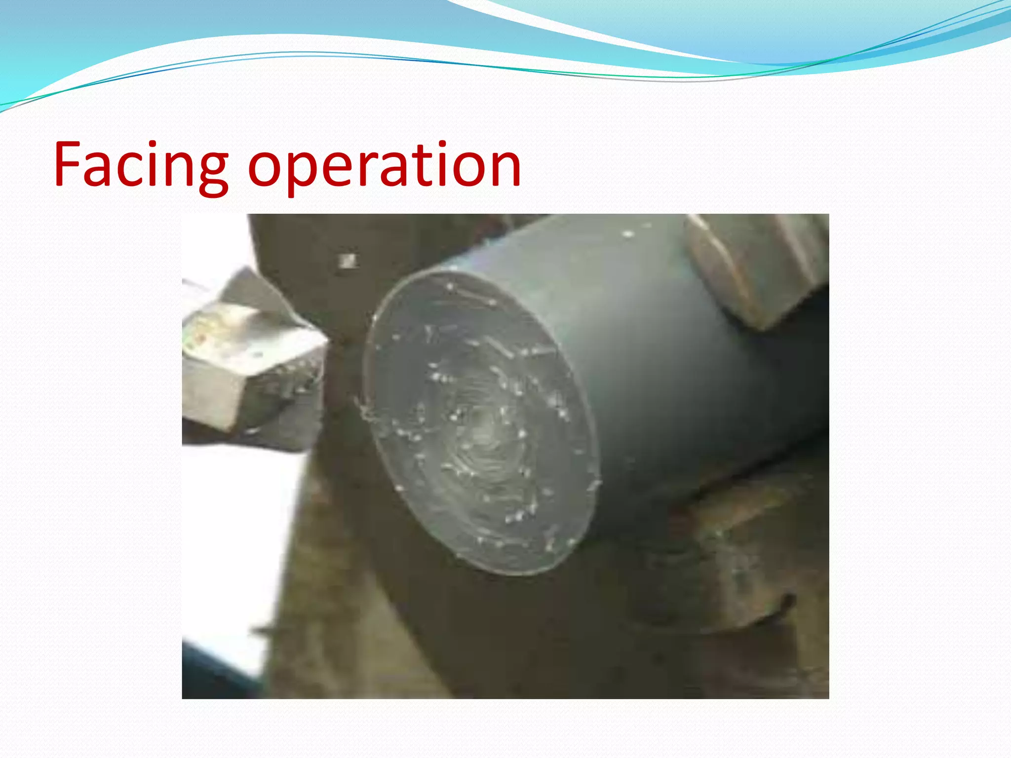


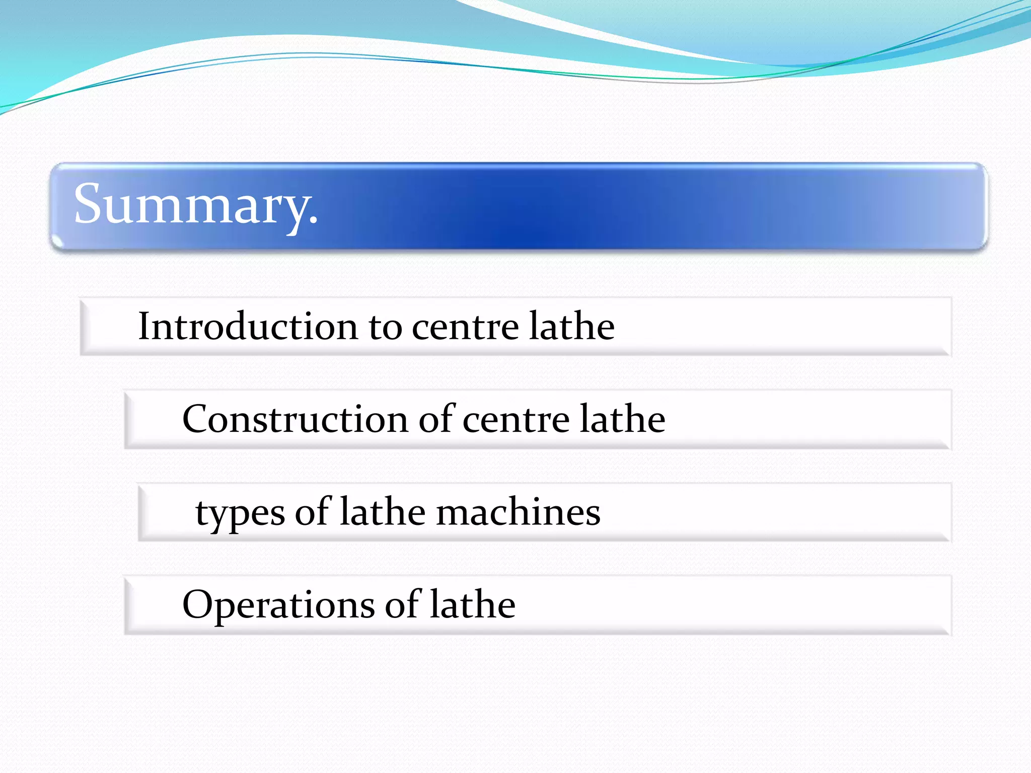


The document discusses lathe machines, including their history, construction, types, and operations. It defines a lathe as a machine tool used to cut or shape cylindrical workpieces. The key parts of a lathe are described, such as the headstock, tailstock, apron, and bed ways. Various types of lathes are examined, including center lathes, turret lathes, capstan lathes, tracer lathes, automatic lathes, and CNC lathes. Common lathe operations like turning, facing, boring, drilling, threading, and knurling are also explained.