
More Related Content
What's hot
What's hot (20)
Similar to Lathe
Similar to Lathe (20)
More from Pratik Kumar Shaw
More from Pratik Kumar Shaw (7)
Recently uploaded
Recently uploaded (20)
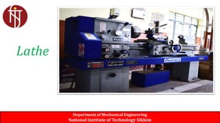
Lathe
- 1. Department of Mechanical Engineering National Institute of Technology Sikkim Lathe
- 2. Content Safetyprecautions on the lathe Typesof Lathe Specification and purposeof the centrelathe Identify main parts of the Centre lathe Statethe purposeof eachmainparts Method of Holdingwork Method of cuttingtapers Cuttingspeedon theLathe Department of Mechanical Engineering National Institute of Technology Sikkim
- 3. SafetyPrecautions Alwayswearapprovedsafetyglasses Rollupsleeves,removetie andtuck inloose clothing Neveroperate machineif safetyguards areremoved Stoplathe before measurework or clean,oil or adjustmachine Alwaysremovechuckkeyafteruse Alwaysremovechipswithbrush Department of Mechanical Engineering National Institute of Technology Sikkim
- 4. Types of Lathe Department of Mechanical Engineering National Institute of Technology Sikkim Bench Lathe Center Lathe Capstan Lathe
- 5. Types of Lathe Department of Mechanical Engineering National Institute of Technology Sikkim Turret Lathe CNC Lathe
- 6. CentreLathe Department of Mechanical Engineering National Institute of Technology Sikkim A lathe center, often shortened to center, is a tool that has been ground to a point to accurately position a workpiece on an axis. They usually have an included angle of 60°, but in heavy machining situations an angle of 75° is used.
- 7. LatheParts Department of Mechanical Engineering National Institute of Technology Sikkim
- 8. Department of Mechanical Engineering National Institute of Technology Sikkim HeadStock
- 9. Clamped on left-hand end of bed. Headstock spindle • Hollow cylindrical shaft supported by bearing • Provides drive through gears to work- holding devices • Live center, faceplate, or chuck fitted to spindle nose to hold and drive work Driven by stepped pulley or transmission gears. Department of Mechanical Engineering National Institute of Technology Sikkim HeadStock
- 10. Department of Mechanical Engineering National Institute of Technology Sikkim LatheBed Heavy, rugged casting Made to support working parts of lathe On top section are machined ways- Guide and align major parts oflathe
- 11. Department of Mechanical Engineering National Institute of Technology Sikkim • Used to move cutting tool along lathe bed • Consists of main parts – Saddle H-shaped casting mounted on top of lathe ways, provides means of mounting cross-slide and apron – Compound Rest – Cross-slide – Apron – Tool Post Carriage
- 12. Department of Mechanical Engineering National Institute of Technology Sikkim • Fastened to saddle • Houses gears and mechanism required to move carriage or cross-slide automatically • Locking-off lever inside apron prevents engaging split-nut lever and automatic feed lever at same time • Apron handwheel turned manually to move carriage along lathe bed Apron
- 13. Department of Mechanical Engineering National Institute of Technology Sikkim CrossSlide • Mounted on top of saddle • Provides manual or automatic cross movement for cutting tool • Compound rest (fitted on top of cross- slide) – Used to support cutting tool – Swiveled to any angle for taper- turning – Has graduated collar that ensure accurate cutting-tool settings (.001 in.) (also cross-slide)
- 14. It is fixed on top of the cross- slide, and can be turned (set) to any desired angle. The compound slide is useful for turning and boring short tapersand chamfers. Department of Mechanical Engineering National Institute of Technology Sikkim Compoundslide/Topslide
- 15. • Therearethreemaintypesoftool postused for holdinglathe cuttingtools: Department of Mechanical Engineering National Institute of Technology Sikkim ToolPost Ring and rocker Four-way turret Quick -change
- 16. Department of Mechanical Engineering National Institute of Technology Sikkim TailStock Adjusted for taper or parallel turning by two screws set in base Tailstock clamp locks tailstock in any position along bed of lathe Tailstock spindle has internal taper to receive dead center provides support for right-hand endof work
- 17. Producecylindricalwork Typeof lathe Programmeto carry outtask Useto tighten thechuck Typesof lathe useinschool workshops Useto makeprecisionwork and smallworkpieces. lathe which havemultiple tools Toolpost that doesn’tneed packing Useto produce shorttapers Made to support working parts of lathe Foundat the left sideofthe bed Foundat the right sideof the bed Holdfour tools at the same time Used to move cutting tool along lathe bed Parts of the machine use when facing off Department of Mechanical Engineering National Institute of Technology Sikkim Quizpoints
- 18. Copyright © The McGraw-Hill Companies, Inc. Permission required for reproduction or display. Department of Mechanical Engineering National Institute of Technology Sikkim Swing- the largest work diameter that can be swung for the lathe bed. The distance between the headstock and tailstock center. Length of the bed in a meter. The pitch of the lead screw. Horsepower of the machine. Speed range and the number of speeds of HS spindle. LatheSpecification
- 19. • The cutting speed (v) of a tool is the speed at which the metal is removed by the tool from the workpiece. In a lathe, it is the peripherical speed of the work past the cutting tool expressed in meters per minute. • The feeds(f) of the cutting tool in lathe work are the distance the tool advances for each revolution of the work. A feed is expressed in millimeters per revolution. • The depth of cut (d) is the perpendicular distance measured from the machined surface to the uncut surface of the workpiece. The depth of cut changes inversely as the cutting speed. For general purpose, the ratio of the depth of cut to the feed varies from 10:1. • The machining time (t) is the time by which machining process is completed. Time for the lathe work can be calculated for a particular operation if the speed of the job, feed and length of the job is known. Department of Mechanical Engineering National Institute of Technology Sikkim MachiningParameters
- 20. 47-42 • Rate at which point on work circumference travels past cutting tool • expressed in meters per minute (m/min) • Important to use correct speed for material –Too high: cutting-tool breaks down rapidly –Too low: time lost, low production rates Department of Mechanical Engineering National Institute of Technology Sikkim CuttingSpeed
- 21. • The softer the work material, the faster the recommended cutting speed Department of Mechanical Engineering National Institute of Technology Sikkim Cuttingspeedselection • The harder the cutting tool material, the faster the cutting speed. The softer the cutting tool material, the slower the recommended cutting speed
- 22. • The material being cut • The rigidity and condition of the machine • The material of which the tool is made from • The depth of cut and the feed rate • Availability of coolant (cutting fluid) Department of Mechanical Engineering National Institute of Technology Sikkim FactorsthatDeterminecuttingspeed
- 23. Material beingcut Cuttingspeed (metres/minute) Mildsteel Cast iron Highcarbonsteel Brass Bronze Aluminium 20to28 18to25 12to18 45to90 15to21 Upto300 47-49 Department of Mechanical Engineering National Institute of Technology Sikkim LatheCuttingSpeedsfordifferentMaterials
- 24. 47-50 • Given in metres per minute • spindle speed of machine (N) and diameter of work must be known S (m/min)= πDN/1000 • Where π= 22/7 or 3.142 D= diameter of material in mm. N= Spindle speed(rev/min) Department of Mechanical Engineering National Institute of Technology Sikkim CalculatingLathecuttingspeed
- 25. • Calculate rev/min required to rough-turn 150mm diameter piece of machinesteel(CS90)cuttingspeedis30m/min. • Find the cutting speed of a 50mm diameter bar being turned with a spindleof 178 rev/min. Examples Department of Mechanical Engineering National Institute of Technology Sikkim Exercise • Calculate the spindle speed required to turn 200mm diameter piece of high speed steel, if the cutting speed is 28 m/min. • Find the cutting speed of a 15mm diameter bar being turned with a spindle of 955 rev/min. • Determine the lathe speed to cut a 40mm diameter at 30 m/min
- 26. 1. What is cutting speed for turning? 2. State the unit for cutting speed. 3. Which of the following materials have the highest cutting speed. 1.Brass 2. Bronze 3. mild steel. Give reasons for your choice. 4. List four factors that determine the cutting speed. Explain any two factors. Department of Mechanical Engineering National Institute of Technology Sikkim Classwork
- 27. • Divided into twocategories – Work-holding,-supporting, and–driving devices • Lathecenters,chucks,faceplates • Mandrels, steadyandfollowerrests • Lathedogs,driveplates – Cutting-tool-holding devices • Straight andoffsettoolholders • Threadingtoolholders, boringbars • Turret-typetoolposts Department of Mechanical Engineering National Institute of Technology Sikkim LatheAccessories
- 28. • Work to be turned between centers must have center hole drilled in each end • Support during cutting • Most common have solid Morse taper shank 60º centers, steel with carbide tips • Care to adjust and lubricate occasionally Department of Mechanical Engineering National Institute of Technology Sikkim LatheCenters
- 29. Lathe centres is used as a support at the end of a work. It is usually madefrom carbon tool steel. Thereare three (3) main types of Lathe centres: Livecentre (Revolvingcentre) Deadcentre Halfcentre Department of Mechanical Engineering National Institute of Technology Sikkim TypeofLatheCentres
- 30. It isconstructedsothat the60°centerrunsinits own bearings. Thelive centre fits in the spindle(headstock)and rotates with thespindle. Usedwhen turning betweencentres Department of Mechanical Engineering National Institute of Technology Sikkim Livecentre(RevolvingCentre) Centre in Headstock Spindle
- 31. Fits in the tailstock spindle, remains stationary while the workrotatesonitspoint Department of Mechanical Engineering National Institute of Technology Sikkim Deadcentre Halfcenter A centre that is cut away almost to its point. It isoften usedin the tailstockfor facing up to or for turning close to the endof thework.
- 32. Department of Mechanical Engineering National Institute of Technology Sikkim • Usedextensivelyfor holding workfor machiningoperations – Work largeor unusualshape • Most commonly usedlathechucks – Three-jawuniversal – Four-jawindependent – Colletchuck Chuck
- 33. • Holdsround andhexagonalwork • Graspswork quickly andaccurate • Threejawsmove simultaneously when adjustedbychuckKey Department of Mechanical Engineering National Institute of Technology Sikkim Three-jawUniversalChuck
- 34. Usedto hold round, square, hexagonal,and irregularly shaped workpieces Hasfour jaws – Eachcanbeadjustedindependently by chuckKey Jawscanbereversedto hold work by inside diameter Department of Mechanical Engineering National Institute of Technology Sikkim Four-JawIndependentChuck
- 35. Collet chuck is used to hold small workpieces. Usedfor high-precisionwork Spring collets available to hold round, square, or hexagon- shapedworkpieces Each collet has range of only few thousandths of an inch over or undersizestampedon collet Department of Mechanical Engineering National Institute of Technology Sikkim ColletChuck
- 36. | Special adapter fitted into taper of headstock spindle, and hollow draw bar having internal thread inserted in opposite end of headstock spindle. It draws collet into tapered adapter causing collet to tighten on workpiece. Department of Mechanical Engineering National Institute of Technology Sikkim ColletChuck
- 37. A lathe dog ( lathe carrier) is a device that clamps around the workpiece and allows the rotary motion of the machine's spindle to be transmitted to the workpiece. A carrier is most often used when turning between centers on a lathe. Department of Mechanical Engineering National Institute of Technology Sikkim LatheDogs/Carrier
- 38. Standard bent-tail lathe dog Most commonly used for round workpieces Available with square-head setscrews of headless setscrews Straight-tail lathe dog Driven by stud in driveplate Used in precision turning Department of Mechanical Engineering National Institute of Technology Sikkim TypesofLatheDogs
- 39. Safetyclamplathedog Usedto hold variety ofwork Widerangeofadjustment Clamplathe dog Widerrange thanothers Usedon allshapes Department of Mechanical Engineering National Institute of Technology Sikkim TypesofLatheDogs
- 40. Department of Mechanical Engineering National Institute of Technology Sikkim WorkHeldBetweenCentres
- 41. A faceplate is the basic workholding accessory for a lathe. It is a circular metal plate which fixes to the end of the lathe spindle. The workpiece is then clamped to the faceplate, typically using t-nuts in slots in the faceplate, or less commonly threaded holes in the faceplate itself. Department of Mechanical Engineering National Institute of Technology Sikkim Faceplate Used to hold work too large or shaped so it cannot be held in chuck or between centers Usually equipped with several slots to permit use of bolts to secure work
- 42. Used to support long work held in chuck or between lathe centers – Prevent springing Located on and aligned by ways of the lathe Positioned at any point along lathe bed Three jaws tipped with plastic, bronze or rollers may be adjusted to support any work diameter with steadyrest capacity Department of Mechanical Engineering National Institute of Technology Sikkim SteadyRest/FixedSteady
- 43. Department of Mechanical Engineering National Institute of Technology Sikkim SteadyRest
- 44. Mounted on saddle Travels with carriage to prevent work from springing up and away from cutting tool Cutting tool generally positioned just ahead of follower rest Provide smooth bearing surface for two jaws of follower rest Department of Mechanical Engineering National Institute of Technology Sikkim TravellingSteady/FollowerRest
- 45. Department of Mechanical Engineering National Institute of Technology Sikkim TravellingSteady
- 46. • Holds internally machined workpiece between centers so further machining operations are concentric with bore • Several types, but most common – Plain mandrel – Expanding mandrel – Stepped mandrel – Double cone mandrel Department of Mechanical Engineering National Institute of Technology Sikkim Mandrel
- 47. Plain Mandrel Department of Mechanical Engineering National Institute of Technology Sikkim TypesofMandrel Expanding Mandrel
- 48. Department of Mechanical Engineering National Institute of Technology Sikkim ColletChuck TypesofMandrel Stepped Mandrel Double cone Mandrel
- 49. Department of Mechanical Engineering National Institute of Technology Sikkim TaperTurning Taper Turning: A conical surface produced on a lathe is called taper turning. The tool moves at an angle to the axis of rotation. Methods of Taper turning: Form tool method Compound rest method Taper attachment method Tailstock set over method
- 50. Department of Mechanical Engineering National Institute of Technology Sikkim MethodsofTaperturning: Form tool method It is one of the simplest methods used to produce short taper. A broad nose tool having straight cutting edge is set on to the work at half taper angle and is fed straight into the work. It requires excessive cutting pressure which may distort the workpiece due to vibration. Compound rest method This method is used to produce short and steep taper. The compound rest is swiveled to the required angle and clamped in position, it can be moved up to 45° on both sides.
- 51. Taper: 2L tan D1 D2 Department of Mechanical Engineering National Institute of Technology Sikkim UsingthecompoundSlide
- 52. 105 d = small diameter k = unit length of taper l = total length of taper D = large diameter If know d, k, and l, D may be calculated. D equal to small dia + amount of taper. Amount of taper is equal to 1/k, so total taper equals l/k. D = d + total taper D = d + l/k Department of Mechanical Engineering National Institute of Technology Sikkim Metric Taper Calculations
- 53. Calculate tailstock offset required to turn a 1:30 taper X 60 mm long on a workpiece 300 mm long. The small diameter of tapered section is 20 mm. Determine the angle at which the compound rest would be swiveled for cutting a taper on a workpiece having a length of 150 mm and outside diameter 80 mm. The smallest diameter on the tapered end of the rod should be 50 mm and the required length of the tapered portion is 80 mm. Department of Mechanical Engineering National Institute of Technology Sikkim TaperTurningCalculation
- 54. D 4 0 d 2 0 O L 1 0 5 l 5 0 D 5 0 d 2 0 O L 1 0 0 l 4 0 D 6 0 d 3 0 O L 1 2 0 l 6 0 Department of Mechanical Engineering National Institute of Technology Sikkim Usingthecompoundslide