Lathe Machine
Classification oflathe machines: Lathe machines are
classified depending on number of factors.
A. Classification according to configuration:
1. Horizontal lathe
In this lathe, Lathe axis is horizontal.
Its Center height matches with the height of the
common man.
It Occupies relatively more space but it is more
common in use.
2.
Vertical lathe machines
•These lathes are vertical
• Their lathe Axis is vertical
• These are large machines
• They Occupy less space as axis is vertical
• These are Less common in use.
3.
According to thepurpose of use
• 1. General purpose lathe machines
These are Versatile .
These are Widely used
These machines are Suitable for any type of job, any type of
material, any design.
Ex. Center lathe
2. Single purpose lathe machines
These are Used for performing only one or max. two operations
Ex. Only facing or max. facing and turning lathe
only grooving or only roll turning lathe.
4.
3. Special purposelathe machines
These lathes are Used only for a special purpose.
These are used to Performs only certain type of
operations for certain number of times.
It Performs only certain operations for a long
time.
Ex gear blank machining lathe.
5.
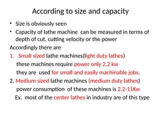
According to sizeand capacity
• Size is obviously seen
• Capacity of lathe machine can be measured in terms of
depth of cut, cutting velocity or the power
Accordingly there are
1. Small sized lathe machines(light duty lathes)
these machines require power only 2.2 kw
they are used for small and easily machinable jobs.
2. Medium sized lathe machines (medium duty lathes)
power consumption of these machines is 2.2-11Kw
Ex. most of the center lathes in industry are of this type
6.
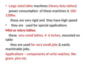
• Large sizedlathe machines (Heavy duty lathes)
power consumption of these machines is 100-
120Kw.
these are very rigid and they have high speed
• they are used for special applications
Mini or micro lathes
these very small lathes, 4- 6 inches, mounted on
table
they are used for very small jobs & easily
machinable jobs.
Applications – components of wrist watches, like
gears, pins etc.
7.
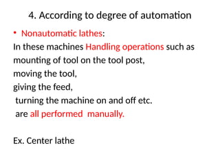
4. According todegree of automation
• Nonautomatic lathes:
In these machines Handling operations such as
mounting of tool on the tool post,
moving the tool,
giving the feed,
turning the machine on and off etc.
are all performed manually.
Ex. Center lathe
8.
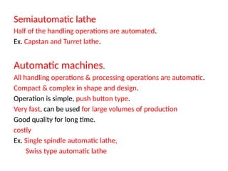
Semiautomatic lathe
Half ofthe handling operations are automated.
Ex. Capstan and Turret lathe.
Automatic machines.
All handling operations & processing operations are automatic.
Compact & complex in shape and design.
Operation is simple, push button type.
Very fast, can be used for large volumes of production
Good quality for long time.
costly
Ex. Single spindle automatic lathe,
Swiss type automatic lathe
9.
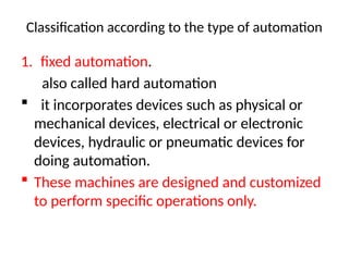
Classification according tothe type of automation
1. fixed automation.
also called hard automation
it incorporates devices such as physical or
mechanical devices, electrical or electronic
devices, hydraulic or pneumatic devices for
doing automation.
These machines are designed and customized
to perform specific operations only.
10.
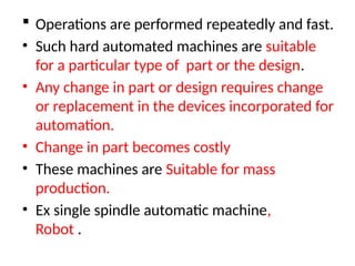
Operations areperformed repeatedly and fast.
• Such hard automated machines are suitable
for a particular type of part or the design.
• Any change in part or design requires change
or replacement in the devices incorporated for
automation.
• Change in part becomes costly
• These machines are Suitable for mass
production.
• Ex single spindle automatic machine,
Robot .
11.
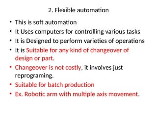
2. Flexible automation
•This is soft automation
• It Uses computers for controlling various tasks
• It is Designed to perform varieties of operations
• It is Suitable for any kind of changeover of
design or part.
• Changeover is not costly, it involves just
reprograming.
• Suitable for batch production
• Ex. Robotic arm with multiple axis movement.
12.
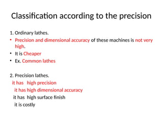
Classification according tothe precision
1. Ordinary lathes.
• Precision and dimensional accuracy of these machines is not very
high.
• It is Cheaper
• Ex. Common lathes
2. Precision lathes.
it has high precision
it has high dimensional accuracy
it has high surface finish
it is costly
13.
According to thenumber of spindles
1. Single spindle machines
they have one spindle
it performs only one job at a time
ex. Lathe machines
2. Multispindle machines
14.
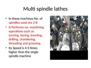
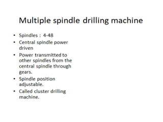
Multi spindle lathes
•In these machines No. of
spindles used are 2-8
• It Performs no. machining
operations such as
turning, boring, knurling,
drilling, chamfering,
threading and grooving.
• Its Speed is 4-5 times
higher than the single
spindle machine
15.
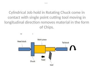
Turning Principle
Cylindrical Jobhold in Rotating Chuck come in
contact with single point cutting tool moving in
longitudinal direction removes material in the form
of Chips.
16.
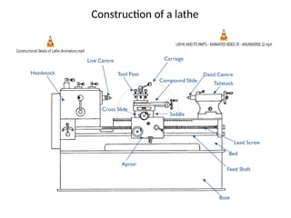
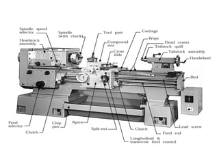
Construction of alathe
Constructional Details of Lathe (Animation).mp4
LATHE AND ITS PARTS - ANIMATED VIDEO 29 - ANUNIVERSE 22.mp4
17.
Constructional Details ofLathe (Animation).mp4
Constructional Features Of Lathe Machine _ Lathe Machine ke Parts _ In Hindi _ Akash K Tutorials.mp4
18.
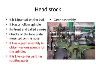
Head stock
• Itis Mounted on the bed
• It Has a hollow spindle
• Its Front end called a nose
• Chucks or the face plate
mounted on the nose
• It Has a gear assembly to
obtain various speeds for
the spindle.
• It is Live center as it has
rotating parts
• Gear assembly
19.
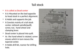
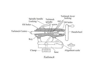
Tail stock
• Itis called as Dead center
• It is Mounted on the bed opposite
to head stock in a perfect alignment.
• It Holds and supports the job
• It Consists mainly of a tail stock
center, tailstock spindle(quill),
screw, nut, hand wheel and
clamping lever.
• Dead center is placed into quill.
• As the hand wheel is rotated, screw
moves which in turn moves the
tapered center.
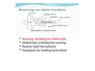
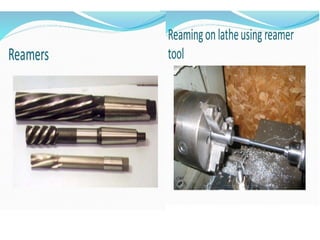
• It Holds drill bit, reamer for drilling
hole.
21.
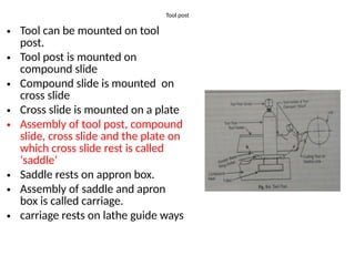
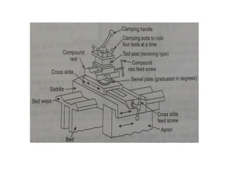
Tool post
• Toolcan be mounted on tool
post.
• Tool post is mounted on
compound slide
• Compound slide is mounted on
cross slide
• Cross slide is mounted on a plate
• Assembly of tool post, compound
slide, cross slide and the plate on
which cross slide rest is called
‘saddle’
• Saddle rests on appron box.
• Assembly of saddle and apron
box is called carriage.
• carriage rests on lathe guide ways
24.
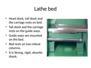
Lathe bed
• Headstock, tail stock and
the carriage rests on bed.
• Tail stock and the carriage
rests on the guide ways.
• Guide ways are mounted
on the bed.
• Bed rests on two robust
columns.
• It is Strong, rigid, absorbs
shock.
25.
Motors
• It Providesdrive for various mechanism
• It Has a cone pulley, called motor pulley
• Head stock pulley mounted on spindle gets
power from the motor pulley.
• Through cone pulley arrangement power is
given to the speed change gear box which
transmits power for the job rotation.
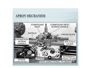
26.
chucks
• It isJob holding devices
• Two types: Three or
four jaw chucks.
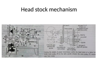
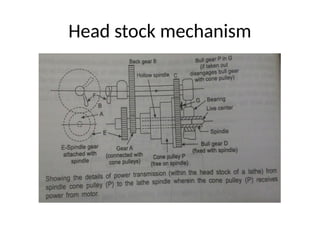
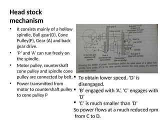
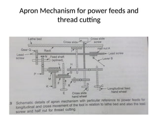
Head stock
mechanism
• Itconsists mainly of a hollow
spindle, Bull gear(D), Cone
Pulley(P), Gear (A) and back
gear drive.
• ‘P’ and ‘A’ can run freely on
the spindle.
• Motor pulley, countershaft
cone pulley and spindle cone
pulley are connected by belt.
• Power transmitted from
motor to countershaft pulley
to cone pulley P
To obtain lower speed, ‘D’ is
disengaged.
‘B’ engaged with ‘A’, ‘C’ engages with
‘D’
‘C’ is much smaller than ‘D’
So power flows at a much reduced rpm
from C to D.
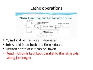
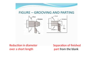
• Cylindrical barreduces in diameter
• Job is held into chuck and then rotated
• Desired depth of cut can be taken
• Feed motion is kept kept parallel to the lathe axis,
along job length
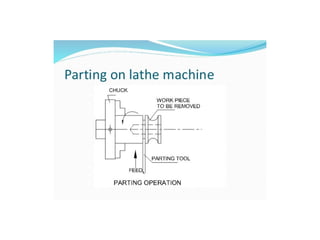
Lathe operations
32.
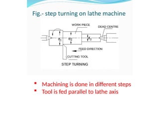
Machining isdone in different steps
Tool is fed parallel to lathe axis
33.
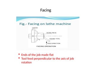
Ends ofthe job made flat
Tool feed perpendicular to the axis of job
rotation
Facing
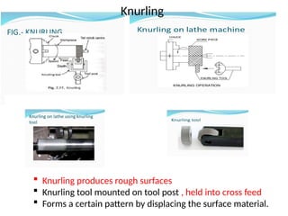
Knurling producesrough surfaces
Knurling tool mounted on tool post , held into cross feed
Forms a certain pattern by displacing the surface material.
Knurling
38.
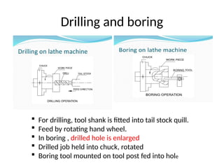
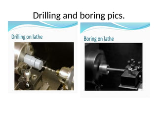
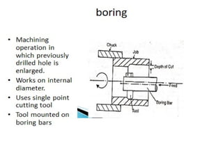
Drilling and boring
For drilling, tool shank is fitted into tail stock quill.
Feed by rotating hand wheel.
In boring , drilled hole is enlarged
Drilled job held into chuck, rotated
Boring tool mounted on tool post fed into hole
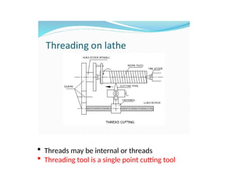
Threads maybe internal or threads
Threading tool is a single point cutting tool
48.
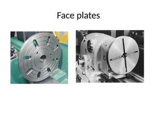
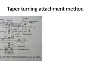
Lathe accessories andattachments
Accessories – work and tool holding & supporting devices
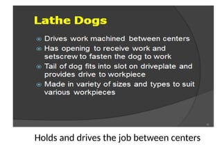
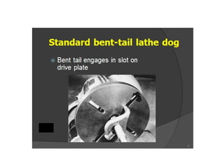
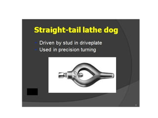
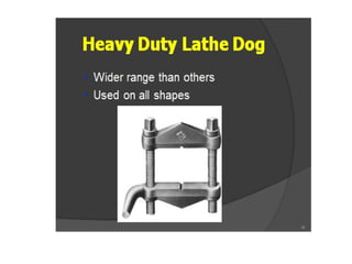
ex. Chucks, face plates, lathe centers, dog carriers,
mandrel, steady rest, follower rest, tool post etc
Attachments- devices performing special operations
Ex. Taper turning attachment, thread cutting attachment,
Gear cutting attachment etc.
49.
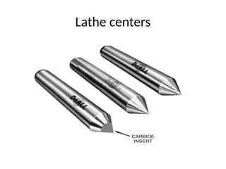
Lathe centers
• Usedto hold and rotate the job
• One center fitted into the spindle nose, called
live center.
• Other center into the quill of the tail stock,
called dead center.
• Dead center can be moved forward and can
be moved forward and clamped, it can be
retracted back for loosening the job.
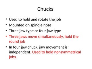
Chucks
• Used tohold and rotate the job
• Mounted on spindle nose
• Three jaw type or four jaw type
• Three jaws move simultaneously, hold the
round job
• In four jaw chuck, jaw movement is
independent. Used to hold nonsymmetrical
jobs.
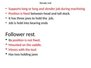
Steady rest
• Supportslong or long and slender job during machining
• Position is fixed between head and tail stock.
• It has three jaws to hold the job.
• Job is hold into bearing ends
Follower rest.
Its position is not fixed.
Mounted on the saddle.
Moves with the tool
Has two holding jaws
65.
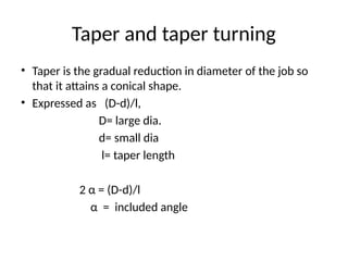
Taper and taperturning
• Taper is the gradual reduction in diameter of the job so
that it attains a conical shape.
• Expressed as (D-d)/l,
D= large dia.
d= small dia
l= taper length
2 α = (D-d)/l
α = included angle
66.
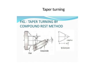
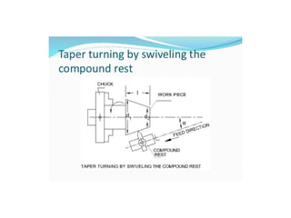
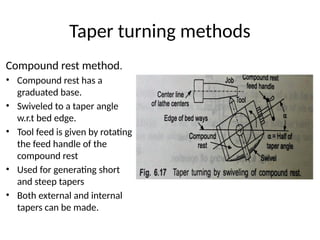
Taper turning methods
Compoundrest method.
• Compound rest has a
graduated base.
• Swiveled to a taper angle
w.r.t bed edge.
• Tool feed is given by rotating
the feed handle of the
compound rest
• Used for generating short
and steep tapers
• Both external and internal
tapers can be made.
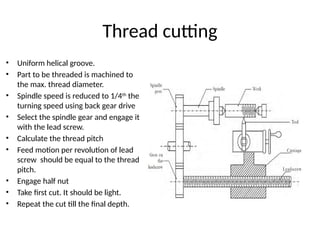
Thread cutting
• Uniformhelical groove.
• Part to be threaded is machined to
the max. thread diameter.
• Spindle speed is reduced to 1/4th
the
turning speed using back gear drive
• Select the spindle gear and engage it
with the lead screw.
• Calculate the thread pitch
• Feed motion per revolution of lead
screw should be equal to the thread
pitch.
• Engage half nut
• Take first cut. It should be light.
• Repeat the cut till the final depth.
69.
Design Considerations andGuidelines for
Turning Operations
• 1. part design should be such that its holding
and supporting should be easy. Proper holding
should be possible.
• 2.dimensional accuracy and surface finish
should be as large as permissible without
affecting the function.
• 3. sharp corners, tapers, steps and major
dimensional variations should be avoided.
70.
• 4. componentshould be of almost final size.
amount of material to removed should be
small.
5. Tool should be able to travel along job length
without obstruction.
6. Part should be such that commercially
available tools, inserts, tools holders should be
applicable.
7. Part should be machinable.
71.
Guidelines for turning
•Minimum tool overhang.
• Rigid support to the job.
• Machine should have high stiffness and high
damping capacity.
• Tool vibration and chatter should be
eliminated
72.
Chip collection systems
•1. by gravity fall on the conveyor belt.
• 2. dragging chips from the settling tank.
• 3. using augers with feed screws.
• 4. by using magnetic conveyors.
• By vacuum methods.
91.
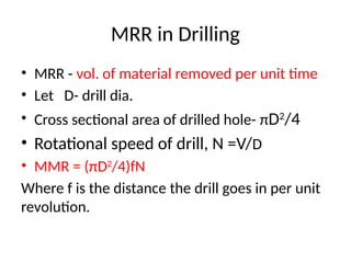
MRR in Drilling
•MRR - vol. of material removed per unit time
• Let D- drill dia.
• Cross sectional area of drilled hole- πD2
/4
• Rotational speed of drill, N =V/D
• MMR = (πD2
/4)fN
Where f is the distance the drill goes in per unit
revolution.
92.
Drilling practice
• Fixthe drill in drill chuck
• Drills tends to walk on the work surface in the
beginning
• Such lateral tool movement should be avoided
• Use tool guide, ex fixture or
• Use tool face having S- shape
93.
Design considerations fordrilling
1. Hole should come on the flat surface . Exiting
surface should be flat.
2. Interrupted hole surfaces should be
avoided(for tool life, vibrations, dimensional
accuracy).
3. Blind holes avoided. Thorough holes preferred.
4. Provide dimples or preholes to avoid drill walk
95.
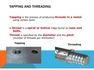
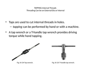
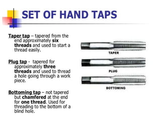
TAPPING-Internal Threads
Threading Canbe on External Dia or Internal
• Taps are used to cut internal threads in holes.
– tapping can be performed by hand or with a machine.
• A tap wrench or a T-handle tap wrench provides driving
torque while hand tapping.
Fig. B-134 Tap wrench. Fig. B-135 T-handle tap wrench.
96.
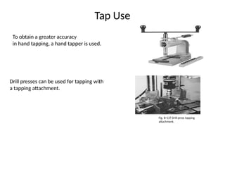
Tap Use
To obtaina greater accuracy
in hand tapping, a hand tapper is used.
Drill presses can be used for tapping with
a tapping attachment.
Fig. B-137 Drill press tapping
attachment.
97.
Thread Percentage andHole Strength
Thread strength depends on the work-piece material, percentage
of full thread used, and the length of the thread.
Percentage of thread produced is dependent on the diameter of
the drilled hole.
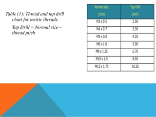
Tap drill charts give drill sizes to produce 75% thread.
Common practice is to have a bolt engage a tapped hole by 1 to 1-
1/2 times its diameter.
Threaded assemblies are usually designed so the
bolt breaks before the threaded hole strips.
98.
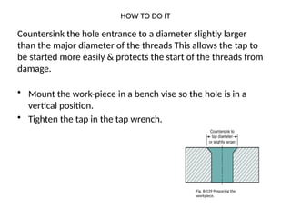
HOW TO DOIT
• Mount the work-piece in a bench vise so the hole is in a
vertical position.
• Tighten the tap in the tap wrench.
Countersink the hole entrance to a diameter slightly larger
than the major diameter of the threads This allows the tap to
be started more easily & protects the start of the threads from
damage.
Fig. B-139 Preparing the
workpiece.
99.
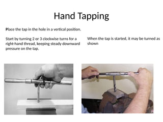
Hand Tapping
Place thetap in the hole in a vertical position.
Start by turning 2 or 3 clockwise turns for a
right-hand thread, keeping steady downward
pressure on the tap.
When the tap is started, it may be turned as
shown
100.
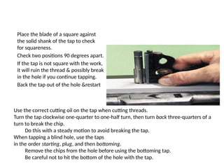
Place the bladeof a square against
the solid shank of the tap to check
for squareness.
Check two positions 90 degrees apart.
If the tap is not square with the work,
it will ruin the thread & possibly break
in the hole if you continue tapping.
Back the tap out of the hole &restart
Use the correct cutting oil on the tap when cutting threads.
Turn the tap clockwise one-quarter to one-half turn, then turn back three-quarters of a
turn to break the chip.
Do this with a steady motion to avoid breaking the tap.
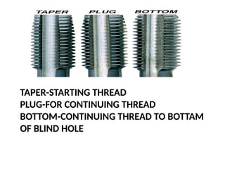
When tapping a blind hole, use the taps
in the order starting, plug, and then bottoming.
Remove the chips from the hole before using the bottoming tap.
Be careful not to hit the bottom of the hole with the tap.
101.
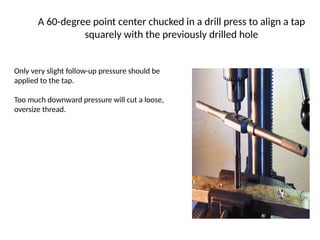
A 60-degree pointcenter chucked in a drill press to align a tap
squarely with the previously drilled hole
Only very slight follow-up pressure should be
applied to the tap.
Too much downward pressure will cut a loose,
oversize thread.