A tool that has a single point for cutting purpose is called single point cutting tool. It is generally used in the lathe machine, shaper machine etc. It is used to remove the materials from the workpiece.
Unit 2 Machinability, Cutting Fluids, Tool Life & Wear, Tool MaterialsMechbytes
Concept of machinability, machinability index, factors affecting machinability
Different mechanism of tool wear types of tool wear (crater, flank etc.), Measurement and control of tool wear
Concept of tool life, Taylor's tool life equation (including modified version)
Different tool materials and their applications including effect of tool coating
Introduction to economics of machining
Cutting fluids: types, properties, selection and application methods
Fundamentals of Metal cutting and Machining Processes
MACHINING OPERATIONS AND MACHINING TOOLS
Turning and Related Operations
Drilling and Related Operations
Milling
Machining Centers and Turning Centers
Other Machining Operations
High Speed Machining
This chapter aims to provide basic backgrounds of different types of machining processes and highlights on an understanding of important parameters which affects machining of metals with their chip removals.
Metal cutting or Machining is the process of producing workpiece by removing unwanted material from a block of metal. in the form of chips. This process is most important since almost all the products get their final shape and size by metal removal. either directly or indirectly.
The major drawback of the process is loss of material in the form of chips. In this chapter. we shall have a fundamental understanding of the basic metal process.
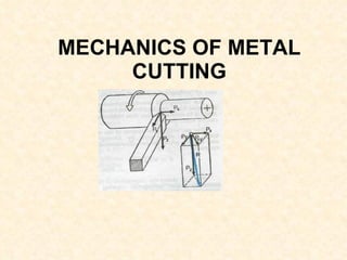
Theory of Metal cutting - Principles of Metal cutting, orthogonal and oblique cutting, Merchant circle diagram, cutting forces, power requirements, Economics of machining,problems
this presentation tries to explain the various heat zones that are developed during the metal cutting process. furthermore, how much heat is dissipated from the various zones. lastly the possible methods of temperature reduction in brief.
Dynamo meters are the electronic devices that are widely used to the purpose of force analysis in various field of operations. There is various types of dynamometers such as
Lathe tool dynamometer
Milling tool dynamometer
Drilling tool dynamometer
This presentation contains various aspects of metal cutting like mechanics of chip formation, single point cutting tool, chip breakers, types of chips,etc
One of the welding processes that used in Engineering field is the resistance welding. There are several types of welding processes similar to this, but resistance welding has its unique features.
Thanks for the colleagues who give this slides to publish.
a cutting tool or cutter is any tool that is used to remove material from the work piece by means of shear deformation. Cutting may be accomplished by single-point or multipoint tools. Single-point tools are used in turning, shaping, planing and similar operations, and remove material by means of one cutting edge. Milling and drilling tools are often multipoint tools. Grinding tools are also multipoint tools. Each grain of abrasive functions as a microscopic single-point cutting edge (although of high negative rake angle), and shears a tiny chip
Cutting power & Energy Consideration in metal cuttingDushyant Kalchuri
Cutting power is an important parameter, especially in the case of rough operations, as it makes it possible to:
select and invest in a machine with a power output suited to the operation being carried out
obtain the cutting conditions that allow the machine's power to be used in the most effective way possible, so as to ensure optimal material removal rate while taking into account the capacity of the tool being used.
this is 2nd presentation of manufacturing processes in this presentation we discuss in detail about the theory of metal cutting, machiening processes,cutters etc
Operation “Blue Star” is the only event in the history of Independent India where the state went into war with its own people. Even after about 40 years it is not clear if it was culmination of states anger over people of the region, a political game of power or start of dictatorial chapter in the democratic setup.
The people of Punjab felt alienated from main stream due to denial of their just demands during a long democratic struggle since independence. As it happen all over the word, it led to militant struggle with great loss of lives of military, police and civilian personnel. Killing of Indira Gandhi and massacre of innocent Sikhs in Delhi and other India cities was also associated with this movement.
This is a presentation by Dada Robert in a Your Skill Boost masterclass organised by the Excellence Foundation for South Sudan (EFSS) on Saturday, the 25th and Sunday, the 26th of May 2024.
He discussed the concept of quality improvement, emphasizing its applicability to various aspects of life, including personal, project, and program improvements. He defined quality as doing the right thing at the right time in the right way to achieve the best possible results and discussed the concept of the "gap" between what we know and what we do, and how this gap represents the areas we need to improve. He explained the scientific approach to quality improvement, which involves systematic performance analysis, testing and learning, and implementing change ideas. He also highlighted the importance of client focus and a team approach to quality improvement.
Read| The latest issue of The Challenger is here! We are thrilled to announce that our school paper has qualified for the NATIONAL SCHOOLS PRESS CONFERENCE (NSPC) 2024. Thank you for your unwavering support and trust. Dive into the stories that made us stand out!
How to Make a Field invisible in Odoo 17Celine George
It is possible to hide or invisible some fields in odoo. Commonly using “invisible” attribute in the field definition to invisible the fields. This slide will show how to make a field invisible in odoo 17.
How to Create Map Views in the Odoo 17 ERPCeline George
The map views are useful for providing a geographical representation of data. They allow users to visualize and analyze the data in a more intuitive manner.
4. Heat Generation Zones (Dependent on sharpness of tool) (Dependent on ) (Dependent on 10% 30% 60%
5. Tool Terminology Side relief angle Side cutting edge angle (SCEA) Clearance or end relief angle Back Rake (BR),+ Side Rake (SR), + End Cutting edge angle (ECEA) Nose Radius Turning Cutting edge Facing Cutting edge
12. ‘ Turning’ Forces For Orthogonal Model End view section 'A'-'A' Note: For the 2D Orthogonal Mechanistic Model we will ignore the radial component F t 'A' 'A' c F
13. ‘ Facing’ Forces For Orthogonal Model End view Note: For the 2D Orthogonal Mechanistic Model we will ignore the Longitudinal component
14.
15. Orthogonal Cutting Model (Simple 2D mechanistic model) Mechanism: Chips produced by the shearing process along the shear plane t 0 + Rake Angle Chip Workpiece Clearance Angle Shear Angle depth of cut Chip thickness Tool Velocity V tool t c
16. tool Cutting Ratio (or chip thicknes ratio) t c t o A B Chip Workpiece
17. Experimental Determination of Cutting Ratio Shear angle may be obtained either from photo-micrographs or assume volume continuity (no chip density change): i.e. Measure length of chips (easier than thickness) w t L 0 0 0 w c L c c t
18. Shear Plane Length and Angle or make an assumption, such as adjusts to minimize cutting force: (Merchant) t c t o A B Chip tool Workpiece
19. Velocities (2D Orthogonal Model) Velocity Diagram (Chip relative to workpiece) V = Chip Velocity (Chip relative to tool) Tool Workpiece Chip V = Cutting Velocity (Tool relative to workpiece) Shear Velocity c V s V V s V c
20. Cutting Forces ( 2D Orthogonal Cutting) Free Body Diagram Generally we know: Tool geometry & type Workpiece material and we wish to know: F = Cutting Force F = Thrust Force F = Friction Force N = Normal Force F = Shear Force F = Force Normal to Shear c t s n Tool Workpiece Chip Dynamometer R R R R F c F t s F F n N F
21. Force Circle Diagram (Merchants Circle) R F t F c Tool F N F s F n
27. Specific Cutting Energy (or Unit Power) Energy required to remove a unit volume of material (often quoted as a function of workpiece material, tool and process:
28. Specific Cutting Energy Decomposition 1. Shear Energy/unit volume (Us) (required for deformation in shear zone) 2. Friction Energy/unit volume (Uf) (expended as chip slides along rake face) 3. Chip curl energy/unit volume (Uc) (expended in curling the chip) 4. Kinetic Energy/unit volume (Um) (required to accelerate chip)
29. Specific Cutting Energy Relationship to Shear strength of Material SHEAR ENERGY / UNIT VOLUME FRICTION ENERGY / UNIT VOLUME APPROXIMATE TOTAL SPECIFIC CUTTING ENERGY
![Topics to be covered ,[object Object],[object Object],[object Object],[object Object],[object Object]](data:image/gif;base64,R0lGODlhAQABAIAAAAAAAP///yH5BAEAAAAALAAAAAABAAEAAAIBRAA7)