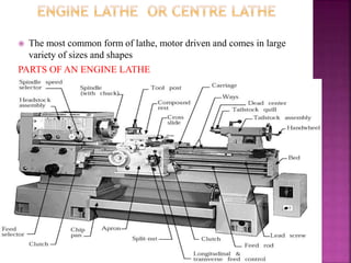
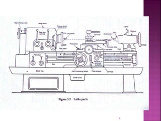
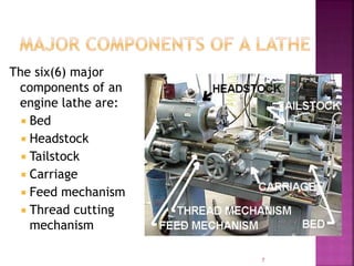
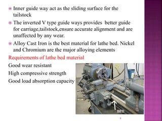
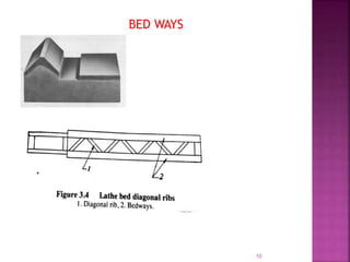
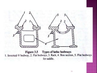
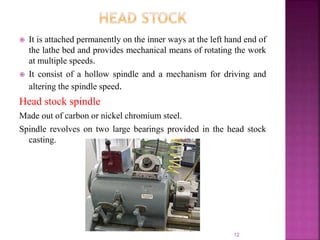
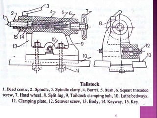
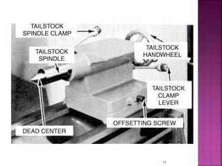
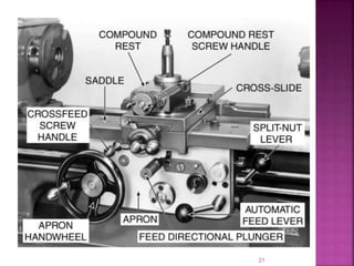
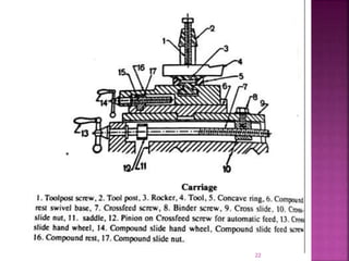
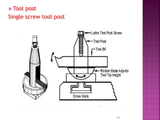
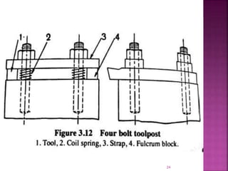
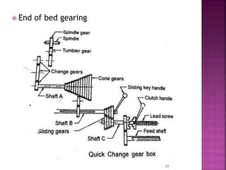
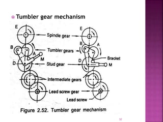
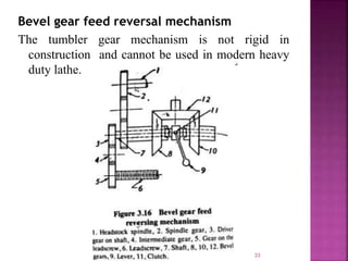
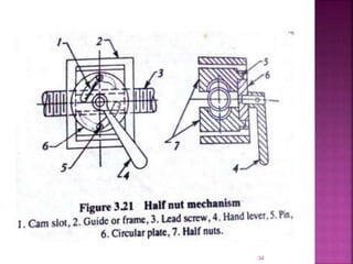
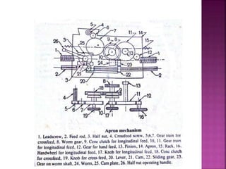
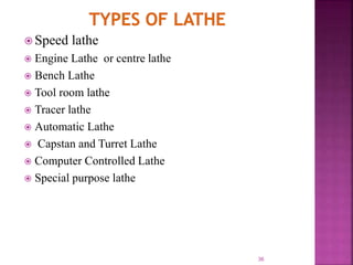
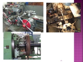
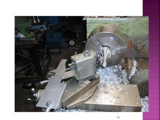
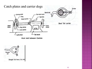
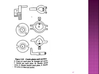
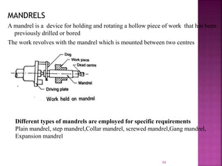
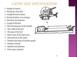
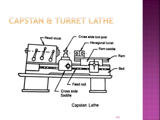
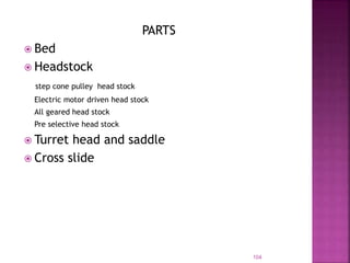
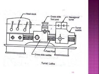
MACHINE TOOLS
Definition for Machine tool
A machine tool is a power driven device which is used
to produce jobs of desired size, shape and surface
finish by removing excess material from the
preformed blanks in the form of chips with the help
of cutting tools moved past the work surface(s).
Definition for Machining
It is the process of producing workpiece having desired
size, shape and surface finish by removing excess
material from the preformed blanks in the form of
chips .
2
The physical functions of a Machine Tool in
machining are:
 firmly holding the workpiece and the tool
 transmit motions to the tool and the work piece
 provide power to the tool-work pair for the machining
action.
 control of the machining parameters, i.e., speed, feed
and depth of cut.
3
 Lathe
 Shaper
 Milling machines
 Drilling machines
 Grinding machines
 Slotting machines
 Planing machines
 Boring machines
Lathe is a machine, which removes the metal from the workpiece to
the required shape &size
4
 The most common form of lathe, motor driven and comes in large
variety of sizes and shapes
PARTS OF AN ENGINE LATHE
5
6
The six(6) major
components of an
engine lathe are:
 Bed
 Headstock
 Tailstock
 Carriage
 Feed mechanism
 Thread cutting
mechanism
7
 The foundation of a lathe is the bed.
 Head stock and tailstock are located on either end of
the bed and carriage rest over the lathe bed and slides
on it
 In order to make rigid ribs are provided on the lathe
bed
 The bed provides the basic lathe rigidity and is the
primary source to the alignment of the other major
components of the lathe.
 On the top of the bed there are 2 set of
guideways(outer ways and innerways)
 Outer guide way provides sliding surface for the
carriage
8
 Inner guide way act as the sliding surface for the
tailstock
 The inverted V type guide ways provides better guide
for carriage,tailstock,ensure accurate alignment and are
unaffected by any wear.
 Alloy Cast Iron is the best material for lathe bed. Nickel
and Chromium are the major alloying elements
Requirements of lathe bed material
Good wear resistant
High compressive strength
Good load absorption capacity
9
10
BED WAYS
11
 It is attached permanently on the inner ways at the left hand end of
the lathe bed and provides mechanical means of rotating the work
at multiple speeds.
 It consist of a hollow spindle and a mechanism for driving and
altering the spindle speed.
Head stock spindle
Made out of carbon or nickel chromium steel.
Spindle revolves on two large bearings provided in the head stock
casting.
12
SPINDLE NOSES TYPES
Threaded type – most commonly used
Flanged type
13
14
15
Methods to vary the speed of the lathe spindle
1. By belt drive or cone pulley fitted on the
headstock spindle with or without back gear
arrangement
2. By all gear drive using sliding gears or
clutches
3. By variable speed motor
 Tail stock is located on the inner ways of the right hand
end of the bed.
Its functions are
 It supports the other end of the work when it is being
machined between centres.
 It holds the tool for performing operations such as
drilling, reaming, tapping etc
16
17
18
 The Carriage assembly is the work horse of the lathe. It is
composed of:
 Saddle
 Cross slide
 Compound rest
 Tool post
 Apron
A Saddle, which is an "H" shaped casting machined to fit the
"V"-ways of the bed and slides along the ways
It carries the Cross slide and tool post
Cross slide
We can move the cutting tool right angles to the lathe axis
19
Compound rest
Mounted on the top of the cross slide and has a circular base
graduated in degrees.
It is used for obtaining angular cuts and short tapers as well as
convenient positioning of the tool to the work.
There is no power feed to the compound rest.
Tool post
Located on the top of the compound rest to hold the tool and
enable it to be adjusted to a convenient working position
Common types of tool post are
Single screw tool post
Four bolt tool post
Open side tool post
Four way tool post
20
21
22
 Tool post
Single screw tool post
23
24
25
26
APRON
It is attached to the saddle and hangs over the front of the
bed
It contains gears,clutches,levers for operating the carriage
by hand and power feed.
The apron also contains friction clutches for automatic
feed
Apron mechanism makes longitudinal feed of the carriage
and cross feed of the cross slide be automatic
FEED mechanism
Longitudinal feed
Cross feed
Angular feed
27
Consist of the following units
End of bed gearing
Feed gear box
Feed rod and lead screw
Apron mechanism
28
 End of bed gearing
29
30
Feed gear box
Feed gear box or quick-change gear box is fitted
directly below the head stock assembly.
This gear box contains a number of different sizes of
gears which provides a means to change the rate of
feed, and the ratio between revolutions of head stock
spindle and the movement of the carriage for thread
cutting by altering the speed of rotation of lead screw
or feed rod
Feed rod
Feed rod is a long shaft that has the keyway extending
from feedbox across and in front of the bed.
Feed rod is used to move the carriage or cross slide for
turning ,boring, facing and all other operations except
thread cutting.
Lead screw
Lead screw is a long threaded shaft used as a master
screw and is used in case of thread cutting.
Reversal of feed
Tumbler gear mechanism
Bevel gear feed reversal mechanism
Tumbler gear mechanism
is used to change the direction of rotation of lead
screw and feed rod.
By engaging tumbler gear the carriage can be moved
automatically from tailstock end to head stock end
and vice versa.
During thread cutting this mechanism is used .
31
 Tumbler gear mechanism
32
Bevel gear feed reversal mechanism
The tumbler gear mechanism is not rigid in
construction and cannot be used in modern heavy
duty lathe.
33
34
35
 Speed lathe
 Engine Lathe or centre lathe
 Bench Lathe
 Tool room lathe
 Tracer lathe
 Automatic Lathe
 Capstan and Turret Lathe
 Computer Controlled Lathe
 Special purpose lathe
36
Types of lathe
Speed lathe
In construction and operation simplest of all types of
lathe. 2 to 3 spindle speeds are available. High spindle
speed from 1200- 3600 rpm
Engine Lathe or centre lathe
The most common form of lathe, motor driven and
comes in large variety of sizes and shapes.
Bench Lathe
A bench top model usually of low power used to make
precision machine small work pieces.
Tracer Lathe
a lathe that has the ability to follow a template to copy
a shape or contour.
37
Automatic Lathe
High speed, heavy duty, mass production lathes with automatic
control
Performs automatically all operations to finish the job
Changing of tools, speeds and feeds are done automatically
Machine repeats the cycles producing identical parts without an
operator after completing a job
Turret Lathe
A lathe which have multiple tools mounted on turret either
attached to the tailstock or the cross-slide, which allows for
quick changes in tooling and cutting operations.
Computer Controlled Lathe
A highly automated lathe, where both cutting, loading, tool
changing, and part unloading are automatically controlled by
computer coding.
38
39
Tool room lathe
Features similar to engine lathe
More accurately built and has wide range of spindle speeds –
very low to quite high upto 2500 rpm
Equipped with a chuck, taper turning attachment, collet
attachment, steady and follower rest etc.
Used for precision work on tools, dies, gauges where accuracy
is needed.
Costlier than engine lathe of the same size
Special purpose lathe
 Used for special purposes
 For jobs which cannot be machined on standard lathe
40
41
42
Accessories are used for holding and supporting the work or for holding the tool
Attachments are additional equipment used for specific purposes.
Different Accessories are on lathe are
 Centres
 Catch plates and carrier dogs
 chucks
 Collets
 Face plate
 Angle plate
 Mandrels
 Rests ( steady rest & follower rest)
Attachments are
 Grinding attachment
 Milling attachment
 Grinding attachment
 Gear cutting attachment
43
Work holding between centres
44
Centres
45
46
Catch plates and carrier dogs
47
 Chucks
A chuck is one of the most important device for holding and rotating
the work piece on lathe
Chuck is attached to the lathe spindle by means of bolt with back
plate screwed on to the spindle nose.
Different types of chucks are
 4 jaw chuck
 3 jaw chuck
 Air or hydraulic operated chuck
 Magnetic chuck
 Collet chuck
 Combination chuck
 Magnetic chuck
 Drill chuck
 Combination chuck
48
3 jaw chuck
49
4 jaw chuck
50
51
Air or hydraulic operated chuck Collet chuck
Collet chuck is used to hold small
workpieces
magnetic chuck
52
Thin jobs can be held by means of
magnetic chucks
Face plate & Angle plate
53
54
MANDRELS
A mandrel is a device for holding and rotating a hollow piece of work that has been
previously drilled or bored
The work revolves with the mandrel which is mounted between two centres
Different types of mandrels are employed for specific requirements
Plain mandrel, step mandrel,Collar mandrel, screwed mandrel,Gang mandrel,
Expansion mandrel
Plain mandrel Step mandrel
Collar mandrel screwed mandrel
55
 Gang mandrel Expansion mandrel
Cone Mandrel
56
57
Rests ( steady rest & follower rest)
58
59
60
61
62
63
64
65
66
67
68
Thread cutting mechanism
69
70
71
72
73
74
75
76
77
78
79
80
81
82
83
 Height of centres
 Swing dia. Over bed
 Length between centres
 Swing diameter over carriage.
 Maximun bar diameter.
 Length of the bed
 The bore diameter of the spindle
 The width of the bed
 The type of the bed
 Pitch value of the lead screw
 Horse power of the motor
 .Number and range of spindle speeds
 Number of feeds
 Spindle nose diameter
 Floor space required
84
Sensitive drilling machine
85
86
TYPES OF DRILLING MACHINE.
 Portable drilling machine
 Sensitive drilling machine
 Bench mounting and floor mounting
 Upright drilling machine(Round column and box column section)
 Radial drilling machine
 Plain, semi universal and universal
 Gang drilling machine
 Multiple spindle drilling machines.
 Automatic drilling machine
 Deep hole drilling machine(vertical and horizontal)
87
88
DRILLING MACHINE OPERATIONS
1. Drilling: it is an operation of producing a circular hole in a work piece
by forcing a drill in the work piece.
2. Boring: it is an operation of enlarging a hole that has already been
drilled. Single point cutting tool is used in boring.
3. Reaming: Reaming is done with reamers. It is done to generate the hole
of proper size and finish after drilling
4. Tapping: It is an operating of producing internal threads in a hole by
means of a tap.
5. Counter Boring: It is an operation of enlarging the entry of a drilled
hole to accommodate the bolt head etc. Counter boring tool does it.
6. Spot Facing: It is an operation done on the drilled hole to provide
smooth seat for bolt head.
7. Counter Sinking: It is an operation to bevel the top of a drilled hole for
making a conical seat. A counter sunk drill is used in this operation.
8.Trepanning
Trepanning is the operation of producing a hole in sheet metal by
removing metal along the circumference of a hollow cutting tool.
Trepanning operation is performed for producing large holes
89
Work holding devices on drilling machine
 T bolt and clamp
 Drill press vise
 Step block
 V block
 angle plate
 Drill jig
T bolt and clamp
90
91
Tool holding devices
 By directly fitting into spindle
 By a sleeve
 By a socket
 By chucks
 By special attachments
Tapping attachment
92
93
Drilling machine tools
Twist drill
Straight shank
Taper shank
Flat drill
Straight fluted drill
Taper shank core drill
Oil tube drill
Centre drill.
94
 Drilling Machine Tools---Standard twist drill nomenclatutre
95
Drilling Machine Tools---Standard twist drill nomenclatutre
96
AXIS: Imaginary straight line that forms the center line of the drill
BODY: Portion of the drill extending from its extreme point to the commencement of neck.
DRILL DIAMETER: The diameter over the margins of the drill measured at the point.
CHISEL EDGE: Edge formed by the intersection of flanks.
BODY DIAMETER CLEARANCE The portion of the body surface which is reduced in diameter to
provide diametral clearance.
CHISEL EDGE CORNER Corner formed by the intersection of a lip and the chisel edge..
FLUTE : Groove in the body of the drill which provides lip
FLANK: The surface on point which extends behind the lip to the following flute.
FACE : The portion of the flute surface adjacent to the lip on which the chip impinges
as it cut from the work.
HEEL : Edge formed by the intersection of flute surface and body clearance.
LAND : Cylindrically ground surface on the leading edge of the drill flutes.
LIP(CUTTING EDGE): Edge formed by the intersection of flank and face
POINT Sharpened end of the drill consisting all part of the drill which is sharpened to
produce lips,faces,flanks and chisel edge.
TANG: The flattened end of taper shank intended to fit into a drift slot in the spindle.
SHANK Part of the drill by which it is held and rotate
WEB: The central portion of the body that joins the lands. The extreme end of the web
forms the chisel edge on a two-flute drill
97
BACK TAPER: Slight decrease in diameter from point towards shank, in the
body of the drill.
FLUTE LENGTH: The axial length from the extreme end of the point to the
termination of the flute at the shank end of the body.
LEAD OF HELIX : The distance measured parallel to the drill axis between
the corresponding point on the leading edge of the flute in one complete turn
of the flute.
LIP LENGTH Minimum distance between Outer corner and the chisel edge
corner of the lip.
OVERALL LENGTH : The length over the extreme ends of the point and the
shank of the drill.
DRILL ANGLES
CHISEL EDGE ANGLE included angle between the chisel edge and lip as
viewed from the end of the drill
. Usual value of this is 120 deg to 135 deg.
HELIX ANGLE Angle formed by the leading edge of the land with a plane
having the axis of the drill.
If flute is right handed – the rake angle is positive .
If flute is left handed – the rake angle is negative
Value : 30 deg to 45 deg.
98
POINT ANGLE: Included angle between 2 lips projected upon a plane parallel to the drill
axis and parallel to the 2 cutting lips.
Point angle of standard twist drill is 118 deg.
LIP CLEARANCE ANGLE : angle formed by the flank and a plane right angles to the drill
axis.
lip clearance angle is usually 12 deg.
99
100
101
Designation of twist drill
eg . Parallel shank twist drill(long) 10.00-IS :599-CS-S-80
Drill materials
One piece construction : HSS or carbon steel
Two piece construction-
cutting portion :HSS
Shank portion :carbon steel
Cemented carbide tipped drills are also used in mass production
work
102
103
PARTS
 Bed
 Headstock
step cone pulley head stock
Electric motor driven head stock
All geared head stock
Pre selective head stock
 Turret head and saddle
 Cross slide
104
105
106
107
108
109
110
111
112
 traversing head shaper.mp4
113
114
115
116
117
118
 How Quick Return Mechanism Work! _Best 3D
Animation_ Crank & Slotted lever or
Whitworth Mechanism_.mp4
119
120
 crank and slotted link quick return
mechanism.mp4
121
122
123
124
125
126
 CLAMPING ON VICE
 CLAMPING DIRECTLY ON TABLE
USING T BOLT AND STRAP CLAMP
USING STRIP AND STOP PINS
USING A WEDGE STRIP AND STOP PIN
 CLAMPING ON AN ANGLE PLATE
 CLAMPING OVER A VEE BLOCK
 CLAMIG USING FIXTURES
127
128
129
130
131
 Machining horizontal surface
 Machining vertical surface
 Machining angular surface
 Cutting slot,grooves and keyways
 Machining splines and cutting gears
 Machining irregular surfaces
132
133
134
135
Shaper size specifications
•Length of stroke
•Ratio of cutting time to return time
•Power required (kW)
•Floor space required
•Weight of the machine
136
 Cutting speed
 Feed
 Depth of cut
137
138
139
140

Lathe( Machine Tools-KTU)

  • 1.
  • 2.
    Definition for Machinetool A machine tool is a power driven device which is used to produce jobs of desired size, shape and surface finish by removing excess material from the preformed blanks in the form of chips with the help of cutting tools moved past the work surface(s). Definition for Machining It is the process of producing workpiece having desired size, shape and surface finish by removing excess material from the preformed blanks in the form of chips . 2
  • 3.
    The physical functionsof a Machine Tool in machining are:  firmly holding the workpiece and the tool  transmit motions to the tool and the work piece  provide power to the tool-work pair for the machining action.  control of the machining parameters, i.e., speed, feed and depth of cut. 3
  • 4.
     Lathe  Shaper Milling machines  Drilling machines  Grinding machines  Slotting machines  Planing machines  Boring machines Lathe is a machine, which removes the metal from the workpiece to the required shape &size 4
  • 5.
     The mostcommon form of lathe, motor driven and comes in large variety of sizes and shapes PARTS OF AN ENGINE LATHE 5
  • 6.
  • 7.
    The six(6) major componentsof an engine lathe are:  Bed  Headstock  Tailstock  Carriage  Feed mechanism  Thread cutting mechanism 7
  • 8.
     The foundationof a lathe is the bed.  Head stock and tailstock are located on either end of the bed and carriage rest over the lathe bed and slides on it  In order to make rigid ribs are provided on the lathe bed  The bed provides the basic lathe rigidity and is the primary source to the alignment of the other major components of the lathe.  On the top of the bed there are 2 set of guideways(outer ways and innerways)  Outer guide way provides sliding surface for the carriage 8
  • 9.
     Inner guideway act as the sliding surface for the tailstock  The inverted V type guide ways provides better guide for carriage,tailstock,ensure accurate alignment and are unaffected by any wear.  Alloy Cast Iron is the best material for lathe bed. Nickel and Chromium are the major alloying elements Requirements of lathe bed material Good wear resistant High compressive strength Good load absorption capacity 9
  • 10.
  • 11.
  • 12.
     It isattached permanently on the inner ways at the left hand end of the lathe bed and provides mechanical means of rotating the work at multiple speeds.  It consist of a hollow spindle and a mechanism for driving and altering the spindle speed. Head stock spindle Made out of carbon or nickel chromium steel. Spindle revolves on two large bearings provided in the head stock casting. 12
  • 13.
    SPINDLE NOSES TYPES Threadedtype – most commonly used Flanged type 13
  • 14.
  • 15.
    15 Methods to varythe speed of the lathe spindle 1. By belt drive or cone pulley fitted on the headstock spindle with or without back gear arrangement 2. By all gear drive using sliding gears or clutches 3. By variable speed motor
  • 16.
     Tail stockis located on the inner ways of the right hand end of the bed. Its functions are  It supports the other end of the work when it is being machined between centres.  It holds the tool for performing operations such as drilling, reaming, tapping etc 16
  • 17.
  • 18.
  • 19.
     The Carriageassembly is the work horse of the lathe. It is composed of:  Saddle  Cross slide  Compound rest  Tool post  Apron A Saddle, which is an "H" shaped casting machined to fit the "V"-ways of the bed and slides along the ways It carries the Cross slide and tool post Cross slide We can move the cutting tool right angles to the lathe axis 19
  • 20.
    Compound rest Mounted onthe top of the cross slide and has a circular base graduated in degrees. It is used for obtaining angular cuts and short tapers as well as convenient positioning of the tool to the work. There is no power feed to the compound rest. Tool post Located on the top of the compound rest to hold the tool and enable it to be adjusted to a convenient working position Common types of tool post are Single screw tool post Four bolt tool post Open side tool post Four way tool post 20
  • 21.
  • 22.
  • 23.
     Tool post Singlescrew tool post 23
  • 24.
  • 25.
  • 26.
  • 27.
    APRON It is attachedto the saddle and hangs over the front of the bed It contains gears,clutches,levers for operating the carriage by hand and power feed. The apron also contains friction clutches for automatic feed Apron mechanism makes longitudinal feed of the carriage and cross feed of the cross slide be automatic FEED mechanism Longitudinal feed Cross feed Angular feed 27
  • 28.
    Consist of thefollowing units End of bed gearing Feed gear box Feed rod and lead screw Apron mechanism 28
  • 29.
     End ofbed gearing 29
  • 30.
    30 Feed gear box Feedgear box or quick-change gear box is fitted directly below the head stock assembly. This gear box contains a number of different sizes of gears which provides a means to change the rate of feed, and the ratio between revolutions of head stock spindle and the movement of the carriage for thread cutting by altering the speed of rotation of lead screw or feed rod Feed rod Feed rod is a long shaft that has the keyway extending from feedbox across and in front of the bed. Feed rod is used to move the carriage or cross slide for turning ,boring, facing and all other operations except thread cutting.
  • 31.
    Lead screw Lead screwis a long threaded shaft used as a master screw and is used in case of thread cutting. Reversal of feed Tumbler gear mechanism Bevel gear feed reversal mechanism Tumbler gear mechanism is used to change the direction of rotation of lead screw and feed rod. By engaging tumbler gear the carriage can be moved automatically from tailstock end to head stock end and vice versa. During thread cutting this mechanism is used . 31
  • 32.
     Tumbler gearmechanism 32
  • 33.
    Bevel gear feedreversal mechanism The tumbler gear mechanism is not rigid in construction and cannot be used in modern heavy duty lathe. 33
  • 34.
  • 35.
  • 36.
     Speed lathe Engine Lathe or centre lathe  Bench Lathe  Tool room lathe  Tracer lathe  Automatic Lathe  Capstan and Turret Lathe  Computer Controlled Lathe  Special purpose lathe 36
  • 37.
    Types of lathe Speedlathe In construction and operation simplest of all types of lathe. 2 to 3 spindle speeds are available. High spindle speed from 1200- 3600 rpm Engine Lathe or centre lathe The most common form of lathe, motor driven and comes in large variety of sizes and shapes. Bench Lathe A bench top model usually of low power used to make precision machine small work pieces. Tracer Lathe a lathe that has the ability to follow a template to copy a shape or contour. 37
  • 38.
    Automatic Lathe High speed,heavy duty, mass production lathes with automatic control Performs automatically all operations to finish the job Changing of tools, speeds and feeds are done automatically Machine repeats the cycles producing identical parts without an operator after completing a job Turret Lathe A lathe which have multiple tools mounted on turret either attached to the tailstock or the cross-slide, which allows for quick changes in tooling and cutting operations. Computer Controlled Lathe A highly automated lathe, where both cutting, loading, tool changing, and part unloading are automatically controlled by computer coding. 38
  • 39.
    39 Tool room lathe Featuressimilar to engine lathe More accurately built and has wide range of spindle speeds – very low to quite high upto 2500 rpm Equipped with a chuck, taper turning attachment, collet attachment, steady and follower rest etc. Used for precision work on tools, dies, gauges where accuracy is needed. Costlier than engine lathe of the same size Special purpose lathe  Used for special purposes  For jobs which cannot be machined on standard lathe
  • 40.
  • 41.
  • 42.
  • 43.
    Accessories are usedfor holding and supporting the work or for holding the tool Attachments are additional equipment used for specific purposes. Different Accessories are on lathe are  Centres  Catch plates and carrier dogs  chucks  Collets  Face plate  Angle plate  Mandrels  Rests ( steady rest & follower rest) Attachments are  Grinding attachment  Milling attachment  Grinding attachment  Gear cutting attachment 43
  • 44.
  • 45.
  • 46.
    46 Catch plates andcarrier dogs
  • 47.
  • 48.
     Chucks A chuckis one of the most important device for holding and rotating the work piece on lathe Chuck is attached to the lathe spindle by means of bolt with back plate screwed on to the spindle nose. Different types of chucks are  4 jaw chuck  3 jaw chuck  Air or hydraulic operated chuck  Magnetic chuck  Collet chuck  Combination chuck  Magnetic chuck  Drill chuck  Combination chuck 48
  • 49.
  • 50.
  • 51.
    51 Air or hydraulicoperated chuck Collet chuck Collet chuck is used to hold small workpieces
  • 52.
    magnetic chuck 52 Thin jobscan be held by means of magnetic chucks
  • 53.
    Face plate &Angle plate 53
  • 54.
    54 MANDRELS A mandrel isa device for holding and rotating a hollow piece of work that has been previously drilled or bored The work revolves with the mandrel which is mounted between two centres Different types of mandrels are employed for specific requirements Plain mandrel, step mandrel,Collar mandrel, screwed mandrel,Gang mandrel, Expansion mandrel
  • 55.
    Plain mandrel Stepmandrel Collar mandrel screwed mandrel 55
  • 56.
     Gang mandrelExpansion mandrel Cone Mandrel 56
  • 57.
    57 Rests ( steadyrest & follower rest)
  • 58.
  • 59.
  • 60.
  • 61.
  • 62.
  • 63.
  • 64.
  • 65.
  • 66.
  • 67.
  • 68.
  • 69.
  • 70.
  • 71.
  • 72.
  • 73.
  • 74.
  • 75.
  • 76.
  • 77.
  • 78.
  • 79.
  • 80.
  • 81.
  • 82.
  • 83.
  • 84.
     Height ofcentres  Swing dia. Over bed  Length between centres  Swing diameter over carriage.  Maximun bar diameter.  Length of the bed  The bore diameter of the spindle  The width of the bed  The type of the bed  Pitch value of the lead screw  Horse power of the motor  .Number and range of spindle speeds  Number of feeds  Spindle nose diameter  Floor space required 84
  • 85.
  • 86.
    86 TYPES OF DRILLINGMACHINE.  Portable drilling machine  Sensitive drilling machine  Bench mounting and floor mounting  Upright drilling machine(Round column and box column section)  Radial drilling machine  Plain, semi universal and universal  Gang drilling machine  Multiple spindle drilling machines.  Automatic drilling machine  Deep hole drilling machine(vertical and horizontal)
  • 87.
  • 88.
    88 DRILLING MACHINE OPERATIONS 1.Drilling: it is an operation of producing a circular hole in a work piece by forcing a drill in the work piece. 2. Boring: it is an operation of enlarging a hole that has already been drilled. Single point cutting tool is used in boring. 3. Reaming: Reaming is done with reamers. It is done to generate the hole of proper size and finish after drilling 4. Tapping: It is an operating of producing internal threads in a hole by means of a tap. 5. Counter Boring: It is an operation of enlarging the entry of a drilled hole to accommodate the bolt head etc. Counter boring tool does it. 6. Spot Facing: It is an operation done on the drilled hole to provide smooth seat for bolt head. 7. Counter Sinking: It is an operation to bevel the top of a drilled hole for making a conical seat. A counter sunk drill is used in this operation. 8.Trepanning Trepanning is the operation of producing a hole in sheet metal by removing metal along the circumference of a hollow cutting tool. Trepanning operation is performed for producing large holes
  • 89.
  • 90.
    Work holding deviceson drilling machine  T bolt and clamp  Drill press vise  Step block  V block  angle plate  Drill jig T bolt and clamp 90
  • 91.
  • 92.
    Tool holding devices By directly fitting into spindle  By a sleeve  By a socket  By chucks  By special attachments Tapping attachment 92
  • 93.
  • 94.
    Drilling machine tools Twistdrill Straight shank Taper shank Flat drill Straight fluted drill Taper shank core drill Oil tube drill Centre drill. 94
  • 95.
     Drilling MachineTools---Standard twist drill nomenclatutre 95
  • 96.
    Drilling Machine Tools---Standardtwist drill nomenclatutre 96
  • 97.
    AXIS: Imaginary straightline that forms the center line of the drill BODY: Portion of the drill extending from its extreme point to the commencement of neck. DRILL DIAMETER: The diameter over the margins of the drill measured at the point. CHISEL EDGE: Edge formed by the intersection of flanks. BODY DIAMETER CLEARANCE The portion of the body surface which is reduced in diameter to provide diametral clearance. CHISEL EDGE CORNER Corner formed by the intersection of a lip and the chisel edge.. FLUTE : Groove in the body of the drill which provides lip FLANK: The surface on point which extends behind the lip to the following flute. FACE : The portion of the flute surface adjacent to the lip on which the chip impinges as it cut from the work. HEEL : Edge formed by the intersection of flute surface and body clearance. LAND : Cylindrically ground surface on the leading edge of the drill flutes. LIP(CUTTING EDGE): Edge formed by the intersection of flank and face POINT Sharpened end of the drill consisting all part of the drill which is sharpened to produce lips,faces,flanks and chisel edge. TANG: The flattened end of taper shank intended to fit into a drift slot in the spindle. SHANK Part of the drill by which it is held and rotate WEB: The central portion of the body that joins the lands. The extreme end of the web forms the chisel edge on a two-flute drill 97
  • 98.
    BACK TAPER: Slightdecrease in diameter from point towards shank, in the body of the drill. FLUTE LENGTH: The axial length from the extreme end of the point to the termination of the flute at the shank end of the body. LEAD OF HELIX : The distance measured parallel to the drill axis between the corresponding point on the leading edge of the flute in one complete turn of the flute. LIP LENGTH Minimum distance between Outer corner and the chisel edge corner of the lip. OVERALL LENGTH : The length over the extreme ends of the point and the shank of the drill. DRILL ANGLES CHISEL EDGE ANGLE included angle between the chisel edge and lip as viewed from the end of the drill . Usual value of this is 120 deg to 135 deg. HELIX ANGLE Angle formed by the leading edge of the land with a plane having the axis of the drill. If flute is right handed – the rake angle is positive . If flute is left handed – the rake angle is negative Value : 30 deg to 45 deg. 98
  • 99.
    POINT ANGLE: Includedangle between 2 lips projected upon a plane parallel to the drill axis and parallel to the 2 cutting lips. Point angle of standard twist drill is 118 deg. LIP CLEARANCE ANGLE : angle formed by the flank and a plane right angles to the drill axis. lip clearance angle is usually 12 deg. 99
  • 100.
  • 101.
  • 102.
    Designation of twistdrill eg . Parallel shank twist drill(long) 10.00-IS :599-CS-S-80 Drill materials One piece construction : HSS or carbon steel Two piece construction- cutting portion :HSS Shank portion :carbon steel Cemented carbide tipped drills are also used in mass production work 102
  • 103.
  • 104.
    PARTS  Bed  Headstock stepcone pulley head stock Electric motor driven head stock All geared head stock Pre selective head stock  Turret head and saddle  Cross slide 104
  • 105.
  • 106.
  • 107.
  • 108.
  • 109.
  • 110.
  • 111.
  • 112.
  • 113.
     traversing headshaper.mp4 113
  • 114.
  • 115.
  • 116.
  • 117.
  • 118.
    118  How QuickReturn Mechanism Work! _Best 3D Animation_ Crank & Slotted lever or Whitworth Mechanism_.mp4
  • 119.
  • 120.
  • 121.
     crank andslotted link quick return mechanism.mp4 121
  • 122.
  • 123.
  • 124.
  • 125.
  • 126.
  • 127.
     CLAMPING ONVICE  CLAMPING DIRECTLY ON TABLE USING T BOLT AND STRAP CLAMP USING STRIP AND STOP PINS USING A WEDGE STRIP AND STOP PIN  CLAMPING ON AN ANGLE PLATE  CLAMPING OVER A VEE BLOCK  CLAMIG USING FIXTURES 127
  • 128.
  • 129.
  • 130.
  • 131.
  • 132.
     Machining horizontalsurface  Machining vertical surface  Machining angular surface  Cutting slot,grooves and keyways  Machining splines and cutting gears  Machining irregular surfaces 132
  • 133.
  • 134.
  • 135.
  • 136.
    Shaper size specifications •Lengthof stroke •Ratio of cutting time to return time •Power required (kW) •Floor space required •Weight of the machine 136
  • 137.
     Cutting speed Feed  Depth of cut 137
  • 138.
  • 139.
  • 140.