Downloaded 468 times


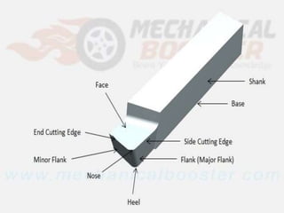
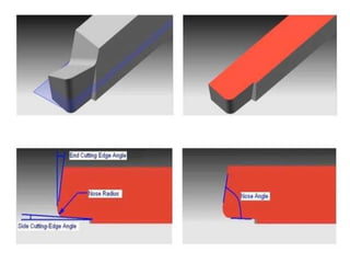


This document describes the key components and geometry of a single point cutting tool. A single point cutting tool has a shank that fits into the tool holder, a face along which chips slide upwards, and two cutting edges - a side cutting edge and an end cutting edge where material is removed. It also has flank surfaces below the cutting edges and a nose or cutting point where the edges intersect. The document outlines the various angles of a single point cutting tool, including the end cutting edge angle, side cutting edge angle, back rake angle, and relief angles, which are important for tool function. Tool shape is specified using a signature that lists the numerical values of these angles and the nose radius.


