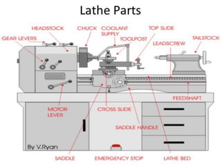
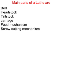
WORKING PRINCIPLE OF LATHE MACHINE
The Lathe is a machine tool which holds the
workpiece between two rigid and strong supports
called centers or in a chuck or in face plate which
revolves.
The cutting tool is held and fed against the revolving
work. Cutting tool fed either parallel or at right
angles to the axis of work piece
Component Description
Centre Lathe
Main parts of a Lathe are
Bed
Headstock
Tailstock
carriage
Feed mechanism
Screw cutting mechanism
BED
Lathe Bed
• Heavy, rugged casting, made from cast iron or
nickel cast iron alloy.
• Made to support working parts of lathe
It supports head stock, tail stock and carriage
• On top section are machined ways
–Guide and align major parts of lathe
HEADSTOCK
HEADSTOCK
Clamped on left-hand end of bed
• Headstock spindle
–Hollow cylindrical shaft supported by bearings
• Provides drive through gears to workholding
devices
– Live center, faceplate, or chuck fitted to spindle
nose to hold and drive work
• Driven by stepped pulley or transmission gears
TAILSTOCK
Tailstock
• Upper and lower tailstock castings
• Adjusted for taper or parallel turning by two
screws set in base
• Tailstock clamp locks tailstock in any position
along bed of lathe
• Tailstock spindle has internal taper to receive
dead center
–Provides support for right-hand end of work
Carriage
• Used to move cutting tool along lathe bed
• Consists of three main parts
–Saddle
• H-shaped casting mounted on top of lathe ways,
provides means of mounting cross-slide and apron
– Cross-slide
–Apron
Cross-slide
• Mounted on top of saddle
• Provides manual or automatic cross movement
for cutting tool
• Compound rest (fitted on top of cross slide)
–Used to support cutting tool
–Swiveled to any angle for taper-turning
–Has graduated collar that ensure accurate
cutting-tool settings (.001 in.) (also cross-slide)
Cross slide
Fitted on the saddle
Moves on the cutting tool at right angles to lathe
bed
TOP slide
Fitted to top of cross slide
Carries tool post and cutting tool
Can rotate to any angle
Is used to turn tapers
Feed mechanism
Three types of feed
Longitudinal
Cross
Angular
Apron
• Fastened to saddle
• Houses gears and mechanism required to move
carriage or cross-slide automatically
•Locking-off lever inside apron prevents engaging
split-nut lever and automatic feed lever at same
time
•Apron hand wheel turned manually to move
carriage along lathe bed
Cutting Tools:
High speed steel,ceramic and tungsten carbide etc
Specifications of Lathe
1) a) Height of centers
b)type of bed(straight , semi gap, or gap)
c) center distance
2. a)swing over bed
b)swing over cross slide
c) swing in gap
d) gap in front of face place
3. a) spindle speeds range
b) spindle nose
c) spindle bore
d) taper nose
4) a)Metric thread piches
b)lead screw pitch
c)longitudinal feeds
d)cross feeds
5) a) cross slide travel
b)top slide travel
c) tool selection
6) a)tailstock sleeve travel
b)taper in sleeve bore
7) Motor horsepower and RPM
8) shipping dimensions ---length*width*height*weight
• Height of center
• Length between the centers
• Length of bed
• The swing diameter over bed
• The swing diameter over
carriage
• Maximum diameter of bar
• Spindle speed, motor hp
Lathe Specifications
1.Length between the centers
It is the measure of the maximum length of the work piece that
can be fixed between the lathe centers
2. Height of the centers
It is the distance between the lathe axis and the lathe bed
3. Swing diameter over the bed
It is the maximum diameter of the workpiece that
can be turned on a lathe without hitting the lathe bed
4. Swing diameter over the carriage
It is the maximum diameter of the work piece that
can be turned on a lathe with out hitting the carriage
5. Maximum bar diameter
It is the maximum diameter of the work piece that can be
passed through the hole in the head stock
CLASSIFICATION OF LATHE MACHINE
Speed Lathe
Engine lathe
Bench Lathe
Tool room Lathe
Capstain & turret Lathe
Special purpose Lathe
Automatic Lathe
SPEED LATHE
It has no feed box, lead screw or conventional type
of carriage.
The tool is mounted on the adjustable slide and is
fed into the work by hand control
SPEED LATHE
Due to high speed of spindle it is called”Speed Lathe”
Speed of spindle:1200 to 3600 rpm
It is mainly used for metal spinning, polishing etc.
Centre Lathe
In starting it was driven by steam engine, so it is
called as Engine
It is not production Lathe, found in tool rooms and
job shops
Primarily for single piece or short runs
Types:
1) Belt driven lathe
2) Individual motor driven Lathe
3) Gear head drive Lathe
Operated Manually
Bench Lathe
It is small sized engine lathe mounted on bench
A bench top model usually of low power used to
make precision machine small work pieces.
Tool room Lathe
This lathe has features similar to an engine lathe
but it is much accurately built.
It has a wide range of spindle speeds ranging from
a very low to a quite high speed upto 2500 rpm
Tool room Lathe
It is used for production of small and precision
works like tools, gauges, fixtures and accurate
parts in tool room.
Different speeds can be achieved
Costly as compared to a small size engine lathe
Capstain and Turret Lathe
Modified Engine Lathe
Capstan lathes are used in mass production
used for light duty workpieces.
Turret lathes are used in mass production and
for heavy duty work pieces.
No tailstock.
Instead of tailstock hexagonal turret is used.
No time waste for resetting of tools.
Capstain and Turret Lathe
Special purpose Lathe
Conventional programmable lathe.
Operated as standard lathe to automatically repeat
machining operations.
Computerized numerically controlled lathes.
Cutting tool movements controlled by computer
controlled program to perform sequence of
operations automatically.
Computer controlled Lathe (CNC Lathe)
Special purpose Lathe
Constructed for special purposes and for jobs
which can not be accommodated or conveniently
machined on a standard lathe
Special purpose Lathe
1. The wheel lathe is made for finishing and turning
the tread on rail road car and locomotive wheels
2. The gap bed lathe, in which a section of the bed
adjacent to the headstock is removable, is used
to swing extra large diameter pieces
1. The T-Lathe is used for machining of rotors for
jet engines.The bed of this lathe has t-shape
2.Duplicating Lathe is one for duplicating the shape
of a flat or round template on to the job
Automatic Lathe
A lathe in which the work piece is cut
automatically and removed without use of an
operator.
Cutting operations are automatically controlled
by a sequence of some form.
1. Tracer Lathe: It has the ability to follow a
template to copy a shape or contour
Divided into two categories
Work holding, supporting and driving devices
Lathe centers, chucks, faceplates
Mandrels, steady and follower
rests
Lathe dogs, drive plates
Half center is used as a dead center in the tailstock
where facing is to be performed.
Half center
The cut away portion of the center faces the
cutting tool and provides the necessary clearance
for the tool when facing the surface immediately
around the drilled center in the workpiece.
Magnetic Chucks
• Used to hold iron or steel parts that are too thin or
may be damaged if held in conventional chuck
• Fitted to an adapter mounted on headstock spindle
• Used only for light cuts and for special grinding
applications
Lathe Dogs
• Drives work machined between centers
• Has opening to receive work and set screw
to fasten the dog to work.
• Tail of dog fits in to slot on drive plate and
provides drive to work piece
• Made in variety of sizes and types to suit
various work pieces
Work Held Between Centre
Types of Lathe Dogs
• Standard bent-tail lathe dog
– Most commonly used for round
workpieces
– Available with square-headless
setscrews
• Straight-tail lathe dog
–Driven by stud in drive plate
–Used in precision turning
• Safety clamp lathe dog
– Used to hold variety of work
– Wide range of adjustment
• Clamp lathe dog
– Wider range than others
– Used on all shapes
Faceplates
Workpiece
Faceplates
• Used to hold work too large or shaped so it
cannot be held in chuck or between centers
• Usually equipped with several slots to permit
use of bolts to secure work
Angle plate used so axis of workpiece may
be aligned with lathe centers
• Counter balance fastened to faceplate when work
mounted off center
– Prevent imbalance and resultant vibrations
Used to support long work held in chuck or between
lathe centers
Located and aligned by ways of the lathe
Positioned at any point along lathe bed
Steady Rest
Mounted on saddle
Travels with carriage to prevent work from springing up
and away from cutting tool
Cutting tool generally positioned just ahead of
follower rest
Provide smooth bearing surface for two jaws of
follower rest
Holds internally machined workpiece between
centers so further machining operations are
concentric with bore
Plain mandrel
Expanding mandrel
Gang mandrel
stub mandrel
Mandrels
Workpiece (job) with a hole
Workpiece Mandrel
Mandrels:
• is a cylindrical bar with centre hole at each end. It is
used to hold hollow work pieces to machine their
external surface.
• The work revolves with the mandrel which is mounted
between the centres of the lathe.
Gang Mandrels
Threaded stub mandrels are used for machining the
outside surfaces of parts that are threaded in the bore.
Stub Mandrels
Cutting-Tool-Holding Devices
• Available in three styles
– Left-hand offset
– Right-hand offset
– Straight
Left-Hand Offset Toolholder
• Offset to the right
• Designed for machining work cutting right to left
Straight Tool holder
• Used for taking cuts in either direction and
for general machining operations
Carbide Toolholder
• Has square hole parallel to base of tool
holder to accommodate carbide-tipped tool
bits
Threading Toolholder
• Has accurately ground 60º angle
• Only top of cutting surface sharpened when
becomes dull
Boring Tool holders
–Light boring tool holder
• Used for small holes and light cuts
–Medium boring tool holder
• Suitable for heavier cuts
Turning Operations
• Machine Tool – LATHE
• Job (workpiece) – rotary motion
• Tool – linear motions
Cylindrical and flat surfaces
Setting the tool height
• The cutting tool on
the lathe must be
set to the exact
centre of the work-
piece
• The centre of the
tailstock is used to
guide to the correct
height
Some Typical Lathe Jobs
Turning/Drilling/Grooving/
Threading/Knurling/Facing...
Operations on Lathe
• Turning
• Facing
• knurling
• Grooving
• Parting
• Chamfering
• Taper turning
• Drilling
• Threading
Turning: to remove material from the outside diameter of a
workpiece to obtain a finished surface.
Facing: to produce a flat surface at the end of the workpiece or
for making face grooves.
Boring: to enlarge a hole or cylindrical cavity made by a previous
process or to produce circular internal grooves.
Drilling: to produce a hole on the work piece.
Reaming: to finishing the drilled hole.
Threading: to produce external or internal threads on the work
piece.
Knurling: to produce a regularly shaped roughness on the
workpiece.
LATHE OPERATIONS
Turning
Cylindrical job
Turning: to remove material from the outside diameter of
a workpiece to obtain a finished surface.
Lathe operations
Facing off
Parallel Turning
Parallel Turning
Parallel Turning
• The tool moved parallel to the work and cylindrical
shapes are formed also known as sliding
Parallel Turning
• The operator can Parallel turn the work on
the lathe manually or use the automatic
traverse option
Turning ..
Cylindrical job
Cutting
speed
Chip
Workpiece
Depth of cut (d)
Depth of cut
Tool
Feed
Chuck
N
Machined
surface
Turning ..
• Excess Material is removed to
reduce Diameter
• Cutting Tool: Turning Tool
a depth of cut of 1 mm will
reduce diameter by 2 mm
Facing
Flat Surface/Reduce length
Depth of
cut
Feed
Workpiece
Chuck
Cutting
speed
Tool
d
Machined
Face
Facing
• The tool is moved
at right angles to
the work using
the cross slide
• Flat surfaces are
produced
Facing
To produce a flat surface at the end of the workpiece or
for making face grooves.
Facing ..
• machine end of job  Flat surface or to
Reduce Length of Job
• Turning Tool
• Feed: in direction perpendicular to workpiece
axis
–Length of Tool Travel = radius of workpiece
• Depth of Cut: in direction parallel to workpiece
axis
Eccentric Turning
Axis of job
Axis
Eccentric peg
(to be turned)
4-jaw
chuck
Cutting
speed
Knurling
• Produce rough textured surface
– For Decorative and/or Functional Purpose
• Knurling Tool
Knurling
• A knurling tool is used to press a pattern onto a
round section.
• The pattern is normally used as a grip for a handle.
• This provide a grip for the round part
e.g. Screwdriver
Knurling
Knurling
Knurling tool
Tool post
Feed
Cutting
speed
Movement
for depth
Knurled surface
Grooving
• Produces a Groove on workpiece
• Shape of tool  shape of groove
• Carried out using Grooving Tool 
A form tool
• Also called Form Turning
Grooving ..
Shape produced
by form tool Groove
Grooving
tool
Feed or
depth of cut
Form tool
Parting
• Cutting workpiece into Two
• Similar to grooving
• Parting Tool
• Hogging – tool rides over – at slow feed
• Coolant use
Parting ..
Feed
Parting tool
Chamfering
Chamfering tool
Feed
Chamfer
Chamfering
 Beveling sharp machined edges
 Similar to form turning
 Chamfering tool – 45°
 To
• Avoid Sharp Edges
• Make Assembly Easier
• Improve Aesthetics
Screw-cutting on the lathe
• Lathes are also
used to cut threads
in round bars
• These threads take
up different profiles
e.g iso (60°) ACME
etc.
• These threads can
be seen on bench
vices, lathes etc.
LATHE OPERATIONS
.
Producing a
Cylindrical Surface
Taper Turning
Producing a Flat Surface
Drilling on a Lathe
Parting Off / Under Cutting
Radius Turning Attachment
Taper Turning
• tan  = (D1-D2) / 2L
 C
B
A L
D
90°
 2
D1
Taper turning methods in lathe machine
1. Form tool method
2. Tailstock set over method
3. Compound rest method
Taper turning by combining feeds
4. Taper turning attachment method
Taper Turning ..
By Form Tool

Taper
Workpiece
Straight
cutting edge
Direction
of feed
Form
tool
Taper Turning by using form tool method
Shape of the tool is remain same as the shape of the
component to be produced.
Accuracy of taper produce depends on accuracy of
taper present on tool
Width of tool must be greater than or equal to the length
of workpiece to be taper turned.
Maximum length of component which can be taper
turned is 20 mm only
Only external taper turning is possible.
Taper turning by swiveling the compound rest
Taper Turning ,,
By Compound Rest
Face plate
Dog

Tail stock quill
Tail stock
Mandrel
Direction of feed
Compound rest
Slide
Compound rest
Hand crank
Tool post &
Tool holder
Cross slide
The compound rest has a circular base graduated in
degrees, which can be swiveled at any angle.
While turning a taper, the base of compound rest is
swiveled through an angle equal to the half taper angle.
The tool is then fed by hand.
Once the compound rest is set at the desired half taper
angle, rotation of the compound slide screw will cause
the tool to be fed at that angle and generate a
corresponding taper.
This method is limited to turn a short but steep taper
owing to the limited movement of the cross slide.
But a small taper may also be turned. The compound
rest may be swiveled at 45 degree on turn a steep taper.
Taper turning by a taper attachment
The principle of turning taper by a taper attachment is to
guide the tool in a straight path set at an angle to the
axis of rotation of the work piece, while the work is being
revolved between centers of lathe axis.
A taper turning attachment consists essentially of a
bracket which is attached to the rear end of the lathe
bed and supports a guide bar pivoted at the centers. The
bar having graduations in degrees may be swiveled on
either side of the zero graduation and is set at the
desired angle with the lathe axis
When the taper turning attachment is used, the cross
slide is first made free from the lead screw by removing
the binder screw. The rear end the cross slide is then
tightened with the guide block by means of a bolt.
When the longitudinal feed is engaged, the tool mounted
on the cross slide will follow the angular path, as the
guide block will slide on the gear bar at an angle to the
lathe axis.
The required depth of cut is given by the compound slide
which is placed at right angles to the lathe axis.
The guide bar must be set at half taper angle and the
taper on the work must be converted in degrees. The
maximum angle through which the guide bar may be
swiveled is 10 degree to 12 degree on either side of the
centre line.
If the diameters D,d and the length L of the taper are
specified, the angle of swiveling the guide bar can be
determined from equation
The advantage of using a taper turning attachment are
The alignment of live and dead centers being not
disturbed, both straight and taper turning may be
performed on a work piece in one setting without much
loss of time.
once the taper is set, any length of a piece of work may
be turned with in its limit.
very steep taper on a long work piece may be turned,
which cannot be done by any other method.
Accurate taper on a large number of work pieces may
be turned.
Internal tapers can be turned with ease.
Taper turning by combining feeds
Taper turning by combining feeds is a more specialized
method of turning taper.
In certain lathes both longitudinal and cross feeds may
be engaged simultaneously causing the tool to follow a
diagonal path which is the resultant of the magnitude of
the two feeds.
Tail stock off-set
Tailstock set over method
when the angle of taper is very small this method will be
employed.
The work piece be placed in the live center and dead
center.
The tailstock will be moved in a cross wise, that is
perpendicular to the lathe axis by turning the set over
method.
The job is inclined to the required angle. When the work
piece rotates the tool is moved parallel to the lathe axis.
So that the taper will be generated on the work piece.
Operating/Cutting Conditions
1. Cutting Speed v
2. Feed f
3. Depth of Cut d
Workpiece
Tool
Chip
Tool post
S
peripheral
speed (m/min)
N (rev/min)
D
© rkm2003
Operating Conditions
Workpiece
Tool
Chip
Tool post
S
peripheral
speed
(m/min)
N (rev/min)
D
N
D
S
speed
peripheral
D





rotation
1
in
travel
tool
relative
© rkm2003
Cutting Speed
The Peripheral Speed of Workpiece past
the Cutting Tool
=Cutting Speed
m/min
1000
N
D
v


D – Diameter (mm)
N – Revolutions per Minute (rpm)
© rkm2003
Feed
f – the distance the tool advances for
every rotation of workpiece (mm/rev)
f
Feed
D
D 2
1
© rkm2003
Depth of Cut
perpendicular distance between
machined surface and uncut surface of
the Workpiece
d = (D1 – D2)/2 (mm)
d Depth
of Cut
D
D 2
1
© rkm2003
3 Operating Conditions
Chip
Machined
surface
Workpiece
Depth of cut
Tool
Chuck
N
Feed (f )
Cutting speed
Depth of cut (d)
© rkm2003
Selection of ..
 Workpiece Material
 Tool Material
 Tool signature
 Surface Finish
 Accuracy
 Capability of Machine Tool
© rkm2003
Material Removal Rate
MRR
Volume of material removed in one
revolution MRR =  D d f mm3
• Job makes N revolutions/min
MRR =  D d f N (mm3/min)
 In terms of v MRR is given by
MRR = 1000 v d f (mm3/min)
© rkm2003
MRR
dimensional consistency by
substituting the units
MRR: D d f N 
(mm)(mm)(mm/rev)(rev/min)
= mm3/min
Machining Time
Turning Time
• Job length Lj mm
• Feed f mm/rev
• Job speed N rpm
• f N mm/min
min
N
f
L
t
j

Manufacturing Time
Manufacturing Time
= Machining Time + Setup Time + Moving
Time + Waiting Time
Machining time:
min
N
f
L
t
j

t = 500 / (0.7191)
= 3.74 minutes
Thread Cutting
The process of thread cutting is to produce a
helical groove on a cylindrical surface by
feeding the tool longitudinally
1. The job is revolved between center or by a chuck. The
longitudinal feed should be equal to the pitch of the
thread to be cut per revolution of the work piece.
2. The carriage should be moved longitudinally obtaining
feed through the lead-screw of the lathe.
3. A definite ratio between the longitudinal feed and
rotation of the headstock spindle should be found out.
Suitable gears with required number of teeth should be
mounted on the spindle and the lead screw.
4. A proper thread cutting tool is selected
according to the shape of the thread
The definite relative rotary and linear motion between
job and cutting tool is achieved by locking or engaging
a carriage motion with lead screw and nut mechanism
and fixing a gear ratio between head stock spindle
and lead screw.
To make or cut threads, the cutting tool is brought to
the start of job and a small depth of cut is given to
cutting tool using cross slide.
5. The position of the tumbler gears are adjusted
according to the type of the thread
6. Suitable spindle speed is selected and it is obtained
through back gears.
7. After the process of thread cutting is over, the thread
is checked by suitable gauges.

LatheMachine_2019-20.pptx

  • 3.
    WORKING PRINCIPLE OFLATHE MACHINE The Lathe is a machine tool which holds the workpiece between two rigid and strong supports called centers or in a chuck or in face plate which revolves. The cutting tool is held and fed against the revolving work. Cutting tool fed either parallel or at right angles to the axis of work piece
  • 5.
  • 6.
  • 9.
    Main parts ofa Lathe are Bed Headstock Tailstock carriage Feed mechanism Screw cutting mechanism
  • 10.
  • 11.
    Lathe Bed • Heavy,rugged casting, made from cast iron or nickel cast iron alloy. • Made to support working parts of lathe It supports head stock, tail stock and carriage • On top section are machined ways –Guide and align major parts of lathe
  • 12.
  • 13.
    HEADSTOCK Clamped on left-handend of bed • Headstock spindle –Hollow cylindrical shaft supported by bearings • Provides drive through gears to workholding devices – Live center, faceplate, or chuck fitted to spindle nose to hold and drive work • Driven by stepped pulley or transmission gears
  • 15.
  • 16.
    Tailstock • Upper andlower tailstock castings • Adjusted for taper or parallel turning by two screws set in base • Tailstock clamp locks tailstock in any position along bed of lathe • Tailstock spindle has internal taper to receive dead center –Provides support for right-hand end of work
  • 19.
    Carriage • Used tomove cutting tool along lathe bed • Consists of three main parts –Saddle • H-shaped casting mounted on top of lathe ways, provides means of mounting cross-slide and apron – Cross-slide –Apron
  • 21.
    Cross-slide • Mounted ontop of saddle • Provides manual or automatic cross movement for cutting tool • Compound rest (fitted on top of cross slide) –Used to support cutting tool –Swiveled to any angle for taper-turning –Has graduated collar that ensure accurate cutting-tool settings (.001 in.) (also cross-slide)
  • 24.
    Cross slide Fitted onthe saddle Moves on the cutting tool at right angles to lathe bed
  • 25.
    TOP slide Fitted totop of cross slide Carries tool post and cutting tool Can rotate to any angle Is used to turn tapers
  • 30.
    Feed mechanism Three typesof feed Longitudinal Cross Angular
  • 32.
    Apron • Fastened tosaddle • Houses gears and mechanism required to move carriage or cross-slide automatically •Locking-off lever inside apron prevents engaging split-nut lever and automatic feed lever at same time •Apron hand wheel turned manually to move carriage along lathe bed
  • 35.
    Cutting Tools: High speedsteel,ceramic and tungsten carbide etc
  • 39.
    Specifications of Lathe 1)a) Height of centers b)type of bed(straight , semi gap, or gap) c) center distance 2. a)swing over bed b)swing over cross slide c) swing in gap d) gap in front of face place 3. a) spindle speeds range b) spindle nose c) spindle bore d) taper nose
  • 40.
    4) a)Metric threadpiches b)lead screw pitch c)longitudinal feeds d)cross feeds 5) a) cross slide travel b)top slide travel c) tool selection 6) a)tailstock sleeve travel b)taper in sleeve bore 7) Motor horsepower and RPM 8) shipping dimensions ---length*width*height*weight
  • 42.
    • Height ofcenter • Length between the centers • Length of bed • The swing diameter over bed • The swing diameter over carriage • Maximum diameter of bar • Spindle speed, motor hp Lathe Specifications
  • 43.
    1.Length between thecenters It is the measure of the maximum length of the work piece that can be fixed between the lathe centers
  • 45.
    2. Height ofthe centers It is the distance between the lathe axis and the lathe bed
  • 47.
    3. Swing diameterover the bed It is the maximum diameter of the workpiece that can be turned on a lathe without hitting the lathe bed
  • 49.
    4. Swing diameterover the carriage It is the maximum diameter of the work piece that can be turned on a lathe with out hitting the carriage
  • 51.
    5. Maximum bardiameter It is the maximum diameter of the work piece that can be passed through the hole in the head stock
  • 53.
    CLASSIFICATION OF LATHEMACHINE Speed Lathe Engine lathe Bench Lathe Tool room Lathe Capstain & turret Lathe Special purpose Lathe Automatic Lathe
  • 55.
    SPEED LATHE It hasno feed box, lead screw or conventional type of carriage. The tool is mounted on the adjustable slide and is fed into the work by hand control
  • 56.
    SPEED LATHE Due tohigh speed of spindle it is called”Speed Lathe” Speed of spindle:1200 to 3600 rpm It is mainly used for metal spinning, polishing etc.
  • 58.
    Centre Lathe In startingit was driven by steam engine, so it is called as Engine It is not production Lathe, found in tool rooms and job shops Primarily for single piece or short runs Types: 1) Belt driven lathe 2) Individual motor driven Lathe 3) Gear head drive Lathe Operated Manually
  • 59.
    Bench Lathe It issmall sized engine lathe mounted on bench A bench top model usually of low power used to make precision machine small work pieces.
  • 60.
    Tool room Lathe Thislathe has features similar to an engine lathe but it is much accurately built. It has a wide range of spindle speeds ranging from a very low to a quite high speed upto 2500 rpm
  • 61.
    Tool room Lathe Itis used for production of small and precision works like tools, gauges, fixtures and accurate parts in tool room. Different speeds can be achieved Costly as compared to a small size engine lathe
  • 62.
    Capstain and TurretLathe Modified Engine Lathe Capstan lathes are used in mass production used for light duty workpieces. Turret lathes are used in mass production and for heavy duty work pieces. No tailstock. Instead of tailstock hexagonal turret is used. No time waste for resetting of tools.
  • 63.
  • 64.
    Special purpose Lathe Conventionalprogrammable lathe. Operated as standard lathe to automatically repeat machining operations. Computerized numerically controlled lathes. Cutting tool movements controlled by computer controlled program to perform sequence of operations automatically.
  • 65.
  • 66.
    Special purpose Lathe Constructedfor special purposes and for jobs which can not be accommodated or conveniently machined on a standard lathe
  • 67.
    Special purpose Lathe 1.The wheel lathe is made for finishing and turning the tread on rail road car and locomotive wheels 2. The gap bed lathe, in which a section of the bed adjacent to the headstock is removable, is used to swing extra large diameter pieces
  • 68.
    1. The T-Latheis used for machining of rotors for jet engines.The bed of this lathe has t-shape 2.Duplicating Lathe is one for duplicating the shape of a flat or round template on to the job
  • 69.
    Automatic Lathe A lathein which the work piece is cut automatically and removed without use of an operator. Cutting operations are automatically controlled by a sequence of some form.
  • 70.
    1. Tracer Lathe:It has the ability to follow a template to copy a shape or contour
  • 71.
    Divided into twocategories Work holding, supporting and driving devices Lathe centers, chucks, faceplates Mandrels, steady and follower rests Lathe dogs, drive plates
  • 78.
    Half center isused as a dead center in the tailstock where facing is to be performed. Half center
  • 80.
    The cut awayportion of the center faces the cutting tool and provides the necessary clearance for the tool when facing the surface immediately around the drilled center in the workpiece.
  • 88.
    Magnetic Chucks • Usedto hold iron or steel parts that are too thin or may be damaged if held in conventional chuck • Fitted to an adapter mounted on headstock spindle • Used only for light cuts and for special grinding applications
  • 89.
    Lathe Dogs • Driveswork machined between centers • Has opening to receive work and set screw to fasten the dog to work. • Tail of dog fits in to slot on drive plate and provides drive to work piece • Made in variety of sizes and types to suit various work pieces
  • 90.
  • 91.
    Types of LatheDogs • Standard bent-tail lathe dog – Most commonly used for round workpieces – Available with square-headless setscrews
  • 92.
    • Straight-tail lathedog –Driven by stud in drive plate –Used in precision turning
  • 93.
    • Safety clamplathe dog – Used to hold variety of work – Wide range of adjustment
  • 94.
    • Clamp lathedog – Wider range than others – Used on all shapes
  • 96.
  • 98.
    Faceplates • Used tohold work too large or shaped so it cannot be held in chuck or between centers • Usually equipped with several slots to permit use of bolts to secure work Angle plate used so axis of workpiece may be aligned with lathe centers
  • 99.
    • Counter balancefastened to faceplate when work mounted off center – Prevent imbalance and resultant vibrations
  • 101.
    Used to supportlong work held in chuck or between lathe centers Located and aligned by ways of the lathe Positioned at any point along lathe bed
  • 103.
  • 104.
    Mounted on saddle Travelswith carriage to prevent work from springing up and away from cutting tool Cutting tool generally positioned just ahead of follower rest Provide smooth bearing surface for two jaws of follower rest
  • 106.
    Holds internally machinedworkpiece between centers so further machining operations are concentric with bore Plain mandrel Expanding mandrel Gang mandrel stub mandrel
  • 107.
    Mandrels Workpiece (job) witha hole Workpiece Mandrel
  • 109.
    Mandrels: • is acylindrical bar with centre hole at each end. It is used to hold hollow work pieces to machine their external surface. • The work revolves with the mandrel which is mounted between the centres of the lathe.
  • 111.
  • 112.
    Threaded stub mandrelsare used for machining the outside surfaces of parts that are threaded in the bore. Stub Mandrels
  • 113.
    Cutting-Tool-Holding Devices • Availablein three styles – Left-hand offset – Right-hand offset – Straight
  • 114.
    Left-Hand Offset Toolholder •Offset to the right • Designed for machining work cutting right to left
  • 115.
    Straight Tool holder •Used for taking cuts in either direction and for general machining operations
  • 116.
    Carbide Toolholder • Hassquare hole parallel to base of tool holder to accommodate carbide-tipped tool bits
  • 117.
    Threading Toolholder • Hasaccurately ground 60º angle • Only top of cutting surface sharpened when becomes dull
  • 118.
    Boring Tool holders –Lightboring tool holder • Used for small holes and light cuts –Medium boring tool holder • Suitable for heavier cuts
  • 119.
    Turning Operations • MachineTool – LATHE • Job (workpiece) – rotary motion • Tool – linear motions Cylindrical and flat surfaces
  • 120.
    Setting the toolheight • The cutting tool on the lathe must be set to the exact centre of the work- piece • The centre of the tailstock is used to guide to the correct height
  • 121.
    Some Typical LatheJobs Turning/Drilling/Grooving/ Threading/Knurling/Facing...
  • 122.
    Operations on Lathe •Turning • Facing • knurling • Grooving • Parting • Chamfering • Taper turning • Drilling • Threading
  • 123.
    Turning: to removematerial from the outside diameter of a workpiece to obtain a finished surface. Facing: to produce a flat surface at the end of the workpiece or for making face grooves. Boring: to enlarge a hole or cylindrical cavity made by a previous process or to produce circular internal grooves. Drilling: to produce a hole on the work piece. Reaming: to finishing the drilled hole. Threading: to produce external or internal threads on the work piece. Knurling: to produce a regularly shaped roughness on the workpiece. LATHE OPERATIONS
  • 124.
  • 125.
    Turning: to removematerial from the outside diameter of a workpiece to obtain a finished surface.
  • 126.
    Lathe operations Facing off ParallelTurning Parallel Turning
  • 127.
    Parallel Turning • Thetool moved parallel to the work and cylindrical shapes are formed also known as sliding
  • 128.
    Parallel Turning • Theoperator can Parallel turn the work on the lathe manually or use the automatic traverse option
  • 129.
    Turning .. Cylindrical job Cutting speed Chip Workpiece Depthof cut (d) Depth of cut Tool Feed Chuck N Machined surface
  • 130.
    Turning .. • ExcessMaterial is removed to reduce Diameter • Cutting Tool: Turning Tool a depth of cut of 1 mm will reduce diameter by 2 mm
  • 131.
    Facing Flat Surface/Reduce length Depthof cut Feed Workpiece Chuck Cutting speed Tool d Machined Face
  • 132.
    Facing • The toolis moved at right angles to the work using the cross slide • Flat surfaces are produced
  • 133.
    Facing To produce aflat surface at the end of the workpiece or for making face grooves.
  • 134.
    Facing .. • machineend of job  Flat surface or to Reduce Length of Job • Turning Tool • Feed: in direction perpendicular to workpiece axis –Length of Tool Travel = radius of workpiece • Depth of Cut: in direction parallel to workpiece axis
  • 135.
    Eccentric Turning Axis ofjob Axis Eccentric peg (to be turned) 4-jaw chuck Cutting speed
  • 136.
    Knurling • Produce roughtextured surface – For Decorative and/or Functional Purpose • Knurling Tool
  • 137.
    Knurling • A knurlingtool is used to press a pattern onto a round section. • The pattern is normally used as a grip for a handle. • This provide a grip for the round part e.g. Screwdriver
  • 138.
  • 139.
  • 140.
    Grooving • Produces aGroove on workpiece • Shape of tool  shape of groove • Carried out using Grooving Tool  A form tool • Also called Form Turning
  • 141.
    Grooving .. Shape produced byform tool Groove Grooving tool Feed or depth of cut Form tool
  • 142.
    Parting • Cutting workpieceinto Two • Similar to grooving • Parting Tool • Hogging – tool rides over – at slow feed • Coolant use
  • 143.
  • 144.
  • 145.
    Chamfering  Beveling sharpmachined edges  Similar to form turning  Chamfering tool – 45°  To • Avoid Sharp Edges • Make Assembly Easier • Improve Aesthetics
  • 146.
    Screw-cutting on thelathe • Lathes are also used to cut threads in round bars • These threads take up different profiles e.g iso (60°) ACME etc. • These threads can be seen on bench vices, lathes etc.
  • 147.
    LATHE OPERATIONS . Producing a CylindricalSurface Taper Turning Producing a Flat Surface
  • 148.
    Drilling on aLathe Parting Off / Under Cutting Radius Turning Attachment
  • 149.
    Taper Turning • tan = (D1-D2) / 2L  C B A L D 90°  2 D1
  • 150.
    Taper turning methodsin lathe machine 1. Form tool method 2. Tailstock set over method 3. Compound rest method Taper turning by combining feeds 4. Taper turning attachment method
  • 151.
    Taper Turning .. ByForm Tool  Taper Workpiece Straight cutting edge Direction of feed Form tool
  • 152.
    Taper Turning byusing form tool method
  • 153.
    Shape of thetool is remain same as the shape of the component to be produced. Accuracy of taper produce depends on accuracy of taper present on tool Width of tool must be greater than or equal to the length of workpiece to be taper turned. Maximum length of component which can be taper turned is 20 mm only Only external taper turning is possible.
  • 154.
    Taper turning byswiveling the compound rest
  • 155.
    Taper Turning ,, ByCompound Rest Face plate Dog  Tail stock quill Tail stock Mandrel Direction of feed Compound rest Slide Compound rest Hand crank Tool post & Tool holder Cross slide
  • 156.
    The compound resthas a circular base graduated in degrees, which can be swiveled at any angle. While turning a taper, the base of compound rest is swiveled through an angle equal to the half taper angle. The tool is then fed by hand. Once the compound rest is set at the desired half taper angle, rotation of the compound slide screw will cause the tool to be fed at that angle and generate a corresponding taper.
  • 157.
    This method islimited to turn a short but steep taper owing to the limited movement of the cross slide. But a small taper may also be turned. The compound rest may be swiveled at 45 degree on turn a steep taper.
  • 158.
    Taper turning bya taper attachment
  • 159.
    The principle ofturning taper by a taper attachment is to guide the tool in a straight path set at an angle to the axis of rotation of the work piece, while the work is being revolved between centers of lathe axis. A taper turning attachment consists essentially of a bracket which is attached to the rear end of the lathe bed and supports a guide bar pivoted at the centers. The bar having graduations in degrees may be swiveled on either side of the zero graduation and is set at the desired angle with the lathe axis
  • 160.
    When the taperturning attachment is used, the cross slide is first made free from the lead screw by removing the binder screw. The rear end the cross slide is then tightened with the guide block by means of a bolt. When the longitudinal feed is engaged, the tool mounted on the cross slide will follow the angular path, as the guide block will slide on the gear bar at an angle to the lathe axis. The required depth of cut is given by the compound slide which is placed at right angles to the lathe axis.
  • 161.
    The guide barmust be set at half taper angle and the taper on the work must be converted in degrees. The maximum angle through which the guide bar may be swiveled is 10 degree to 12 degree on either side of the centre line. If the diameters D,d and the length L of the taper are specified, the angle of swiveling the guide bar can be determined from equation
  • 162.
    The advantage ofusing a taper turning attachment are The alignment of live and dead centers being not disturbed, both straight and taper turning may be performed on a work piece in one setting without much loss of time. once the taper is set, any length of a piece of work may be turned with in its limit. very steep taper on a long work piece may be turned, which cannot be done by any other method. Accurate taper on a large number of work pieces may be turned. Internal tapers can be turned with ease.
  • 163.
    Taper turning bycombining feeds Taper turning by combining feeds is a more specialized method of turning taper. In certain lathes both longitudinal and cross feeds may be engaged simultaneously causing the tool to follow a diagonal path which is the resultant of the magnitude of the two feeds.
  • 165.
  • 166.
    Tailstock set overmethod when the angle of taper is very small this method will be employed. The work piece be placed in the live center and dead center. The tailstock will be moved in a cross wise, that is perpendicular to the lathe axis by turning the set over method. The job is inclined to the required angle. When the work piece rotates the tool is moved parallel to the lathe axis. So that the taper will be generated on the work piece.
  • 167.
    Operating/Cutting Conditions 1. CuttingSpeed v 2. Feed f 3. Depth of Cut d Workpiece Tool Chip Tool post S peripheral speed (m/min) N (rev/min) D
  • 168.
    © rkm2003 Operating Conditions Workpiece Tool Chip Toolpost S peripheral speed (m/min) N (rev/min) D N D S speed peripheral D      rotation 1 in travel tool relative
  • 169.
    © rkm2003 Cutting Speed ThePeripheral Speed of Workpiece past the Cutting Tool =Cutting Speed m/min 1000 N D v   D – Diameter (mm) N – Revolutions per Minute (rpm)
  • 170.
    © rkm2003 Feed f –the distance the tool advances for every rotation of workpiece (mm/rev) f Feed D D 2 1
  • 171.
    © rkm2003 Depth ofCut perpendicular distance between machined surface and uncut surface of the Workpiece d = (D1 – D2)/2 (mm) d Depth of Cut D D 2 1
  • 172.
    © rkm2003 3 OperatingConditions Chip Machined surface Workpiece Depth of cut Tool Chuck N Feed (f ) Cutting speed Depth of cut (d)
  • 173.
    © rkm2003 Selection of..  Workpiece Material  Tool Material  Tool signature  Surface Finish  Accuracy  Capability of Machine Tool
  • 174.
    © rkm2003 Material RemovalRate MRR Volume of material removed in one revolution MRR =  D d f mm3 • Job makes N revolutions/min MRR =  D d f N (mm3/min)  In terms of v MRR is given by MRR = 1000 v d f (mm3/min)
  • 175.
    © rkm2003 MRR dimensional consistencyby substituting the units MRR: D d f N  (mm)(mm)(mm/rev)(rev/min) = mm3/min
  • 176.
    Machining Time Turning Time •Job length Lj mm • Feed f mm/rev • Job speed N rpm • f N mm/min min N f L t j 
  • 177.
    Manufacturing Time Manufacturing Time =Machining Time + Setup Time + Moving Time + Waiting Time
  • 178.
    Machining time: min N f L t j  t =500 / (0.7191) = 3.74 minutes
  • 179.
    Thread Cutting The processof thread cutting is to produce a helical groove on a cylindrical surface by feeding the tool longitudinally
  • 182.
    1. The jobis revolved between center or by a chuck. The longitudinal feed should be equal to the pitch of the thread to be cut per revolution of the work piece. 2. The carriage should be moved longitudinally obtaining feed through the lead-screw of the lathe.
  • 183.
    3. A definiteratio between the longitudinal feed and rotation of the headstock spindle should be found out. Suitable gears with required number of teeth should be mounted on the spindle and the lead screw. 4. A proper thread cutting tool is selected according to the shape of the thread
  • 184.
    The definite relativerotary and linear motion between job and cutting tool is achieved by locking or engaging a carriage motion with lead screw and nut mechanism and fixing a gear ratio between head stock spindle and lead screw. To make or cut threads, the cutting tool is brought to the start of job and a small depth of cut is given to cutting tool using cross slide.
  • 185.
    5. The positionof the tumbler gears are adjusted according to the type of the thread 6. Suitable spindle speed is selected and it is obtained through back gears. 7. After the process of thread cutting is over, the thread is checked by suitable gauges.