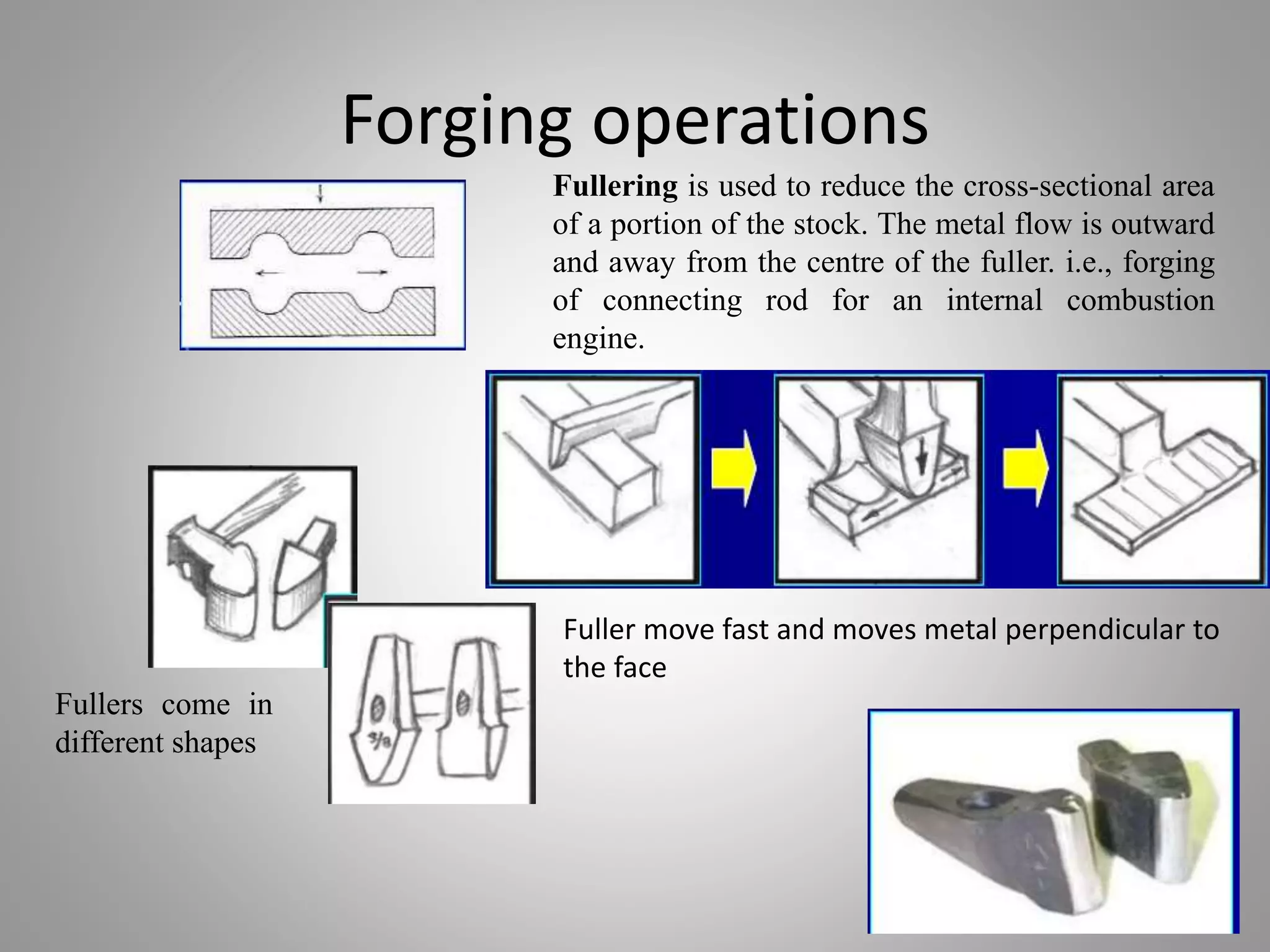
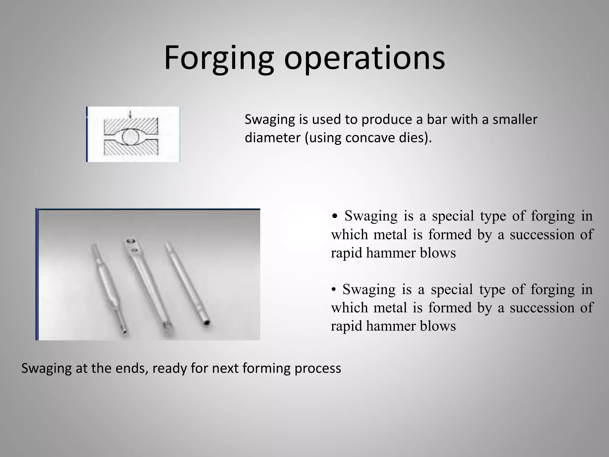
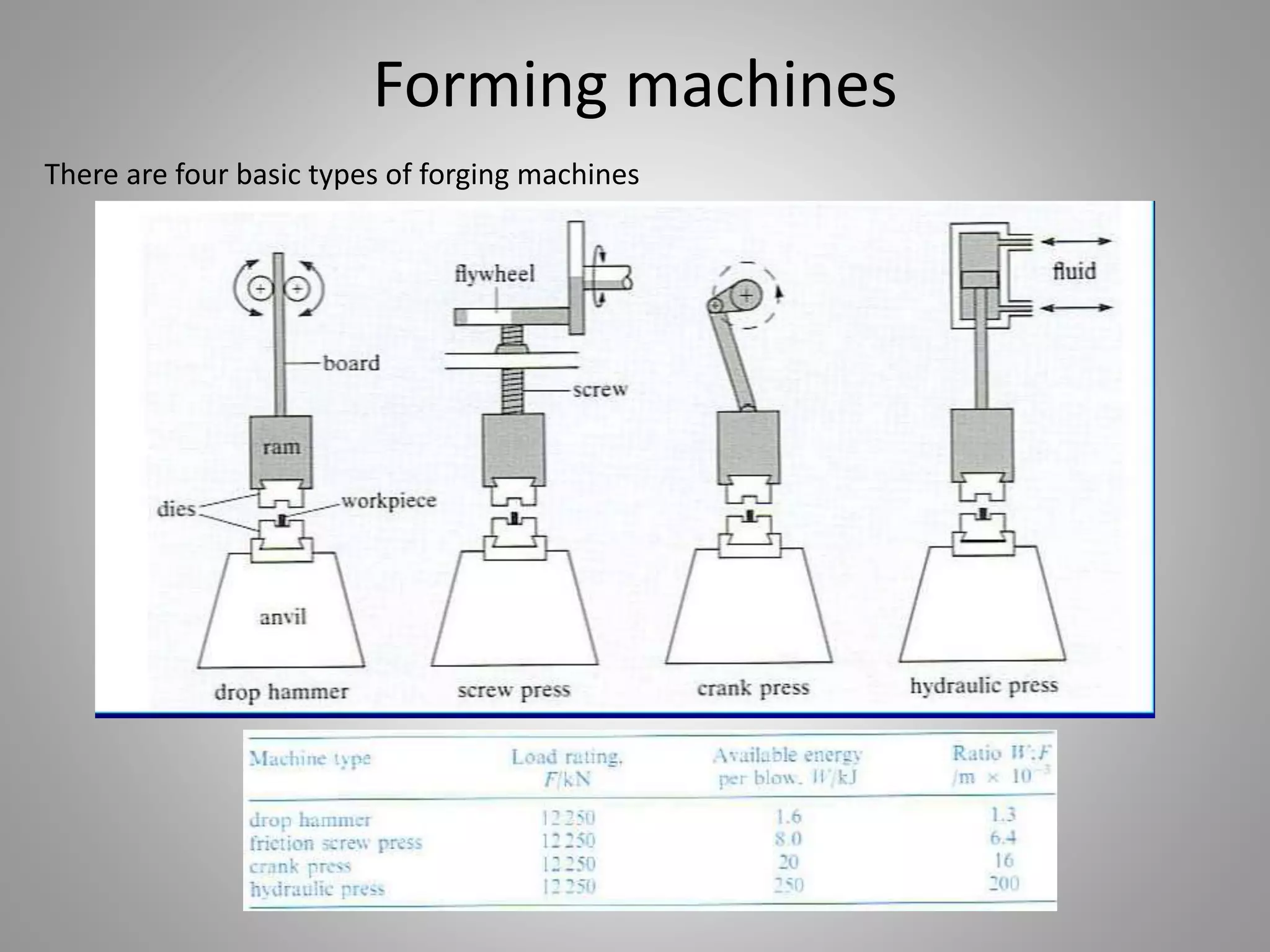
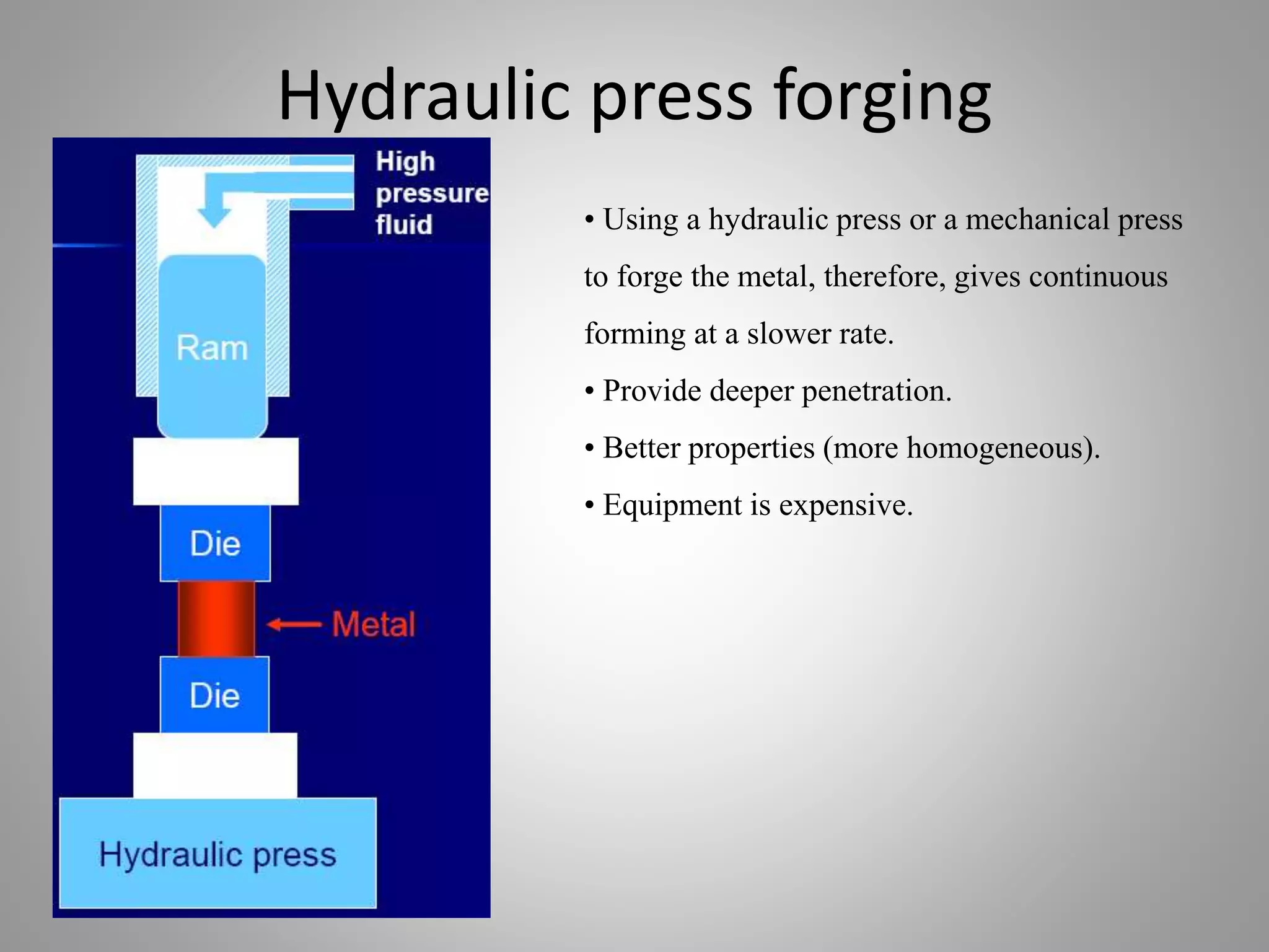
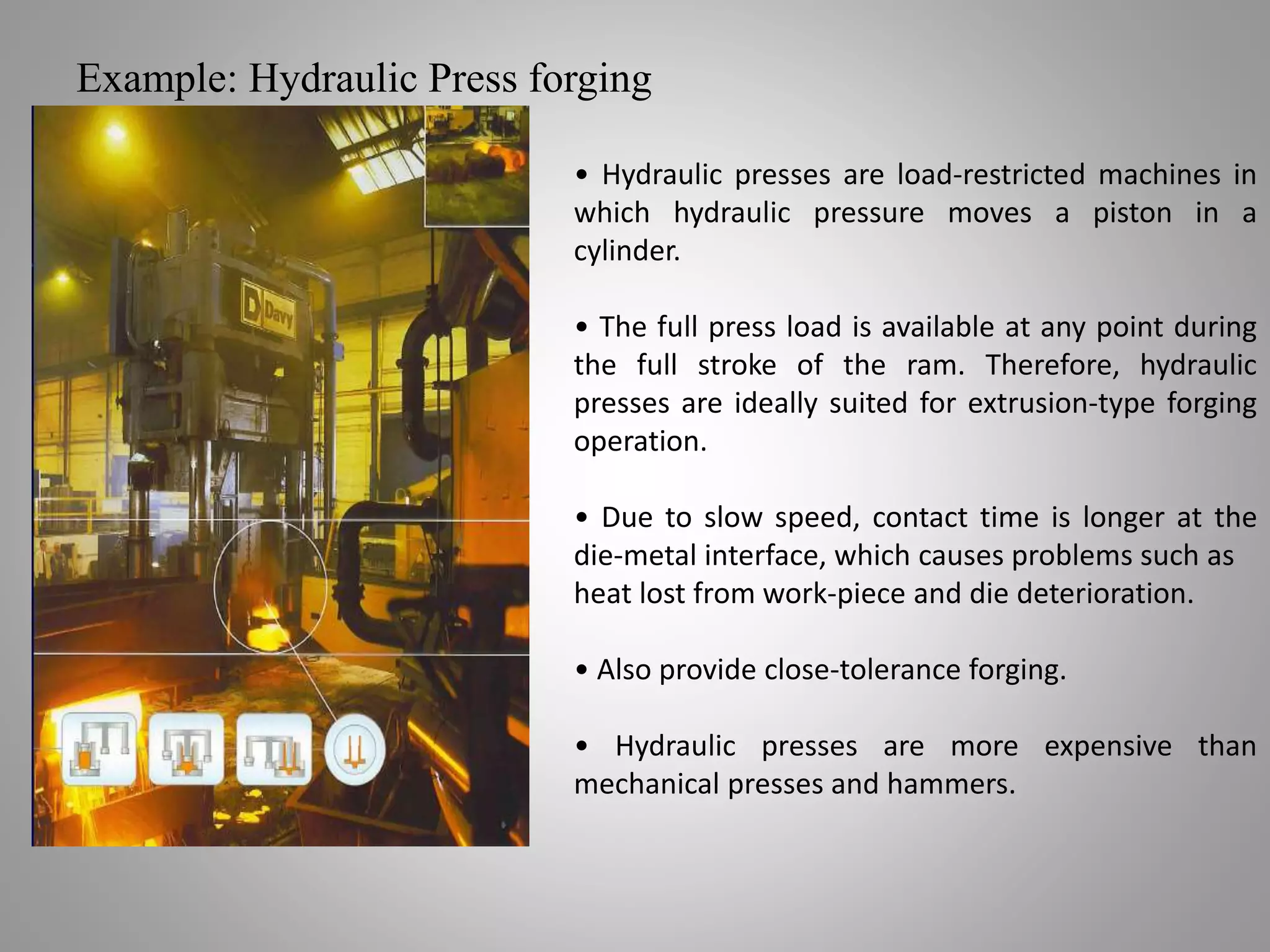
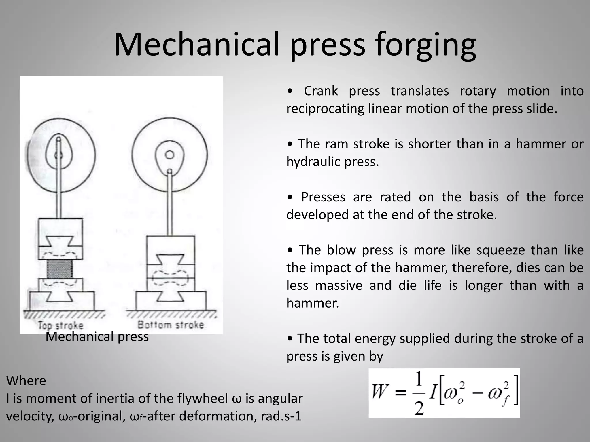
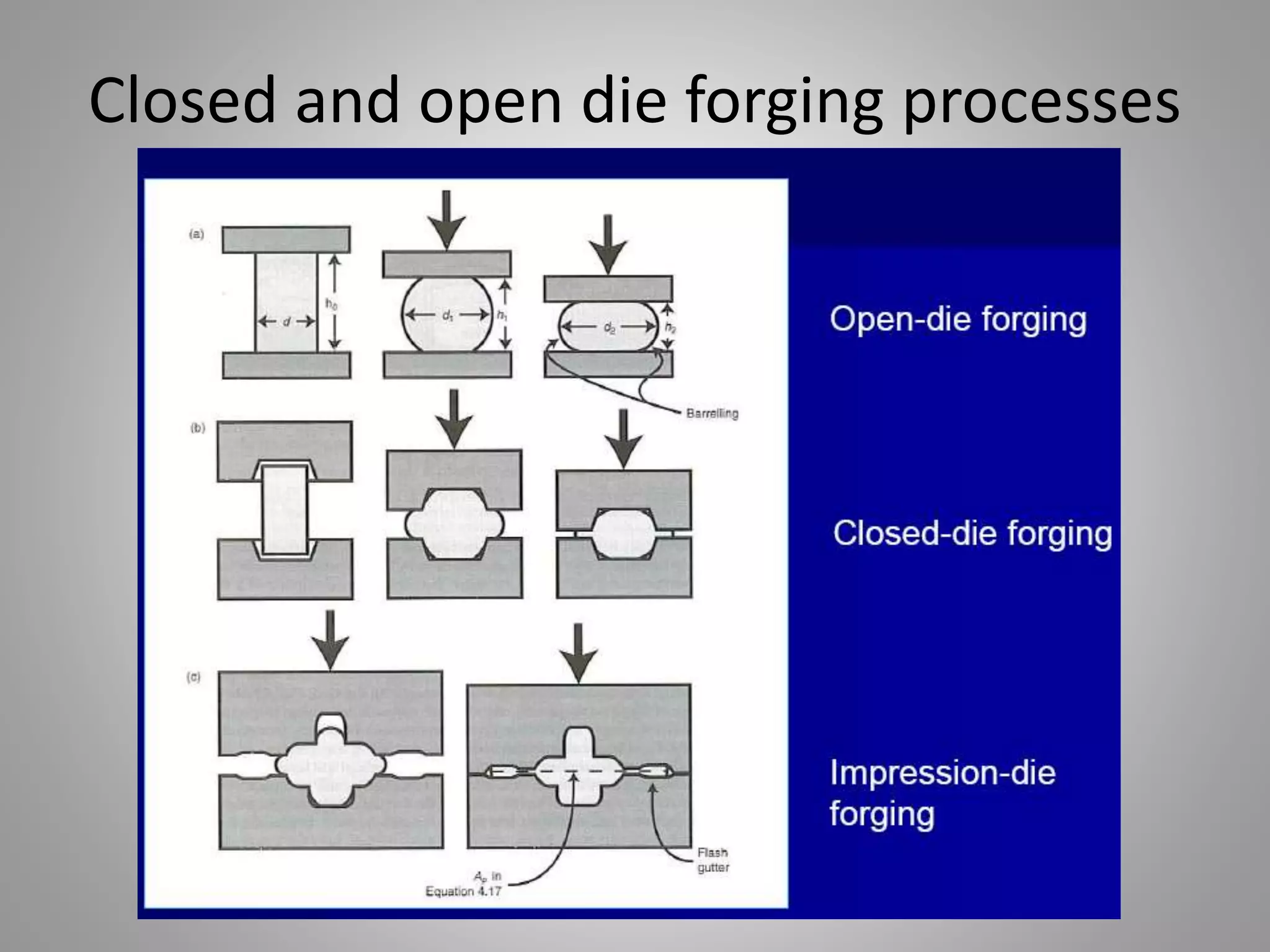
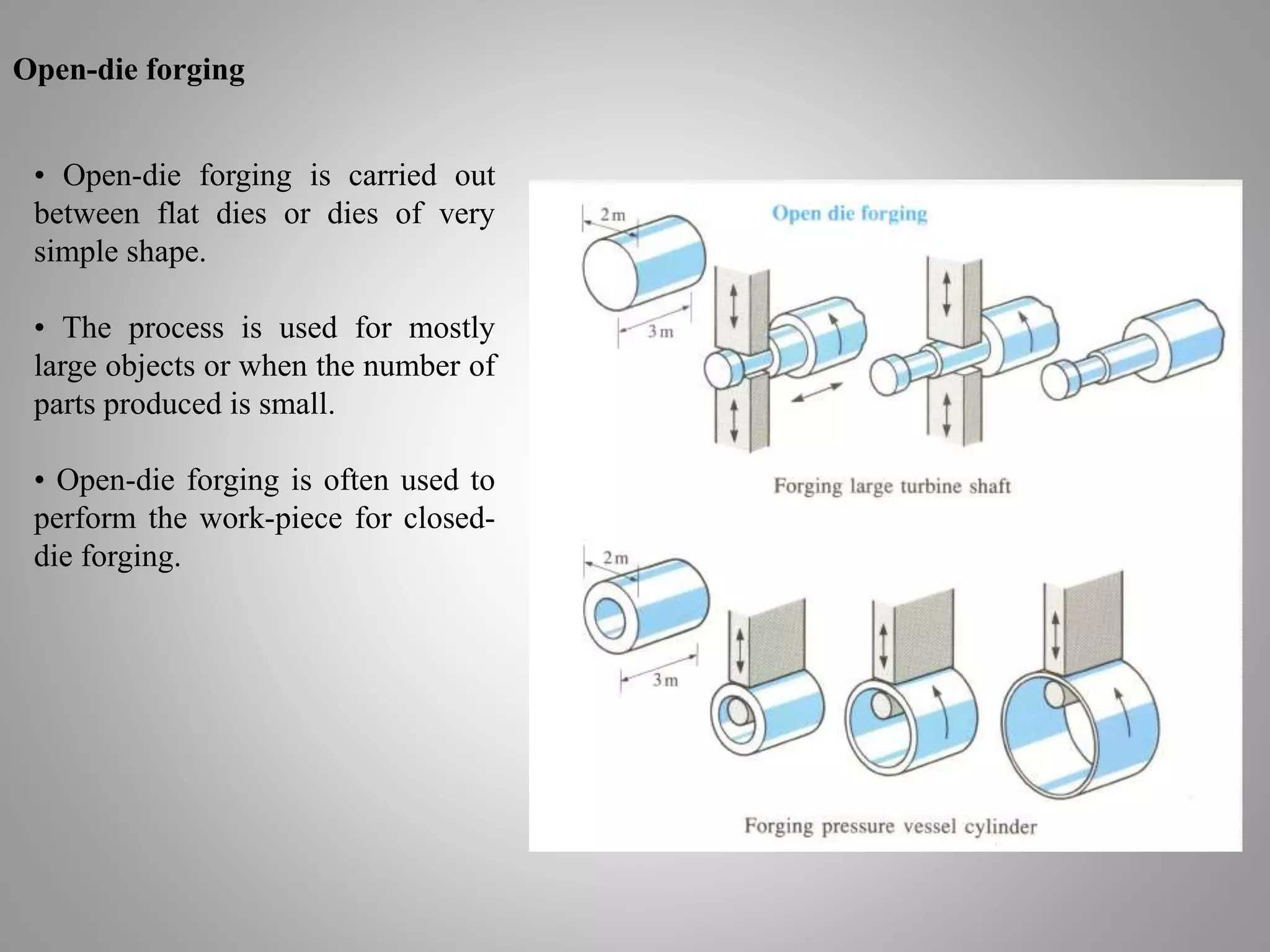
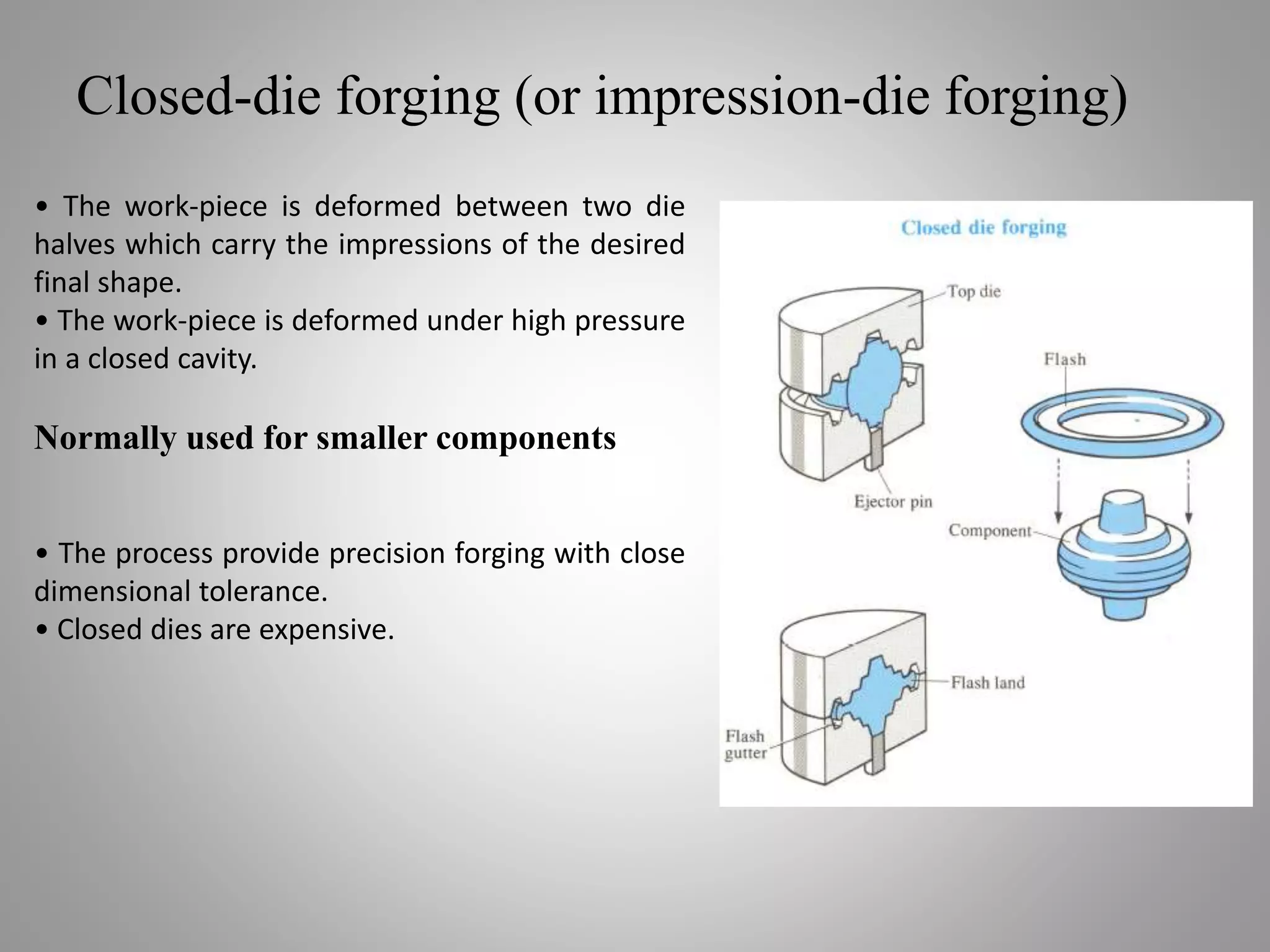
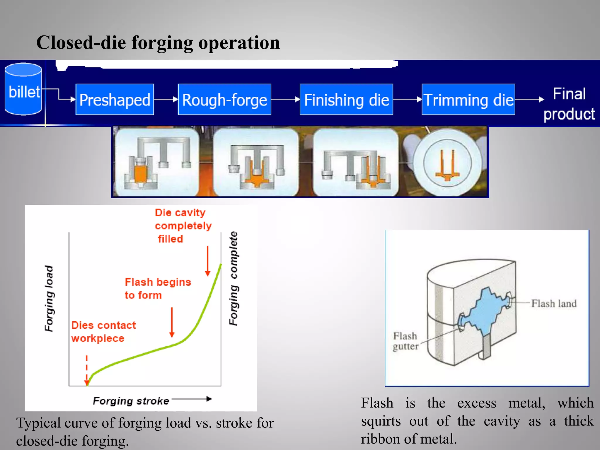
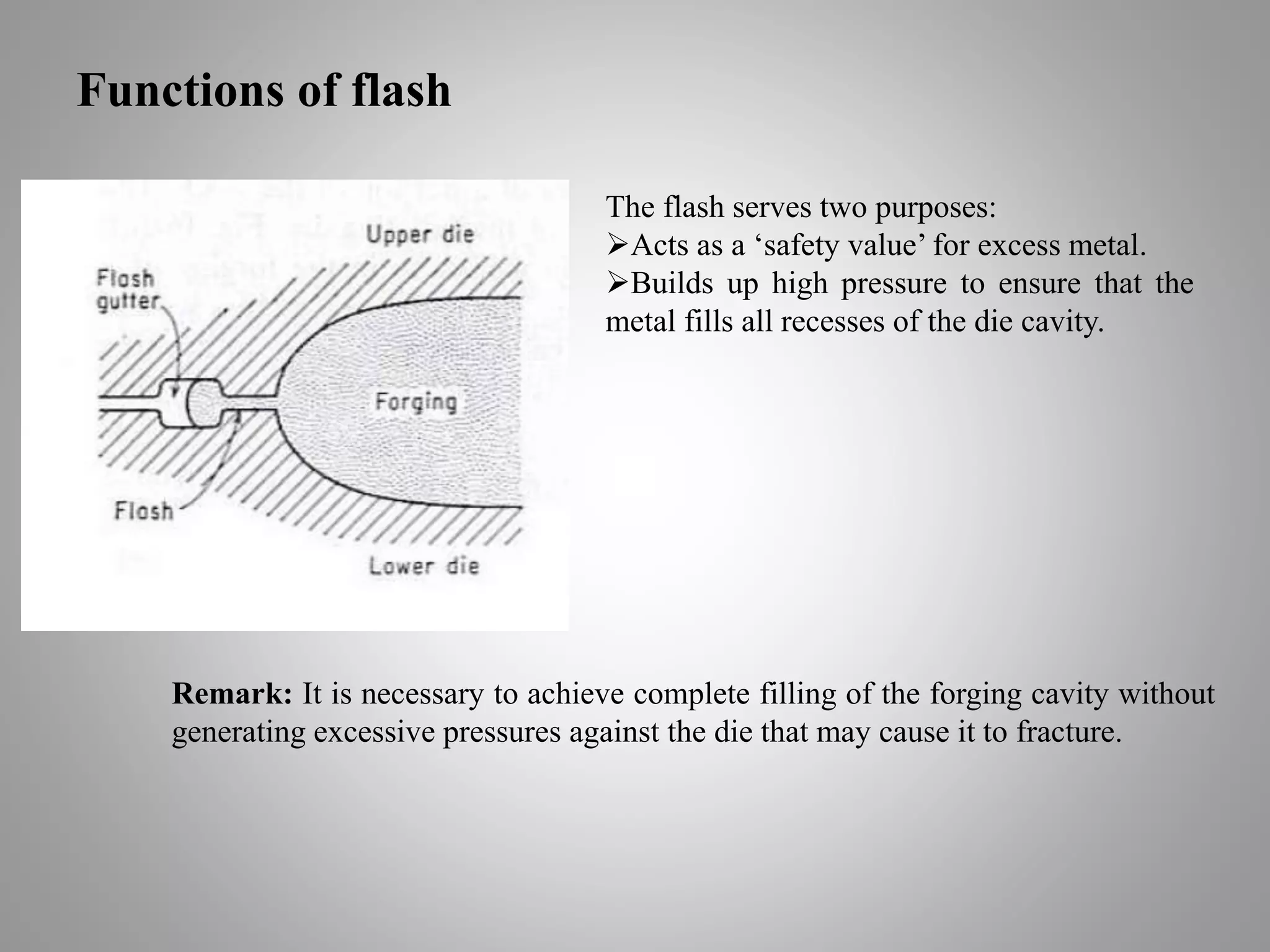
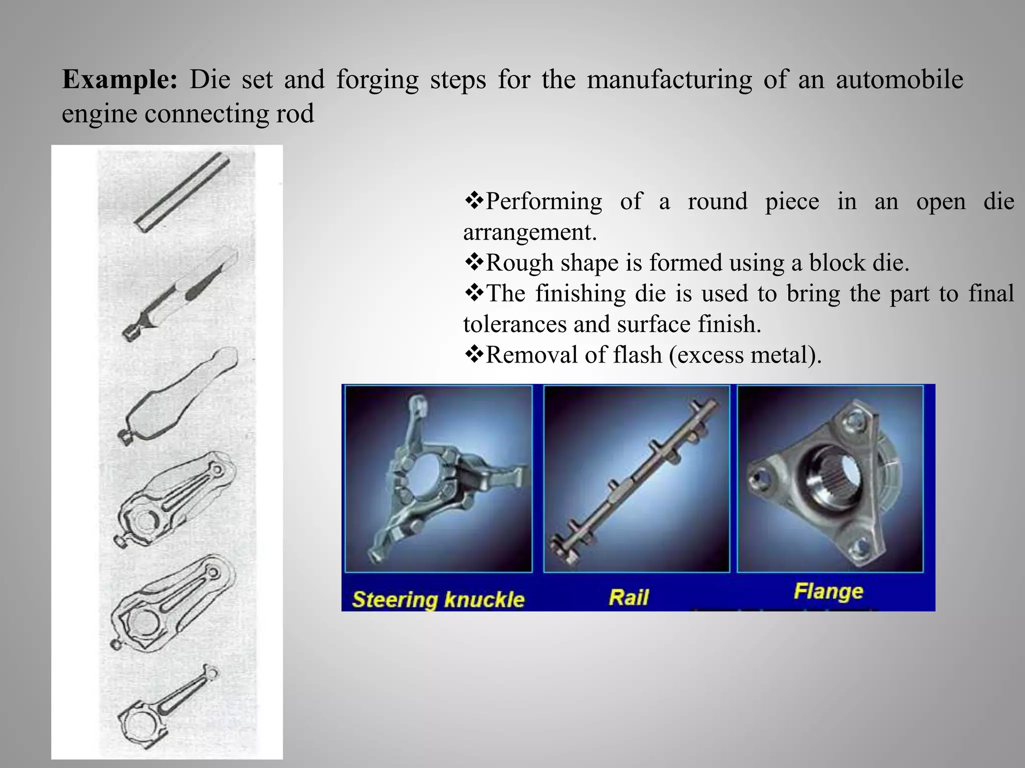
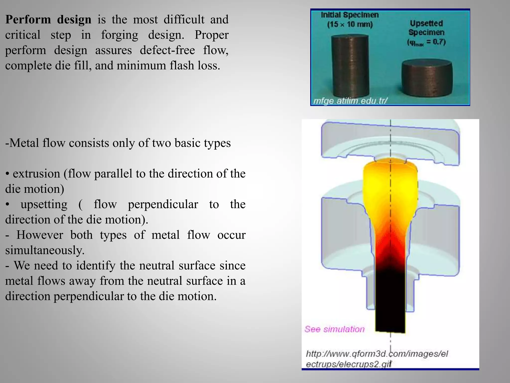
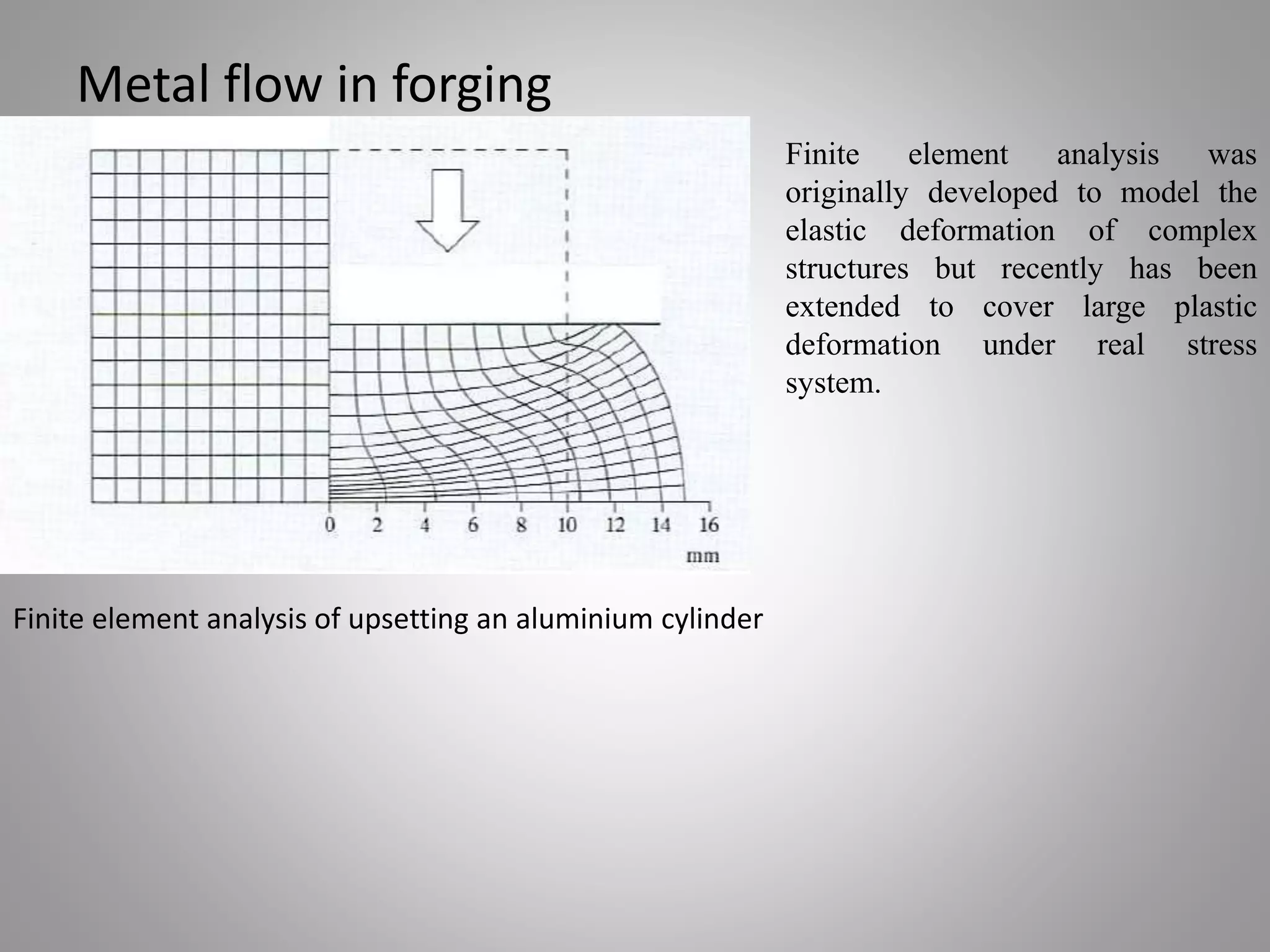
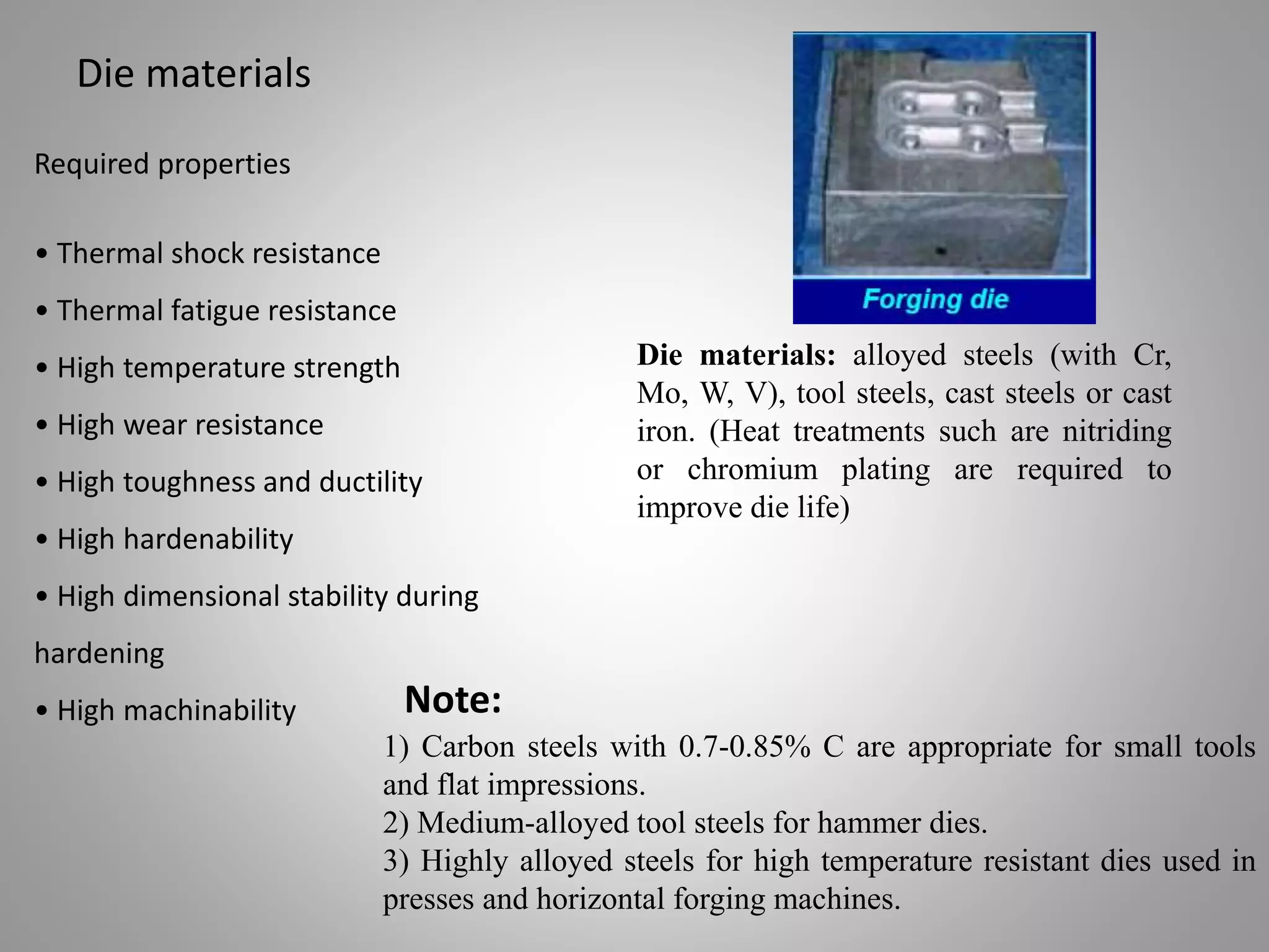
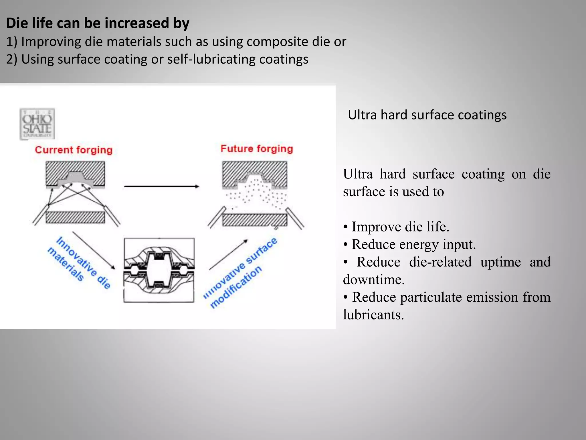
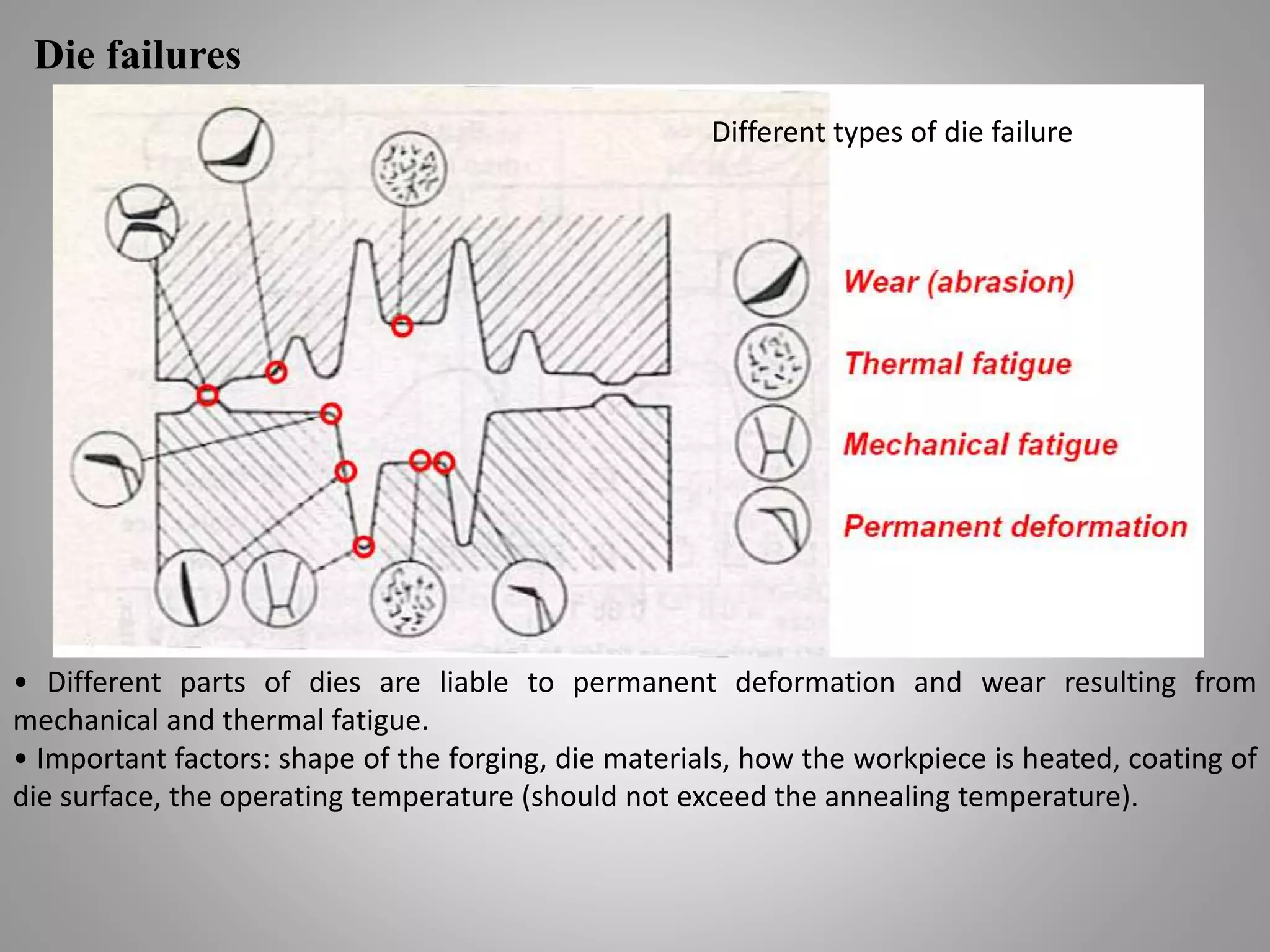
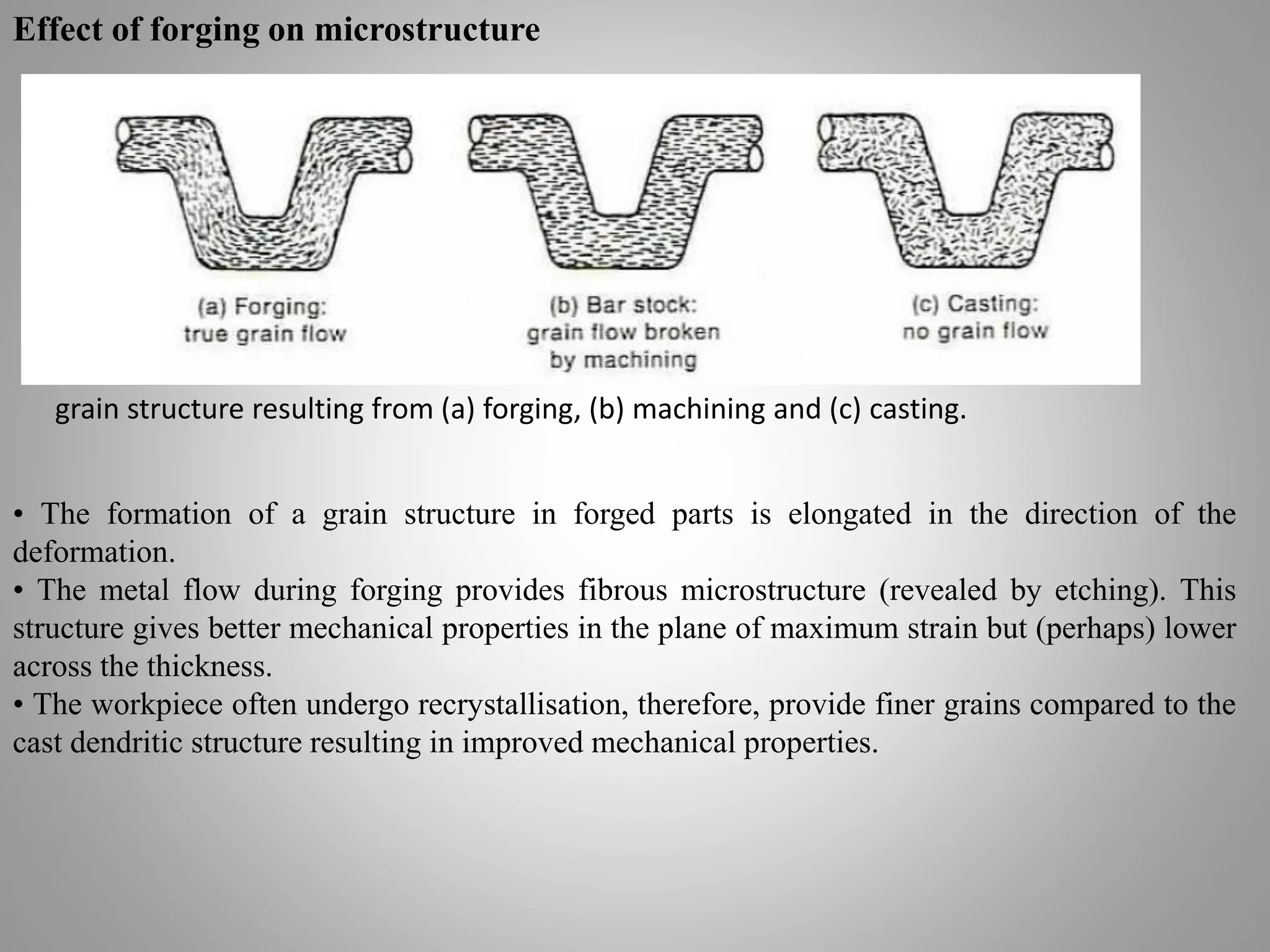
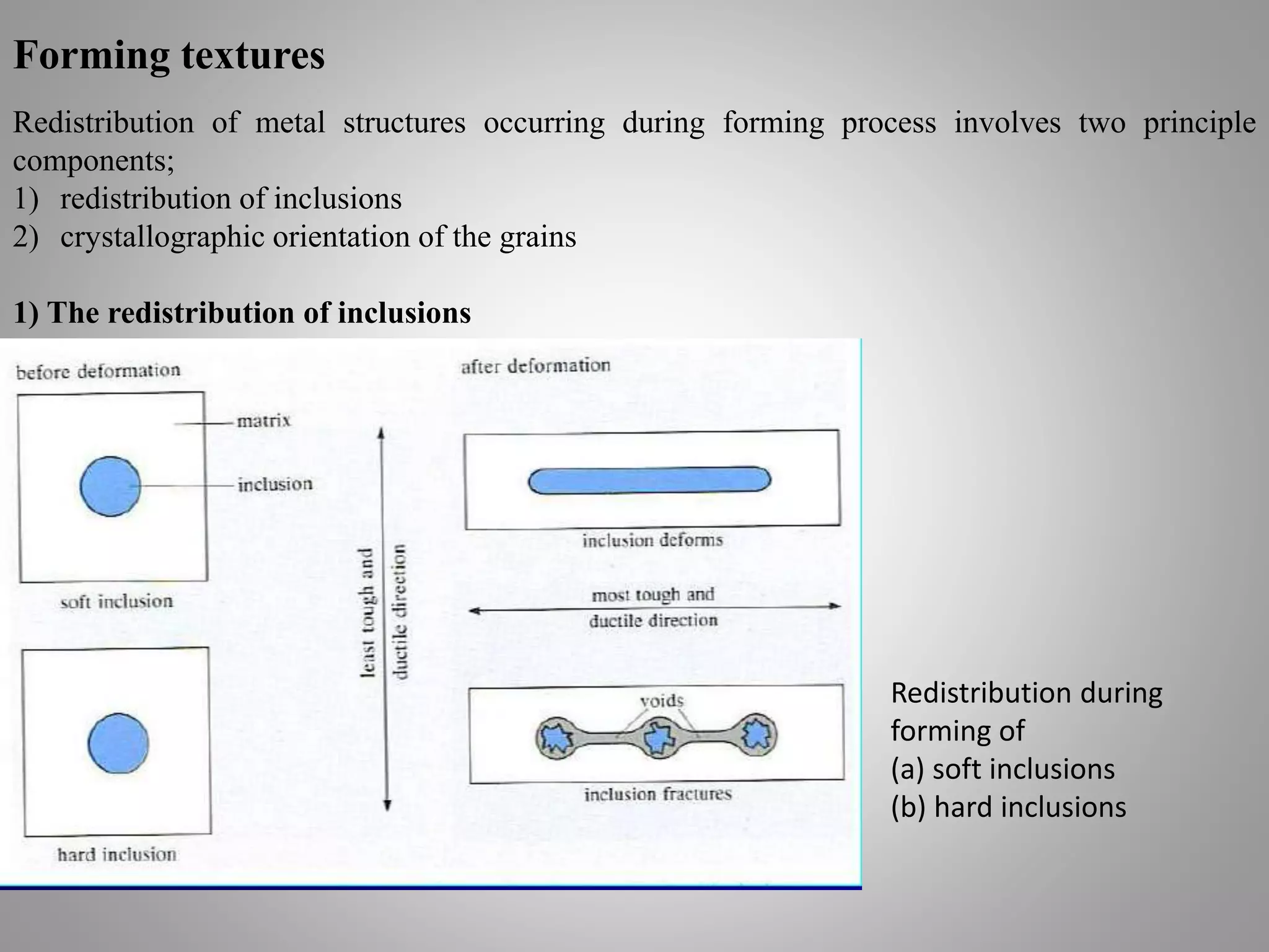
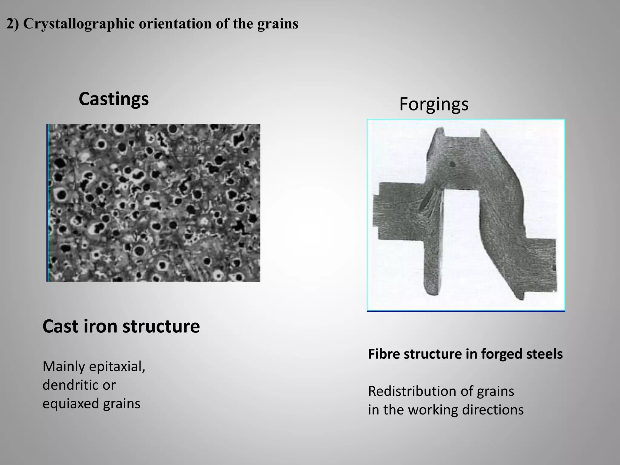
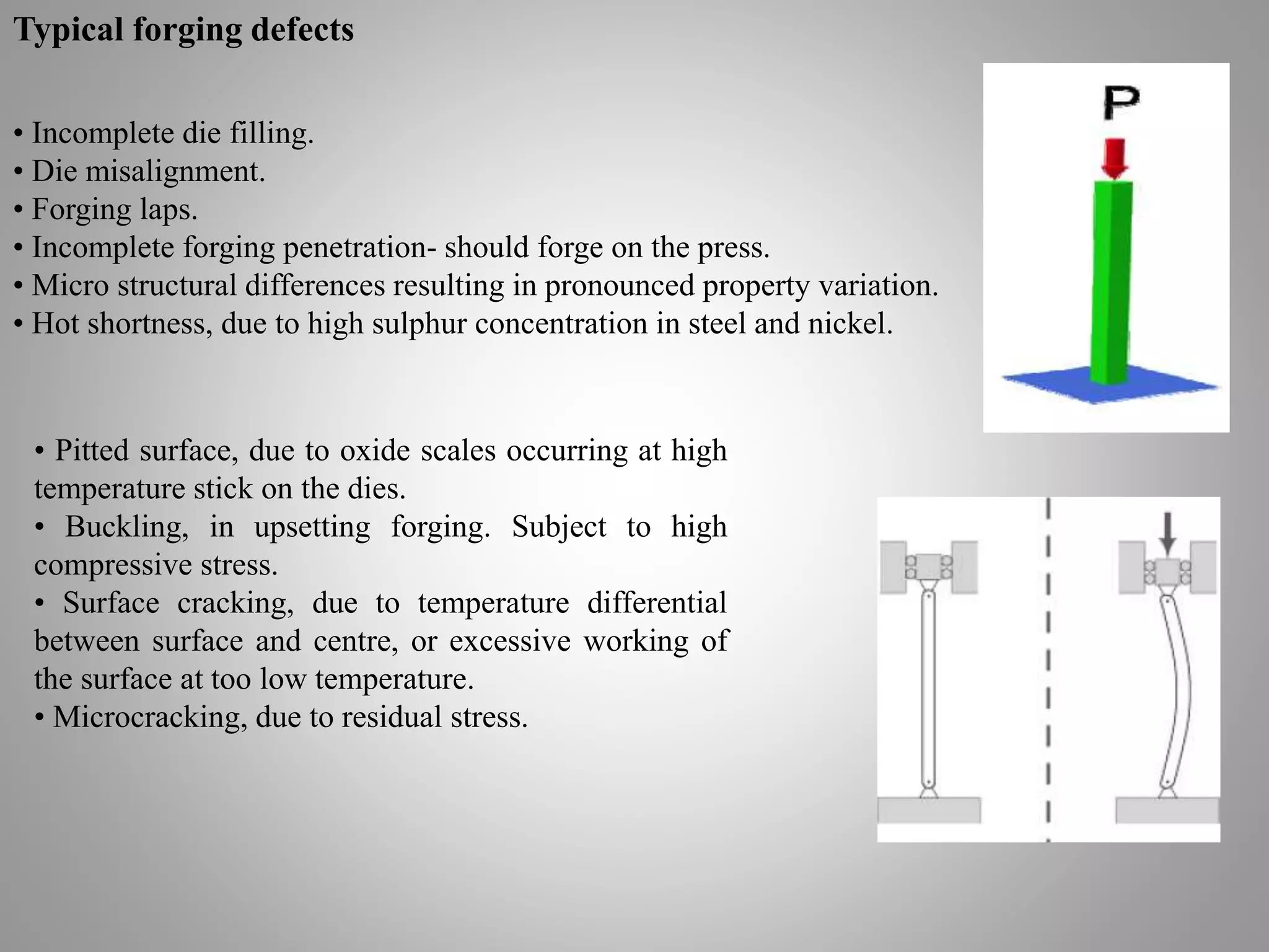
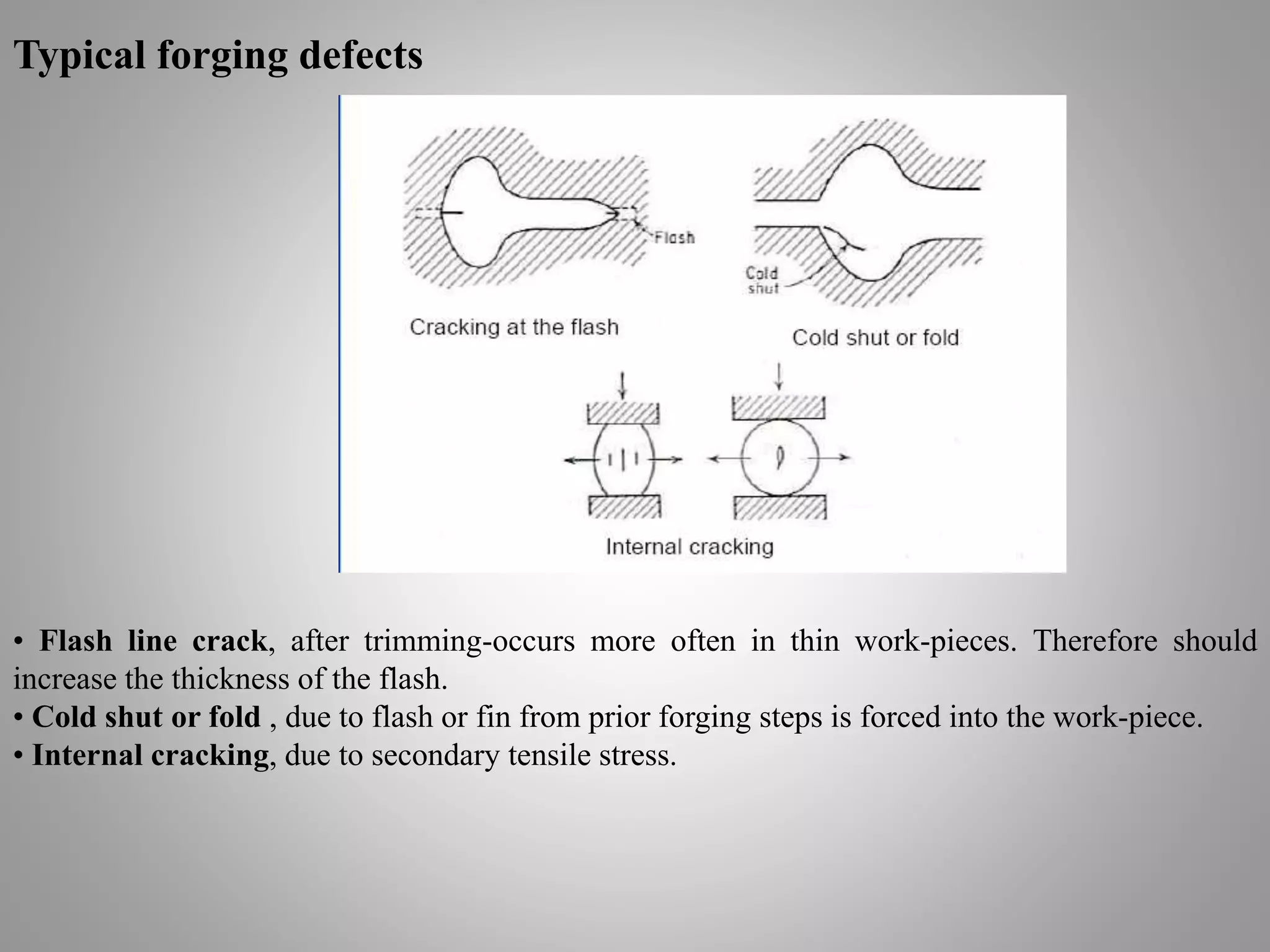
Forging Processes
Presented By :
M.Bilal Wahla
Subjects of interest
Introduction/objectives
Classification of forging processes
a) - Hammer or drop forging
b) - Press forging
c) - Open-die forging
d) - Closed-die forging
Effect of forging on microstructure
Residual stresses in forgings
Typical forging defects
Introduction
 Forging is the working of metal into a useful
shape by hammering or pressing.
 The oldest of the metalworking arts
(primitive blacksmith).
 Replacement of machinery occurred during
early the Industrial revolution.
 Forging machines are now capable of
making parts ranging in size of a bolt to a
turbine rotor.
 Most forging operations are carried out hot,
although certain metals may be cold-forged.
Forging operations
Edging is used to shape the
ends of the bars and to
gather metal. The metal
flow is confined in the
horizontal direction but it
is free to flow laterally to
fill the die.
Drawing is used to reduce the
cross-sectional area of the
work-piece with concurrent
increase in length.
Piercing and punching are
used to produce holes in
metals.
Forging operations
Fullering is used to reduce the cross-sectional area
of a portion of the stock. The metal flow is outward
and away from the centre of the fuller. i.e., forging
of connecting rod for an internal combustion
engine.
Fullers come in
different shapes
Fuller move fast and moves metal perpendicular to
the face
Forging operations
Swaging is used to produce a bar with a smaller
diameter (using concave dies).
• Swaging is a special type of forging in
which metal is formed by a succession of
rapid hammer blows
• Swaging is a special type of forging in
which metal is formed by a succession of
rapid hammer blows
Swaging at the ends, ready for next forming process
Classification of forging processes
By equipment
1) Forging hammer or drop hammer
2) Press forging
By process
1) Open - die forging
2) Closed - die forging
Forming machines
There are four basic types of forging machines
Hammer and press forging processes
Forging hammers There are two basic types of forging hammers used;
• Board hammer
• Power hammer
Forging presses There are two basic types of forging presses available;
• Mechanical presses
• Hydraulic presses
Board hammer –forging hammer
• The upper die and ram are raised by friction rolls
gripping the board.
• After releasing the board, the ram falls under
gravity to produce the blow energy.
• The hammer can strike between 60-150 blows per
minute depending on size and capacity.
• The board hammer is an energy restricted machine.
The blow energy supplied equal the potential energy
due to the weight and the height of the fall.
• This energy will be delivered to the metal work-
piece to produce plastic deformation.
Board hammer
Forging hammer or drop hammer
• Provide rapid impact blows to the surface of the
metal.
• Dies are in two halves
- Lower : fixed to anvil
- Upper : moves up and down with the TUP.
• Energy (from a gravity drop) is adsorbed onto the
metal, in which the maximum impact is on the metal
surface.
• Dies are expensive being accurately machined from
special alloys (susceptible to thermal shock).
• Drop forging is good for mass production of
complex shapes.
Example:
Forging hammer or drop hammer
The energy supplied by the blow is
equal to the potential energy due
to the weight of the ram and the
height of the fall.
Potential energy = mgh
Power hammer
• Power hammer provides greater capacity, in
which the ram is accelerated on the down
stroke by steam or air pressure in addition to
gravity.
• Steam or air pressure is also used to raise
the ram on the upstroke.
• The total energy supplied to the blow in a
power drop hammer is given by
Where
m = mass
v = velocity of ram at start of deformation
g = acceleration of gravity
p = air or steam pressure acting on ram cylinder on down
stroke
A = area of ram cylinder
H = height of the ram drop
Hydraulic press forging
• Using a hydraulic press or a mechanical press
to forge the metal, therefore, gives continuous
forming at a slower rate.
• Provide deeper penetration.
• Better properties (more homogeneous).
• Equipment is expensive.
Example: Hydraulic Press forging
• Hydraulic presses are load-restricted machines in
which hydraulic pressure moves a piston in a
cylinder.
• The full press load is available at any point during
the full stroke of the ram. Therefore, hydraulic
presses are ideally suited for extrusion-type forging
operation.
• Due to slow speed, contact time is longer at the
die-metal interface, which causes problems such as
heat lost from work-piece and die deterioration.
• Also provide close-tolerance forging.
• Hydraulic presses are more expensive than
mechanical presses and hammers.
Mechanical press forging
• Crank press translates rotary motion into
reciprocating linear motion of the press slide.
• The ram stroke is shorter than in a hammer or
hydraulic press.
• Presses are rated on the basis of the force
developed at the end of the stroke.
• The blow press is more like squeeze than like
the impact of the hammer, therefore, dies can be
less massive and die life is longer than with a
hammer.
• The total energy supplied during the stroke of a
press is given by
Mechanical press
Where
I is moment of inertia of the flywheel ω is angular
velocity, ωo-original, ωf-after deformation, rad.s-1
Closed and open die forging processes
Open-die forging
• Open-die forging is carried out
between flat dies or dies of very
simple shape.
• The process is used for mostly
large objects or when the number of
parts produced is small.
• Open-die forging is often used to
perform the work-piece for closed-
die forging.
Closed-die forging (or impression-die forging)
• The work-piece is deformed between two die
halves which carry the impressions of the desired
final shape.
• The work-piece is deformed under high pressure
in a closed cavity.
Normally used for smaller components
• The process provide precision forging with close
dimensional tolerance.
• Closed dies are expensive.
Closed-die forging operation
Flash is the excess metal, which
squirts out of the cavity as a thick
ribbon of metal.
Typical curve of forging load vs. stroke for
closed-die forging.
Functions of flash
The flash serves two purposes:
Acts as a ‘safety value’ for excess metal.
Builds up high pressure to ensure that the
metal fills all recesses of the die cavity.
Remark: It is necessary to achieve complete filling of the forging cavity without
generating excessive pressures against the die that may cause it to fracture.
Example: Die set and forging steps for the manufacturing of an automobile
engine connecting rod
Performing of a round piece in an open die
arrangement.
Rough shape is formed using a block die.
The finishing die is used to bring the part to final
tolerances and surface finish.
Removal of flash (excess metal).
Closed-die design
Usually the deformation in closed-die forging is very complex and the design of the
intermediate steps to make a final precision part requires considerable experience and skill.
The design of a part for production by closed-die forging involves the prediction of
• work-piece volume and weight
• number of performing steps and their configuration
• flash dimensions in performing and finishing dies the load and energy requirement for
each forging operation, for example; the flow stress of the materials, the fictional
condition, the flow of the material in order to develop the optimum geometry for
the dies.
Shape classification
The degree of difficulty increases as the geometry moves down and toward the right.
Simple parts are symmetry shape, or parts with circular, square and similar contours
Shape classification
More complicated parts have pronounced longitudinal axis and are curved in several planes.
Perform design is the most difficult and
critical step in forging design. Proper
perform design assures defect-free flow,
complete die fill, and minimum flash loss.
-Metal flow consists only of two basic types
• extrusion (flow parallel to the direction of the
die motion)
• upsetting ( flow perpendicular to the
direction of the die motion).
- However both types of metal flow occur
simultaneously.
- We need to identify the neutral surface since
metal flows away from the neutral surface in a
direction perpendicular to the die motion.
Metal flow in forging
Finite element analysis of upsetting an aluminium cylinder
Finite element analysis was
originally developed to model the
elastic deformation of complex
structures but recently has been
extended to cover large plastic
deformation under real stress
system.
Die materials
Required properties
• Thermal shock resistance
• Thermal fatigue resistance
• High temperature strength
• High wear resistance
• High toughness and ductility
• High hardenability
• High dimensional stability during
hardening
• High machinability
Die materials: alloyed steels (with Cr,
Mo, W, V), tool steels, cast steels or cast
iron. (Heat treatments such are nitriding
or chromium plating are required to
improve die life)
1) Carbon steels with 0.7-0.85% C are appropriate for small tools
and flat impressions.
2) Medium-alloyed tool steels for hammer dies.
3) Highly alloyed steels for high temperature resistant dies used in
presses and horizontal forging machines.
Note:
Die life can be increased by
1) Improving die materials such as using composite die or
2) Using surface coating or self-lubricating coatings
Ultra hard surface coatings
Ultra hard surface coating on die
surface is used to
• Improve die life.
• Reduce energy input.
• Reduce die-related uptime and
downtime.
• Reduce particulate emission from
lubricants.
Die failures
• Different parts of dies are liable to permanent deformation and wear resulting from
mechanical and thermal fatigue.
• Important factors: shape of the forging, die materials, how the workpiece is heated, coating of
die surface, the operating temperature (should not exceed the annealing temperature).
Different types of die failure
Effect of forging on microstructure
grain structure resulting from (a) forging, (b) machining and (c) casting.
• The formation of a grain structure in forged parts is elongated in the direction of the
deformation.
• The metal flow during forging provides fibrous microstructure (revealed by etching). This
structure gives better mechanical properties in the plane of maximum strain but (perhaps) lower
across the thickness.
• The workpiece often undergo recrystallisation, therefore, provide finer grains compared to the
cast dendritic structure resulting in improved mechanical properties.
Forming textures
Redistribution of metal structures occurring during forming process involves two principle
components;
1) redistribution of inclusions
2) crystallographic orientation of the grains
1) The redistribution of inclusions
Redistribution during
forming of
(a) soft inclusions
(b) hard inclusions
2) Crystallographic orientation of the grains
Castings Forgings
Fibre structure in forged steels
Redistribution of grains
in the working directions
Cast iron structure
Mainly epitaxial,
dendritic or
equiaxed grains
Residual stresses in forging
• The residual stress produced in forgings as a results of inhomogeneous deformation are
generally small because the deformation is normally carried out well into the hot-working region.
• However, appreciable residual stresses and warping can occur on the quenching of steel
forgings in heat treatment.
• Large forgings are subjected to the formation of small cracks, or flakes at the centre of the cross
section. This is associated with the high hydrogen content usually present in steel ingots of large
size, coupled with the presence of residual stresses.
• Large forgings therefore have to be slowly cooled from the working temperature.
Examples: burying the forging in ashes for a period of time or using a controlled cooling furnace.
• Finite element analysis is used to predict residual stresses in forgings.
Typical forging defects
• Incomplete die filling.
• Die misalignment.
• Forging laps.
• Incomplete forging penetration- should forge on the press.
• Micro structural differences resulting in pronounced property variation.
• Hot shortness, due to high sulphur concentration in steel and nickel.
• Pitted surface, due to oxide scales occurring at high
temperature stick on the dies.
• Buckling, in upsetting forging. Subject to high
compressive stress.
• Surface cracking, due to temperature differential
between surface and centre, or excessive working of
the surface at too low temperature.
• Microcracking, due to residual stress.
Typical forging defects
• Flash line crack, after trimming-occurs more often in thin work-pieces. Therefore should
increase the thickness of the flash.
• Cold shut or fold , due to flash or fin from prior forging steps is forced into the work-piece.
• Internal cracking, due to secondary tensile stress.
Summary
Forging

Forging

  • 1.
  • 2.
    Subjects of interest Introduction/objectives Classificationof forging processes a) - Hammer or drop forging b) - Press forging c) - Open-die forging d) - Closed-die forging Effect of forging on microstructure Residual stresses in forgings Typical forging defects
  • 3.
    Introduction  Forging isthe working of metal into a useful shape by hammering or pressing.  The oldest of the metalworking arts (primitive blacksmith).  Replacement of machinery occurred during early the Industrial revolution.  Forging machines are now capable of making parts ranging in size of a bolt to a turbine rotor.  Most forging operations are carried out hot, although certain metals may be cold-forged.
  • 4.
    Forging operations Edging isused to shape the ends of the bars and to gather metal. The metal flow is confined in the horizontal direction but it is free to flow laterally to fill the die. Drawing is used to reduce the cross-sectional area of the work-piece with concurrent increase in length. Piercing and punching are used to produce holes in metals.
  • 5.
    Forging operations Fullering isused to reduce the cross-sectional area of a portion of the stock. The metal flow is outward and away from the centre of the fuller. i.e., forging of connecting rod for an internal combustion engine. Fullers come in different shapes Fuller move fast and moves metal perpendicular to the face
  • 6.
    Forging operations Swaging isused to produce a bar with a smaller diameter (using concave dies). • Swaging is a special type of forging in which metal is formed by a succession of rapid hammer blows • Swaging is a special type of forging in which metal is formed by a succession of rapid hammer blows Swaging at the ends, ready for next forming process
  • 7.
    Classification of forgingprocesses By equipment 1) Forging hammer or drop hammer 2) Press forging By process 1) Open - die forging 2) Closed - die forging
  • 8.
    Forming machines There arefour basic types of forging machines
  • 9.
    Hammer and pressforging processes Forging hammers There are two basic types of forging hammers used; • Board hammer • Power hammer Forging presses There are two basic types of forging presses available; • Mechanical presses • Hydraulic presses
  • 10.
    Board hammer –forginghammer • The upper die and ram are raised by friction rolls gripping the board. • After releasing the board, the ram falls under gravity to produce the blow energy. • The hammer can strike between 60-150 blows per minute depending on size and capacity. • The board hammer is an energy restricted machine. The blow energy supplied equal the potential energy due to the weight and the height of the fall. • This energy will be delivered to the metal work- piece to produce plastic deformation. Board hammer
  • 11.
    Forging hammer ordrop hammer • Provide rapid impact blows to the surface of the metal. • Dies are in two halves - Lower : fixed to anvil - Upper : moves up and down with the TUP. • Energy (from a gravity drop) is adsorbed onto the metal, in which the maximum impact is on the metal surface. • Dies are expensive being accurately machined from special alloys (susceptible to thermal shock). • Drop forging is good for mass production of complex shapes.
  • 12.
    Example: Forging hammer ordrop hammer The energy supplied by the blow is equal to the potential energy due to the weight of the ram and the height of the fall. Potential energy = mgh
  • 13.
    Power hammer • Powerhammer provides greater capacity, in which the ram is accelerated on the down stroke by steam or air pressure in addition to gravity. • Steam or air pressure is also used to raise the ram on the upstroke. • The total energy supplied to the blow in a power drop hammer is given by Where m = mass v = velocity of ram at start of deformation g = acceleration of gravity p = air or steam pressure acting on ram cylinder on down stroke A = area of ram cylinder H = height of the ram drop
  • 14.
    Hydraulic press forging •Using a hydraulic press or a mechanical press to forge the metal, therefore, gives continuous forming at a slower rate. • Provide deeper penetration. • Better properties (more homogeneous). • Equipment is expensive.
  • 15.
    Example: Hydraulic Pressforging • Hydraulic presses are load-restricted machines in which hydraulic pressure moves a piston in a cylinder. • The full press load is available at any point during the full stroke of the ram. Therefore, hydraulic presses are ideally suited for extrusion-type forging operation. • Due to slow speed, contact time is longer at the die-metal interface, which causes problems such as heat lost from work-piece and die deterioration. • Also provide close-tolerance forging. • Hydraulic presses are more expensive than mechanical presses and hammers.
  • 16.
    Mechanical press forging •Crank press translates rotary motion into reciprocating linear motion of the press slide. • The ram stroke is shorter than in a hammer or hydraulic press. • Presses are rated on the basis of the force developed at the end of the stroke. • The blow press is more like squeeze than like the impact of the hammer, therefore, dies can be less massive and die life is longer than with a hammer. • The total energy supplied during the stroke of a press is given by Mechanical press Where I is moment of inertia of the flywheel ω is angular velocity, ωo-original, ωf-after deformation, rad.s-1
  • 17.
    Closed and opendie forging processes
  • 18.
    Open-die forging • Open-dieforging is carried out between flat dies or dies of very simple shape. • The process is used for mostly large objects or when the number of parts produced is small. • Open-die forging is often used to perform the work-piece for closed- die forging.
  • 19.
    Closed-die forging (orimpression-die forging) • The work-piece is deformed between two die halves which carry the impressions of the desired final shape. • The work-piece is deformed under high pressure in a closed cavity. Normally used for smaller components • The process provide precision forging with close dimensional tolerance. • Closed dies are expensive.
  • 20.
    Closed-die forging operation Flashis the excess metal, which squirts out of the cavity as a thick ribbon of metal. Typical curve of forging load vs. stroke for closed-die forging.
  • 21.
    Functions of flash Theflash serves two purposes: Acts as a ‘safety value’ for excess metal. Builds up high pressure to ensure that the metal fills all recesses of the die cavity. Remark: It is necessary to achieve complete filling of the forging cavity without generating excessive pressures against the die that may cause it to fracture.
  • 22.
    Example: Die setand forging steps for the manufacturing of an automobile engine connecting rod Performing of a round piece in an open die arrangement. Rough shape is formed using a block die. The finishing die is used to bring the part to final tolerances and surface finish. Removal of flash (excess metal).
  • 23.
    Closed-die design Usually thedeformation in closed-die forging is very complex and the design of the intermediate steps to make a final precision part requires considerable experience and skill. The design of a part for production by closed-die forging involves the prediction of • work-piece volume and weight • number of performing steps and their configuration • flash dimensions in performing and finishing dies the load and energy requirement for each forging operation, for example; the flow stress of the materials, the fictional condition, the flow of the material in order to develop the optimum geometry for the dies.
  • 24.
    Shape classification The degreeof difficulty increases as the geometry moves down and toward the right. Simple parts are symmetry shape, or parts with circular, square and similar contours
  • 25.
    Shape classification More complicatedparts have pronounced longitudinal axis and are curved in several planes.
  • 26.
    Perform design isthe most difficult and critical step in forging design. Proper perform design assures defect-free flow, complete die fill, and minimum flash loss. -Metal flow consists only of two basic types • extrusion (flow parallel to the direction of the die motion) • upsetting ( flow perpendicular to the direction of the die motion). - However both types of metal flow occur simultaneously. - We need to identify the neutral surface since metal flows away from the neutral surface in a direction perpendicular to the die motion.
  • 27.
    Metal flow inforging Finite element analysis of upsetting an aluminium cylinder Finite element analysis was originally developed to model the elastic deformation of complex structures but recently has been extended to cover large plastic deformation under real stress system.
  • 28.
    Die materials Required properties •Thermal shock resistance • Thermal fatigue resistance • High temperature strength • High wear resistance • High toughness and ductility • High hardenability • High dimensional stability during hardening • High machinability Die materials: alloyed steels (with Cr, Mo, W, V), tool steels, cast steels or cast iron. (Heat treatments such are nitriding or chromium plating are required to improve die life) 1) Carbon steels with 0.7-0.85% C are appropriate for small tools and flat impressions. 2) Medium-alloyed tool steels for hammer dies. 3) Highly alloyed steels for high temperature resistant dies used in presses and horizontal forging machines. Note:
  • 29.
    Die life canbe increased by 1) Improving die materials such as using composite die or 2) Using surface coating or self-lubricating coatings Ultra hard surface coatings Ultra hard surface coating on die surface is used to • Improve die life. • Reduce energy input. • Reduce die-related uptime and downtime. • Reduce particulate emission from lubricants.
  • 30.
    Die failures • Differentparts of dies are liable to permanent deformation and wear resulting from mechanical and thermal fatigue. • Important factors: shape of the forging, die materials, how the workpiece is heated, coating of die surface, the operating temperature (should not exceed the annealing temperature). Different types of die failure
  • 31.
    Effect of forgingon microstructure grain structure resulting from (a) forging, (b) machining and (c) casting. • The formation of a grain structure in forged parts is elongated in the direction of the deformation. • The metal flow during forging provides fibrous microstructure (revealed by etching). This structure gives better mechanical properties in the plane of maximum strain but (perhaps) lower across the thickness. • The workpiece often undergo recrystallisation, therefore, provide finer grains compared to the cast dendritic structure resulting in improved mechanical properties.
  • 32.
    Forming textures Redistribution ofmetal structures occurring during forming process involves two principle components; 1) redistribution of inclusions 2) crystallographic orientation of the grains 1) The redistribution of inclusions Redistribution during forming of (a) soft inclusions (b) hard inclusions
  • 33.
    2) Crystallographic orientationof the grains Castings Forgings Fibre structure in forged steels Redistribution of grains in the working directions Cast iron structure Mainly epitaxial, dendritic or equiaxed grains
  • 34.
    Residual stresses inforging • The residual stress produced in forgings as a results of inhomogeneous deformation are generally small because the deformation is normally carried out well into the hot-working region. • However, appreciable residual stresses and warping can occur on the quenching of steel forgings in heat treatment. • Large forgings are subjected to the formation of small cracks, or flakes at the centre of the cross section. This is associated with the high hydrogen content usually present in steel ingots of large size, coupled with the presence of residual stresses. • Large forgings therefore have to be slowly cooled from the working temperature. Examples: burying the forging in ashes for a period of time or using a controlled cooling furnace. • Finite element analysis is used to predict residual stresses in forgings.
  • 35.
    Typical forging defects •Incomplete die filling. • Die misalignment. • Forging laps. • Incomplete forging penetration- should forge on the press. • Micro structural differences resulting in pronounced property variation. • Hot shortness, due to high sulphur concentration in steel and nickel. • Pitted surface, due to oxide scales occurring at high temperature stick on the dies. • Buckling, in upsetting forging. Subject to high compressive stress. • Surface cracking, due to temperature differential between surface and centre, or excessive working of the surface at too low temperature. • Microcracking, due to residual stress.
  • 36.
    Typical forging defects •Flash line crack, after trimming-occurs more often in thin work-pieces. Therefore should increase the thickness of the flash. • Cold shut or fold , due to flash or fin from prior forging steps is forced into the work-piece. • Internal cracking, due to secondary tensile stress.
  • 37.