HISTORY
∞ The latheis an ancient tool.
∞ The earliest evidence of a
lathe dates back to Anc
ient Egypt around 1300 BC.
∞ There is also tenuous
evidence for its existence
at a Mycenaean Greek site,
dating back as far as the
13th or 14th century BC.
3.
INTRODUCTION
3
∞The lathe machinewas also utilised in Ancient
Greece, as we’d now call the two-person model.
∞One workman would turn a wooden workpiece with
rope in the lathe frame, and another would shape the
material with a sharp tool.
∞ The lathe is a simple device that rotates a piece of
metal, wood, or stone to create a uniformly curved
edge.
∞ In addition to cutting and grinding, the lathe can be
used in sanding, facing, and knurling.
∞ While we use a mechanical lathe today, people used
simplified versions of the lathe as far back as ancient
Egypt.
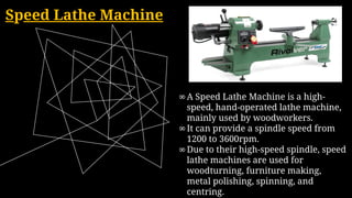
Speed Lathe Machine
∞ASpeed Lathe Machine is a high-
speed, hand-operated lathe machine,
mainly used by woodworkers.
∞It can provide a spindle speed from
1200 to 3600rpm.
∞Due to their high-speed spindle, speed
lathe machines are used for
woodturning, furniture making,
metal polishing, spinning, and
centring.
8.
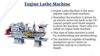
Engine Lathe Machine
8
∞Engine Lathe Machine is the most
popular type of lathe machine.
∞ Nowadays the machine is driven by
an electric motor but back in the 19th
century people used steam engines
to drive the machine. That’s why it is
called an engine lathe machine.
∞ This type of lathe machine is used
for woodworking and metalworking.
∞ The machine is capable of handling
workpieces up to 1 meter in
diameter, and up to 4 meters in
length.
9.
Production Lathe Machine
9
∞A lathe is a machine tool that rotates
a workpiece about an axis of rotation
to perform various operations, with
tools applied to the workpiece to
create an object with symmetry
about that axis.
∞ A lathe consists of four main parts:
the bed, spindle, turret, and tailstock.
Briefly, the main spindle holds the
material and rotates it. The turret,
where the tool is attached, moves to
shape the part to be machined. The
10.
Automatic Lathe Machine
10
∞An automatic Lathe machine has a group of
mechanisms that makes it capable of
automatically changing and feeding cutting
tools.
∞ When you have a complicated precision
operations job, that requires skills, you have to
produce it in mass quantity. This machine is
suitable.
11.
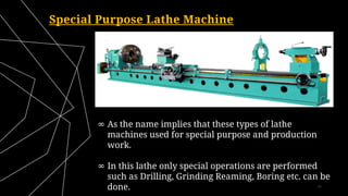
Special Purpose LatheMachine
11
∞ As the name implies that these types of lathe
machines used for special purpose and production
work.
∞ In this lathe only special operations are performed
such as Drilling, Grinding Reaming, Boring etc. can be
done.
12.
Numerical Control LatheMachine
12
∞ CNC Lathe Machines are the most up-to-date lathe
machines in terms of technology.
∞ They come with a modern computer numeric control
system (CNC). You can use this control system to add a
CAD/CAM program and after that, whenever you
command the machine, it will start and perform the
machining operation according to your program input.
13.
13
SPECIFICATION
∞Height of centrefrom the lathe bed – 125 mm
∞Distance between two centres – 500 mm
∞Largest Diameter of bar – 200mm to 1600mm
∞Length of Bed - 7' to 24'
14.
COMPONENTS & Functions
14
∞Headstock :
The headstock is found at the end of
the bed. Once clamped to the end,
the headstock provides the rotational
power for the lathe's operations.
∞ Bed :
The bed is a large horizontal
structure or beam that supports
other parts of a lathe like the
headstock and tailstock. Except
woodworking lathes, nearly all
lathes have a bed. It's the long
15.
15
∞ Tailstock :
Locatedopposite the headstock on a CNC
machine lathe, tailstocks are used to secure
and support the free end of a workpiece
while it is being machined. A tailstock
ensures that the work piece's longitudinal
rotary axis is held steady and precisely
parallel to the lathe bed.
∞ Carriage :
The carriage is the part of the lathe which
slides over the bed-ways between the
headstock and the tailstock. It provides
various movements for the cutting tool
16.
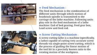
∞ Feed Mechanism:
The feed mechanism is the combination of
different units through which motion of
headstock spindle is transmitted to the
carriage of the lathe machine. Following units
play role in the feed mechanism of a lathe
machine: End of bed gearing, Feed gear box,
Lead screw and feed rod.
∞ Screw Cutting Mechanism :
A screw-cutting lathe is a machine (specifically,
a lathe) capable of cutting very accurate screw
threads via single-point screw-cutting, which is
the process of guiding the linear motion of
the tool bit in a precisely known ratio to the
rotating motion of the workpiece. 16
CLASSIFICATION OF CHUCKS
19
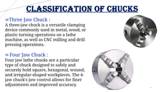
∞ThreeJaw Chuck :
A three-jaw chuck is a versatile clamping
device commonly used in metal, wood, or
plastic turning operations on a lathe
machine, as well as CNC milling and drill
pressing operations.
∞Four Jaw Chuck :
Four jaw lathe chucks are a particular
type of chuck designed to safely and
securely hold square, hexagonal, wound,
and irregular-shaped workpieces. The 4-
jaw chuck's jaw control allows for finer
adjustments and improved accuracy.
20.
20
∞ Combination Chuck:
A chuck with jaws that may be
moved simultaneously or
independently.
∞ Magnetic Chuck :
Magnetic Chucks are an
alternative to traditional
workholding machinery, as they
use magnetic force from
permanent magnets to clamp and
secure workpieces in place.
21.
21
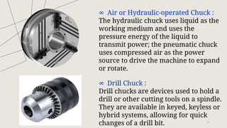
∞ Air orHydraulic-operated Chuck :
The hydraulic chuck uses liquid as the
working medium and uses the
pressure energy of the liquid to
transmit power; the pneumatic chuck
uses compressed air as the power
source to drive the machine to expand
or rotate.
∞ Drill Chuck :
Drill chucks are devices used to hold a
drill or other cutting tools on a spindle.
They are available in keyed, keyless or
hybrid systems, allowing for quick
changes of a drill bit.
22.
22
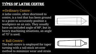
Types of LatheCentre
∞Ordinary Centre :
A lathe centre, often shortened to
centre, is a tool that has been ground
to a point to accurately position a
workpiece on an axis. They usually
have an included angle of 60°, but in
heavy machining situations, an angle
of 75° is used.
∞ Ball Centre :
The ball centre is employed for taper
turning with a tail-stock set-over
method to minimize wear and strain
23.
23
∞ Frictionless Centre:
The frictionless centre boasts the
capability to withstand high-applied
forces while allowing rotation along
with the workpiece. Its ability to
operate at very high speeds makes it
ideal for demanding machining
applications.
∞ Half Centre :
A half-centre enables one to face the
whole part when one is turning
between centres but should be
replaced when one is through with
the facing operation.
24.
24
∞ Tipped Centre:
The primary use of a center is to
ensure concentric work is
produced; this allows the
workpiece to be transferred
between machining (or
inspection) operations without
any loss of accuracy.
∞ Insert Centre :
Inserts are used as the cutting
edges for cutting tools such as
tool holders for turning and face
milling cutting for milling.
25.
Pipe Centre :
Pipecentres are a measurement
which explains what the exact
distance between your two
radiator pipes will have to be to
correctly install the home
radiator you select.
26.
26
catch plate andcarriers
∞ Catch plates and carriers play
a vital role in driving
workpieces when they are
held between two centres on a
lathe.
∞ Carriers are essentially driving
dogs that attach to the end of
the workpiece using a
setscrew, while catch plates
are bolted to the nose of the
lathe's headstock spindle.
27.
27
face plate
A faceplateis a circular metal
plate used for holding workpieces
in a lathe. When the workpiece is
clamped to the faceplate of the
lathe, turning can begin.
A workpiece may be bolted or
screwed to a faceplate, a large, flat
disk that mounts to the spindle.
28.
28
angle plate
An angleplate is a work-holding
device used as a fixture in
metalworking.
Angle plates are used to hold
workpieces square to the table
during marking-out operations.
Adjustable angle plates are also
available for workpieces that need
to be inclined, usually towards a
milling cutter.
29.
29
Types of lathemandrel
∞ Plain Mandrel :
The body of the plain mandrel is slightly
tapered to provide proper gripping of the
workpiece. It is also known as solid
mandrel. It is the type mostly commonly
used and has wide applications.
∞ Step Mandrel :
Stepped mandrels are used for collars,
washers, odd-sized jobs and so on. The
stepped mandrel will have steps of
different diameters to accommodate
different workpieces.
30.
30
∞ Collar Mandrel:
The collar mandrel is basically a
lighter plain mandrel with two
fixed collars attached at both ends.
The fixed collars fit firmly on the
workpiece. Generally, this
mandrel is used for holding
workpieces with diameters above
∞ Screwed Mandrel :
It is threaded at one end and a
collar is attached to it.
Workpieces having internal
threads are screwed on to it
against the collar for machining.
31.
31
∞ Cone Mandrel:
It consists of a solid cone attached to one
end
of the body and a sliding cone, which can
be
adjusted by turning a nut at the threaded
end.
This type is suitable for driving
workpieces
having different hole diameters.
∞ Gang Mandrel :
It has a fixed collar at one end and a
movable collar at the threaded end. This
mandrel is used to hold a set of hollow
workpieces between the two collars by
tightening the nut.
32.
32
∞ Expansion
Mandrel :
Expandingmandrels on a lathe
are a type of mandrel that grip
the interior diameter or ID of a
workpiece. On an expanding
mandrel, the shaft and sleeve
have corresponding tapers and
are machined from hardened
steel. The sleeve is slotted and
expands when pressed into the
tapered shaft.
33.
33
Different Rests ofLathe Machine
∞ Centre Rest :
The primary purpose of a lathe steady rest is to support and
stabilize long and slender workpieces while they are being turned
or machined. In most cases, you never have to replace the steady
rest and just have to replace the screws and the bearings.
34.
34
∞ Follower Rest:
The purpose of the follower rest is
to keep long or small-diameter work
from deflecting when a cutting tool
is applied to it. It is attached to the
lathe saddle and moves as the
saddle moves, keeping the point of
support directly behind the cutting
tool.
35.
35
acknowledgement
I would liketo express my special thanks of gratitude
to my teacher as well as to our principal ma'am who
gave me the golden opportunity to do this wonderful
project on the topic LATHE MACHINES, which also
helped me in doing a lot of Research and I came to
know about so many new things.....
Harshavardhan Vikramsinh
Khot
Yashwantrao Chavan Vidyalaya
10Th