Downloaded 266 times
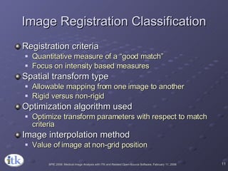
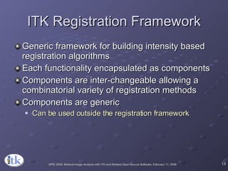
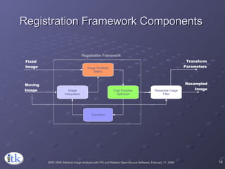
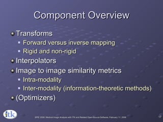
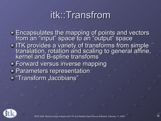

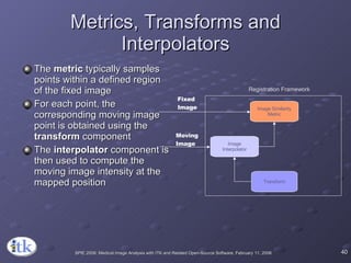
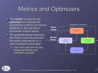
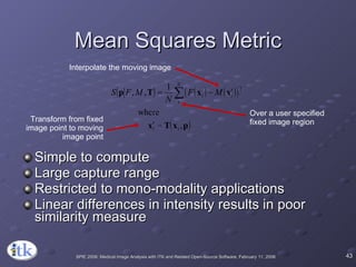


The document provides an overview of ITK registration methods, including: 1) ITK's registration framework uses a modular approach with interchangeable components like transforms, metrics, interpolators and optimizers. 2) Common registration tasks include intra-subject registration to compensate for differences in scans, and inter-subject registration to create population atlases and enable segmentation. 3) Key components include transforms to define the mapping between images, metrics to measure match quality, and interpolators to sample intensity values for non-grid positions.