Downloaded 170 times

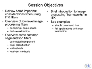
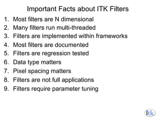
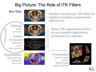
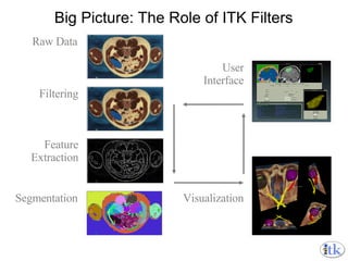
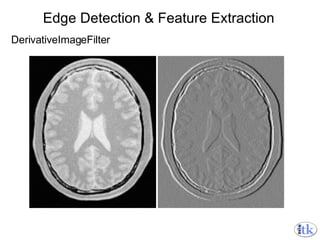
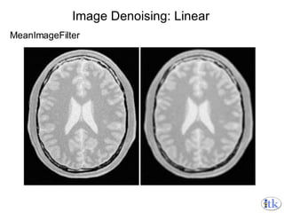
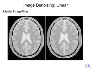
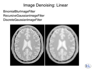
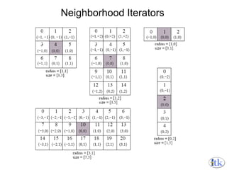
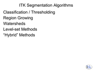
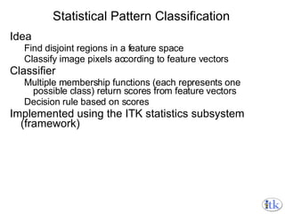
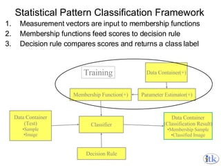
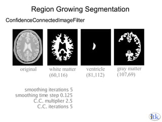
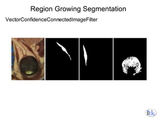
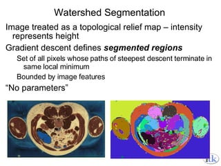
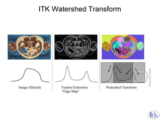
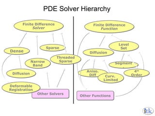
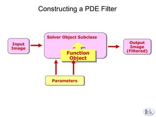
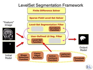
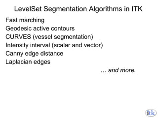
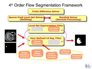
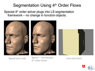
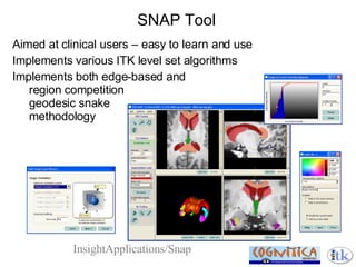
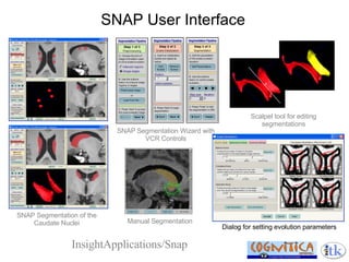


The document provides an overview of segmentation techniques in the Insight Toolkit (ITK), including: - ITK filters are components that can be combined to build segmentation applications, rather than complete applications themselves. - Common segmentation filters include region growing, watersheds, level sets, and classification/thresholding. - Advanced techniques include hybrid methods that combine filters, like region growing followed by level set refinement. - Frameworks like the image neighborhood framework and PDE solvers enable complex segmentation algorithms.