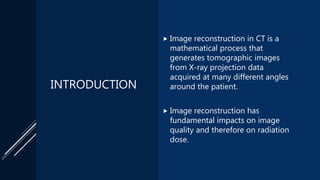
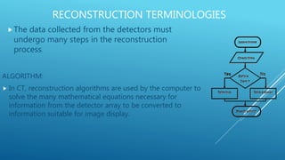
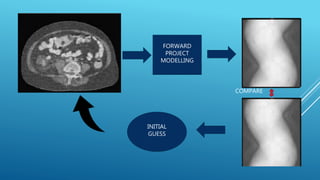
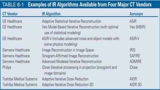
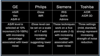
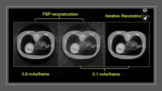
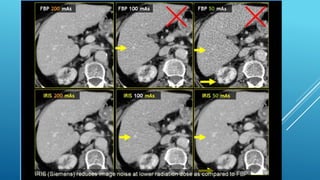
IMAGE RECONSTRUCTION
IN COMPUTED
TOMOGRAPHY
 Anjan Dangal
 B.Sc.MIT 4th Year
 National Academy of Medical Sciences, Bir Hospital
CONTENTS
 INTRODUCTION
 RECONSTRUCTION TERMINOLOGIES
 CATEGORIES OF RECONSTRUCTION
 ADVANTAGES AND DISADVANTAGES OF RECONSTRUCTION METHODS
 IR ALGORITHM FROM MAJOR VENDORS
 SUMMARY
INTRODUCTION
 Image reconstruction in CT is a
mathematical process that
generates tomographic images
from X-ray projection data
acquired at many different angles
around the patient.
 Image reconstruction has
fundamental impacts on image
quality and therefore on radiation
dose.
RECONSTRUCTION TERMINOLOGIES
The data collected from the detectors must
undergo many steps in the reconstruction
process.
ALGORITHM:
 In CT, reconstruction algorithms are used by the computer to
solve the many mathematical equations necessary for
information from the detector array to be converted to
information suitable for image display.
INTERPOLATION
 Interpolation is a mathematical method of estimating
the value of an unknown function using the known
value on either side of the function. Types:
 Linear interpolation
 Polynomial interpolation
 Spline interpolation
 Multivariate interpolation.
FOURIER
TRANSFORM Separates a function into its
frequency components.
Computers generally rely on a
version known as discrete Fourier
transform (DFT).
An efficient algorithm to compute
DFT and its inverse is called fast
Fourier transform (FFT).
Fourier inversion theorem.
CATEGORIES OF
RECONSTRUCTION
Analytical Reconstruction
Iterative Reconstruction
As the x-ray tube travels along its circular path, continuous x-ray energy is
being generated.
The path that the x-ray beam takes from the tube to the detector is referred to
as a ray.
The DAS reads each arriving ray and measures how much of the beam is
attenuated. This measurement is called a ray sum.
A complete set of ray sums is known as a view.
The system accounts for the attenuation properties of each ray sum and
correlates them with the position of the ray. The result of this type of correlation
is called an attenuation profile.
The information from all of the profiles is projected onto a matrix. This process
of converting the data from the attenuation profile to a matrix is known as back
projection.
ANALYTICAL
RECONSTRUCTION
Image reconstruction algorithm which back projects
the sinogram to 2D image Domain.
More Prone to increased noise and artifacts at low
dose.
Fast way to reconstruct CT images.
SIMPLE BACK
PROJECTION
In early 1960, simple back projection was
employed to “reconstruct” the distribution
of activity in Nuclear Medicine.
While this generated the cross sectional
images , the techniques still suffered due
to superimposed structure.
SHEEP AND LOGAN
PHANTOM
FILTERED
BACK
PROJECTION
Simple back projection produces blurred
tomographic images
If the mathematics behind the blurring is
understood , the blurring can be corrected.
This correction process is called filtering.
Once the projection data is filtered, the
filtered projection data is back projected to
form the tomographic image.
FILTER
• To minimize these artifacts, a process called filtering is applied to the scan data
before back projection occurs. The process of filtering is done through
complicated mathematic steps.
• enhanced or suppressed
• process of applying a filter function to an attenuation profile is called
convolution.
• to reconstruct an image using a different filter functions , the raw data must be availabl
for that image.
• Filtered back projection algorithms use Fourier Theory to reduce statistical
noise and create an image that is pleasing to the eye.
In a single 512 x 512 CT slice there are 262,144 unknowns to solve for.
Modern CT scanners acquire approximately 1000 projections in one rotation.
There are approximately 750 detectors in each row of a modern scanner.
Each rotation generates approximately 750, 000 equations to solve for the 262, 144
unknowns.
Because of the noise the equations are not consistent !!!!!
FBP ADVANTAGES
 Speed : 50 – 60 + images recon
per second.
 Well characterized:
 Primary recon since beginning of
CT.
 Noise properties known: linear
relationship between noise and
resolution
 Known Artifacts
FBP
DISADVANTAGES
 Simplified Assumptions:
 Limits resolutions and
predictions.
 Trouble with truncated data:
 Need to know all projections
 non uniformities
ITERATIVE IMAGE
RECONSTRUCTION(IRT)
Incorporates better mathematical CT model and iterates to
reduce inconsistencies in the image reconstruction.
Lower noise and artifacts at low dose.
Generally slower than FBP.
ADAPTIVE ITERATIVE STATISTICAL
RECONSTRUCTION
There are a large variety of algorithms used, but each starts with an
assumed image, computes projections from the image, compares it
with the original projection data, and updates the image on the basis
of the difference between the calculated and the actual projections.
These are called adaptive statistical iterative reconstruction
algorithms.
This new advanced reconstruction technique can reduce image noise,
thereby improving image quality by improving low-contrast detectability.
Compared with standard filtered back-projection methods, this
technique has been shown to reduce the radiation dose to the patient
by as much as 50%.
Most IRT results in changes in image appearance compared to
FBP.
Most IRT come in different strengths of noise reduction
potential.
Initial implementation IRT should generally start at low
strength.
IRT do not reduce dose by itself but rather allow user to reduce
dose compared to FBP.
Guess what the image slice should be ( uses FBP)
Compute the projection data.
Forward project the guess for comparison of the guess projection
data with the acquired projection data.
Calculate the ratio between the guess projection data and the
measured projection data ( this is a measure of error in guess).
Do a weighted back projection of these ratio.
Multiply the guess image by the back projected ratio (i.e.
Corrections) to get the updated image.
Begin the cycle al over again with the updated image as the new
guess.
Because of selectable factors there are many types of iterative
reconstruction algorithm.
There are many variable that must be chosen as part of an iterative
reconstruction algorithm :
How to calculate the error (correction factor)
When to stop
How to use the projections to update the update.
NEW IMAGE :
GUESS IMAGE X CORRECTION FACTOR
INITIAL
GUESS
FORWARD
PROJECT
MODELLING
COMPARE
MODELING FOR IR
 STATISTICAL MODELING:
 Focused on controlling noise
 Models only noise properties
 Takes quantum noise into action
 Does not improve resolution !!!
 PHYSICS MODELING:
 Models all aspect of scanner
 Focal spot size, geometry, beam energy, cone angle
 Extremely complex: Better the model
 Compare improve both the noise and resolution !!!
POSSIBLE ITERATIVE ADVANTAGE
Modeling:
 Allows more precise reconstructions
 Ability to better model the physics of projection
 Can help with noise and resolution
 Artifact reduction
ITERATIVE DISADVANTAGE
 Slow:
 Depending on model can be 400x slower
 Complex:
 Modeling noise is relatively fast
 Modeling physics is slow !
 Non-Linear:
 Can create plastic images
 Poorly characterized
GE
PHILIPS ITERATIVE
DOSE REDUCTION
Hybrid:
 Works in both raw data domain
and image domain.
Raw data:
 Targets noisy projection
Image data:
 Better noise model
 Multi frequency noise reduction
Majority of factory protocol are
reconstructed in 60s or less.
SIEMENS:
SAFIRE
IRIS
ADMIRE
AIDR 3D
SUMMARY
REFERENCES
• Radiation Dose Management in CT, IAEA, Online Learning Material
• CT for Technologist, Image Reconstruction.
• Computed Tomography, Physical Principles, Clinical Applications,
and Quality Control. Euclid Seeram

Image Reconstruction in Computed Tomography

  • 1.
    IMAGE RECONSTRUCTION IN COMPUTED TOMOGRAPHY Anjan Dangal  B.Sc.MIT 4th Year  National Academy of Medical Sciences, Bir Hospital
  • 2.
    CONTENTS  INTRODUCTION  RECONSTRUCTIONTERMINOLOGIES  CATEGORIES OF RECONSTRUCTION  ADVANTAGES AND DISADVANTAGES OF RECONSTRUCTION METHODS  IR ALGORITHM FROM MAJOR VENDORS  SUMMARY
  • 3.
    INTRODUCTION  Image reconstructionin CT is a mathematical process that generates tomographic images from X-ray projection data acquired at many different angles around the patient.  Image reconstruction has fundamental impacts on image quality and therefore on radiation dose.
  • 4.
    RECONSTRUCTION TERMINOLOGIES The datacollected from the detectors must undergo many steps in the reconstruction process. ALGORITHM:  In CT, reconstruction algorithms are used by the computer to solve the many mathematical equations necessary for information from the detector array to be converted to information suitable for image display.
  • 5.
    INTERPOLATION  Interpolation isa mathematical method of estimating the value of an unknown function using the known value on either side of the function. Types:  Linear interpolation  Polynomial interpolation  Spline interpolation  Multivariate interpolation.
  • 6.
    FOURIER TRANSFORM Separates afunction into its frequency components. Computers generally rely on a version known as discrete Fourier transform (DFT). An efficient algorithm to compute DFT and its inverse is called fast Fourier transform (FFT). Fourier inversion theorem.
  • 7.
  • 8.
    As the x-raytube travels along its circular path, continuous x-ray energy is being generated. The path that the x-ray beam takes from the tube to the detector is referred to as a ray. The DAS reads each arriving ray and measures how much of the beam is attenuated. This measurement is called a ray sum. A complete set of ray sums is known as a view. The system accounts for the attenuation properties of each ray sum and correlates them with the position of the ray. The result of this type of correlation is called an attenuation profile. The information from all of the profiles is projected onto a matrix. This process of converting the data from the attenuation profile to a matrix is known as back projection.
  • 9.
    ANALYTICAL RECONSTRUCTION Image reconstruction algorithmwhich back projects the sinogram to 2D image Domain. More Prone to increased noise and artifacts at low dose. Fast way to reconstruct CT images.
  • 10.
    SIMPLE BACK PROJECTION In early1960, simple back projection was employed to “reconstruct” the distribution of activity in Nuclear Medicine. While this generated the cross sectional images , the techniques still suffered due to superimposed structure.
  • 12.
  • 14.
    FILTERED BACK PROJECTION Simple back projectionproduces blurred tomographic images If the mathematics behind the blurring is understood , the blurring can be corrected. This correction process is called filtering. Once the projection data is filtered, the filtered projection data is back projected to form the tomographic image.
  • 15.
    FILTER • To minimizethese artifacts, a process called filtering is applied to the scan data before back projection occurs. The process of filtering is done through complicated mathematic steps. • enhanced or suppressed • process of applying a filter function to an attenuation profile is called convolution. • to reconstruct an image using a different filter functions , the raw data must be availabl for that image. • Filtered back projection algorithms use Fourier Theory to reduce statistical noise and create an image that is pleasing to the eye.
  • 20.
    In a single512 x 512 CT slice there are 262,144 unknowns to solve for. Modern CT scanners acquire approximately 1000 projections in one rotation. There are approximately 750 detectors in each row of a modern scanner. Each rotation generates approximately 750, 000 equations to solve for the 262, 144 unknowns. Because of the noise the equations are not consistent !!!!!
  • 21.
    FBP ADVANTAGES  Speed: 50 – 60 + images recon per second.  Well characterized:  Primary recon since beginning of CT.  Noise properties known: linear relationship between noise and resolution  Known Artifacts
  • 22.
    FBP DISADVANTAGES  Simplified Assumptions: Limits resolutions and predictions.  Trouble with truncated data:  Need to know all projections  non uniformities
  • 23.
    ITERATIVE IMAGE RECONSTRUCTION(IRT) Incorporates bettermathematical CT model and iterates to reduce inconsistencies in the image reconstruction. Lower noise and artifacts at low dose. Generally slower than FBP.
  • 24.
    ADAPTIVE ITERATIVE STATISTICAL RECONSTRUCTION Thereare a large variety of algorithms used, but each starts with an assumed image, computes projections from the image, compares it with the original projection data, and updates the image on the basis of the difference between the calculated and the actual projections. These are called adaptive statistical iterative reconstruction algorithms. This new advanced reconstruction technique can reduce image noise, thereby improving image quality by improving low-contrast detectability. Compared with standard filtered back-projection methods, this technique has been shown to reduce the radiation dose to the patient by as much as 50%.
  • 25.
    Most IRT resultsin changes in image appearance compared to FBP. Most IRT come in different strengths of noise reduction potential. Initial implementation IRT should generally start at low strength. IRT do not reduce dose by itself but rather allow user to reduce dose compared to FBP.
  • 26.
    Guess what theimage slice should be ( uses FBP) Compute the projection data. Forward project the guess for comparison of the guess projection data with the acquired projection data. Calculate the ratio between the guess projection data and the measured projection data ( this is a measure of error in guess). Do a weighted back projection of these ratio. Multiply the guess image by the back projected ratio (i.e. Corrections) to get the updated image. Begin the cycle al over again with the updated image as the new guess.
  • 27.
    Because of selectablefactors there are many types of iterative reconstruction algorithm. There are many variable that must be chosen as part of an iterative reconstruction algorithm : How to calculate the error (correction factor) When to stop How to use the projections to update the update.
  • 28.
    NEW IMAGE : GUESSIMAGE X CORRECTION FACTOR
  • 29.
  • 30.
    MODELING FOR IR STATISTICAL MODELING:  Focused on controlling noise  Models only noise properties  Takes quantum noise into action  Does not improve resolution !!!  PHYSICS MODELING:  Models all aspect of scanner  Focal spot size, geometry, beam energy, cone angle  Extremely complex: Better the model  Compare improve both the noise and resolution !!!
  • 31.
    POSSIBLE ITERATIVE ADVANTAGE Modeling: Allows more precise reconstructions  Ability to better model the physics of projection  Can help with noise and resolution  Artifact reduction
  • 32.
    ITERATIVE DISADVANTAGE  Slow: Depending on model can be 400x slower  Complex:  Modeling noise is relatively fast  Modeling physics is slow !  Non-Linear:  Can create plastic images  Poorly characterized
  • 40.
  • 42.
    PHILIPS ITERATIVE DOSE REDUCTION Hybrid: Works in both raw data domain and image domain. Raw data:  Targets noisy projection Image data:  Better noise model  Multi frequency noise reduction Majority of factory protocol are reconstructed in 60s or less.
  • 44.
  • 45.
  • 46.
  • 47.
  • 48.
  • 49.
    REFERENCES • Radiation DoseManagement in CT, IAEA, Online Learning Material • CT for Technologist, Image Reconstruction. • Computed Tomography, Physical Principles, Clinical Applications, and Quality Control. Euclid Seeram