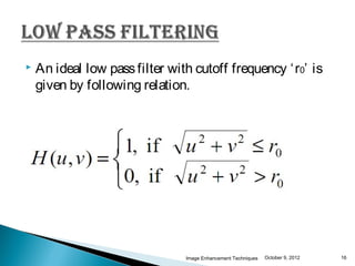
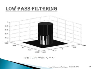
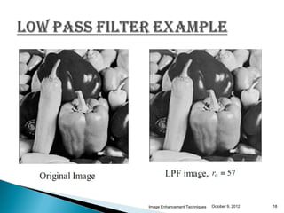
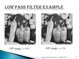
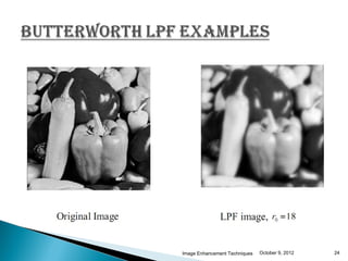
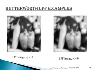
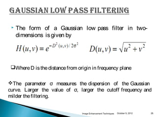
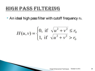
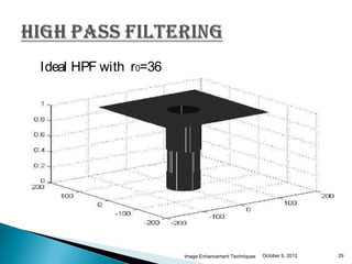
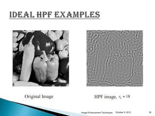
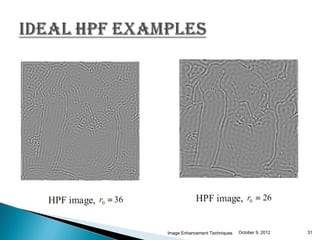
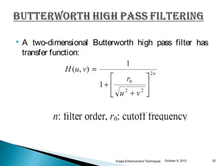
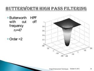
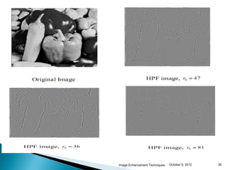
Presented by-:
Diwaker Pant
ME ECE Regular
   IntroductIon.

   Image enhancement.

   Frequency domaIn enhancement.

   Low pass FILterIng.

   hIgh pass FILterIng.

   concLusIon.

                           Image Enhancement Techniques   October 9, 2012   2
   Image enhancement is basically improving the
    interpretability or perception of information in images
    for human viewers and providing `better' input for
    other automated image processing techniques.

   The principal objective of image enhancement is to
    modify attributes of an image to make it more suitable
    for a given task and a specific observer.

   During this process, one or more attributes of the image
    are modified.

                                Image Enhancement Techniques   October 9, 2012   3
   There exist many techniques that can enhance a
    digital image without spoiling it.

   The enhancement methods can broadly be divided in
    to the following two categories:

   Spatial Domain Methods

Frequency     Domain Methods


                            Image Enhancement Techniques   October 9, 2012   4
   Unfortunately, there is no general theory for
    determining what is `good' image enhancement when it
    comes to human perception. If it looks good, it is good.

   However, when image enhancement techniques are
    used as pre-processing tools for other image processing
    techniques, then quantitative measures can determine
    which techniques are most appropriate.


                                Image Enhancement Techniques   October 9, 2012   5
Spatial Domain Methods
   In spatial domain techniques , we directly deal with the
    image pixels.

   The pixel values are manipulated to achieve desired
    enhancement.

   The value of a pixel with coordinates (x; y) in the
    enhanced image ‘ F’ is the result of performing some
    operation on the pixels in the neighborhood of (x; y) in
    the input image ‘ f’ .

                                Image Enhancement Techniques   October 9, 2012   6
   In frequency domain methods, the image is first
    transferred into frequency domain.

   It means that, the Fourier Transform of the image is
    computed first.

   All the enhancement operations are performed on the
    Fourier transform of the image and then the Inverse
    Fourier transform is performed to get the resultant
    image.


                              Image Enhancement Techniques   October 9, 2012   7
   These enhancement operations are performed in order
    to modify the image brightness, contrast or the
    distribution of the grey levels.

   As a consequence the pixel value (intensities) of the
    output image will be modified according to the
    transformation function applied on the input values.

   Image enhancement is applied in every field for
    example medical image analysis, analysis of images
    from satellites etc.

                              Image Enhancement Techniques   October 9, 2012   8
   Image enhancement simply means, transforming an
    image F into image G using T. (Where T is the
    transformation function.

   The values of pixels in images F and G are denoted by
     r and s, respectively. As said, the pixel values r and s
    are related by the expression
                            s= T(r)

 Where T     is a transformation that maps a pixel value r
    into a pixel value s.
                                Image Enhancement Techniques   October 9, 2012   9
Fourier                                                           Inverse Fourier
                         Filter Function
 Transform                                                            Transform
                              H(u,v)
   F(u,v)                                                               G(u,v)

                                            H(u,v)F(u,v)


   Pre-                                                                   Post-
processing                                                             Processing


Input Image                                                     Enhanced Image
  F(x,y)                                                           G(x,y)

              Frequency domain filtering operations
                                     Image Enhancement Techniques   October 9, 2012   10
   We can therefore directly design a transfer function
    and implement the enhancement in the frequency
    domain as follows.


                              Image Enhancement Techniques   October 9, 2012   11
   The concept of filtering is easier to visualize in the
    frequency domain.

   Therefore, enhancement of image can be done in the
    frequency domain, based on its DFT.


                               Image Enhancement Techniques   October 9, 2012   12
   Filtering can be divided in two categories namely

 Low     pass filtering

 High Pass filtering


                               Image Enhancement Techniques   October 9, 2012   13
   Edges and sharp transitions in gray values in an image
    contribute significantly to high-frequency content of its
    Fourier transform.

   Regions of relatively uniform gray values in an image
    contribute to low-frequency content of its Fourier
    transform.


                                Image Enhancement Techniques   October 9, 2012   14
   Hence, an image can be smoothed in the Frequency
    domain by attenuating the high-frequency content of its
    Fourier transform.

   This would be a low pass filter.

    For simplicity, we will consider only those filters that
    are real and symmetric.


                                Image Enhancement Techniques   October 9, 2012   15
   An ideal low pass filter with cutoff frequency ‘ r0’ is
    given by following relation.



                                Image Enhancement Techniques   October 9, 2012   16
Image Enhancement Techniques   October 9, 2012   17
Image Enhancement Techniques   October 9, 2012   18
Image Enhancement Techniques   October 9, 2012   19
 The cutofffrequency of the ideal LPF determines the
 amount of frequency components passed by the filter.

 Smaller
        the value of r0 , more the number of image
 components eliminated by the filter.

 In
   general, the value of r0 is chosen such that most
 components of interest are passed through, while
 most components not of interest are eliminated.


                           Image Enhancement Techniques   October 9, 2012   20
   A two-dimensional Butterworth low pass filter has
    transfer function:


                            Image Enhancement Techniques   October 9, 2012   21
Image Enhancement Techniques   October 9, 2012   22
   Frequency response does not                 have a sharp
    transition as in the ideal LPF.

   This is more appropriate for image smoothing than
    the ideal LPF, since this not introduce ringing.


                            Image Enhancement Techniques   October 9, 2012   23
Image Enhancement Techniques   October 9, 2012   24
Image Enhancement Techniques   October 9, 2012   25
   The form of a Gaussian low pass filter in two-
     dimensions is given by


 Where D is the distance from origin in frequency plane


The parameter σ measures the dispersion of the Gaussian
curve. Larger the value of σ, larger the cutoff frequency and
milder the filtering.


                                 Image Enhancement Techniques   October 9, 2012   26
   Hence, an image can be smoothed in the Frequency
    domain by attenuating the low-frequency content of its
    Fourier transform.

   This would be a high pass filter.

    For simplicity, we will consider only those filters that
    are real and symmetric


                                Image Enhancement Techniques   October 9, 2012   27
   An ideal high pass filter with cutoff frequency r0.


                                Image Enhancement Techniques   October 9, 2012   28
Ideal HPF with r0=36


                       Image Enhancement Techniques   October 9, 2012   29
Image Enhancement Techniques   October 9, 2012   30
Image Enhancement Techniques   October 9, 2012   31
   A two-dimensional Butterworth high pass filter has
    transfer function:


                             Image Enhancement Techniques   October 9, 2012   32
 Butterworth   HPF
 with     cut    off
 frequency
    r0=47

 Order   =2


                       Image Enhancement Techniques   October 9, 2012   33
   Frequency response does not                    have a sharp
    transition as in the ideal HPF.

   This is more appropriate for image sharpening than
    the ideal HPF, since this not introduce ringing.

   Example of Butterworth high pass filtering is given on
    next slide.


                               Image Enhancement Techniques   October 9, 2012   34
Image Enhancement Techniques   October 9, 2012   35
   Image enhancement algorithms offer a wide variety of
    approaches for modifying images to achieve visually
    acceptable images.

    The choice of such techniques is a function of the
    specific task, image content, observer characteristics,
    and viewing conditions.


                               Image Enhancement Techniques   October 9, 2012   36
   Raman Maini and Himanshu Aggarwal, “ A Comprehensive Review of
       Image Enhancement techniques” JOURNAL OF COMPUTING,
       VOLUME 2, ISSUE 3, MARCH 2010, ISSN 2151-9617 .

      Rafael C. Gonzalez and Richard E. Woods, digital Image Processing, 3rd
       Edition, Pearson Education, Boston, 2005, p200-300.

      MARIA ANGELA FRANCESCHINI, “ Frequency-domain techniques
       enhance optical mammography: Initial clinical results” , Publication Year:
       November 15, 1996.

       en.wikipedia.org


October 9, 2012                                                Image Enhancement Techniques   37
Image Enhancement Techniques   October 9, 2012   38

Frequency Domain Image Enhancement Techniques

  • 1.
  • 2.
    IntroductIon.  Image enhancement.  Frequency domaIn enhancement.  Low pass FILterIng.  hIgh pass FILterIng.  concLusIon. Image Enhancement Techniques October 9, 2012 2
  • 3.
    Image enhancement is basically improving the interpretability or perception of information in images for human viewers and providing `better' input for other automated image processing techniques.  The principal objective of image enhancement is to modify attributes of an image to make it more suitable for a given task and a specific observer.  During this process, one or more attributes of the image are modified. Image Enhancement Techniques October 9, 2012 3
  • 4.
    There exist many techniques that can enhance a digital image without spoiling it.  The enhancement methods can broadly be divided in to the following two categories:  Spatial Domain Methods Frequency Domain Methods Image Enhancement Techniques October 9, 2012 4
  • 5.
    Unfortunately, there is no general theory for determining what is `good' image enhancement when it comes to human perception. If it looks good, it is good.  However, when image enhancement techniques are used as pre-processing tools for other image processing techniques, then quantitative measures can determine which techniques are most appropriate. Image Enhancement Techniques October 9, 2012 5
  • 6.
    Spatial Domain Methods  In spatial domain techniques , we directly deal with the image pixels.  The pixel values are manipulated to achieve desired enhancement.  The value of a pixel with coordinates (x; y) in the enhanced image ‘ F’ is the result of performing some operation on the pixels in the neighborhood of (x; y) in the input image ‘ f’ . Image Enhancement Techniques October 9, 2012 6
  • 7.
    In frequency domain methods, the image is first transferred into frequency domain.  It means that, the Fourier Transform of the image is computed first.  All the enhancement operations are performed on the Fourier transform of the image and then the Inverse Fourier transform is performed to get the resultant image. Image Enhancement Techniques October 9, 2012 7
  • 8.
    These enhancement operations are performed in order to modify the image brightness, contrast or the distribution of the grey levels.  As a consequence the pixel value (intensities) of the output image will be modified according to the transformation function applied on the input values.  Image enhancement is applied in every field for example medical image analysis, analysis of images from satellites etc. Image Enhancement Techniques October 9, 2012 8
  • 9.
    Image enhancement simply means, transforming an image F into image G using T. (Where T is the transformation function.  The values of pixels in images F and G are denoted by r and s, respectively. As said, the pixel values r and s are related by the expression s= T(r)  Where T is a transformation that maps a pixel value r into a pixel value s. Image Enhancement Techniques October 9, 2012 9
  • 10.
    Fourier Inverse Fourier Filter Function Transform Transform H(u,v) F(u,v) G(u,v) H(u,v)F(u,v) Pre- Post- processing Processing Input Image Enhanced Image F(x,y) G(x,y) Frequency domain filtering operations Image Enhancement Techniques October 9, 2012 10
  • 11.
    We can therefore directly design a transfer function and implement the enhancement in the frequency domain as follows. Image Enhancement Techniques October 9, 2012 11
  • 12.
    The concept of filtering is easier to visualize in the frequency domain.  Therefore, enhancement of image can be done in the frequency domain, based on its DFT. Image Enhancement Techniques October 9, 2012 12
  • 13.
    Filtering can be divided in two categories namely  Low pass filtering  High Pass filtering Image Enhancement Techniques October 9, 2012 13
  • 14.
    Edges and sharp transitions in gray values in an image contribute significantly to high-frequency content of its Fourier transform.  Regions of relatively uniform gray values in an image contribute to low-frequency content of its Fourier transform. Image Enhancement Techniques October 9, 2012 14
  • 15.
    Hence, an image can be smoothed in the Frequency domain by attenuating the high-frequency content of its Fourier transform.  This would be a low pass filter.  For simplicity, we will consider only those filters that are real and symmetric. Image Enhancement Techniques October 9, 2012 15
  • 16.
    An ideal low pass filter with cutoff frequency ‘ r0’ is given by following relation.  Image Enhancement Techniques October 9, 2012 16
  • 17.
    Image Enhancement Techniques October 9, 2012 17
  • 18.
    Image Enhancement Techniques October 9, 2012 18
  • 19.
    Image Enhancement Techniques October 9, 2012 19
  • 20.
     The cutofffrequencyof the ideal LPF determines the amount of frequency components passed by the filter.  Smaller the value of r0 , more the number of image components eliminated by the filter.  In general, the value of r0 is chosen such that most components of interest are passed through, while most components not of interest are eliminated. Image Enhancement Techniques October 9, 2012 20
  • 21.
    A two-dimensional Butterworth low pass filter has transfer function: Image Enhancement Techniques October 9, 2012 21
  • 22.
    Image Enhancement Techniques October 9, 2012 22
  • 23.
    Frequency response does not have a sharp transition as in the ideal LPF.  This is more appropriate for image smoothing than the ideal LPF, since this not introduce ringing. Image Enhancement Techniques October 9, 2012 23
  • 24.
    Image Enhancement Techniques October 9, 2012 24
  • 25.
    Image Enhancement Techniques October 9, 2012 25
  • 26.
    The form of a Gaussian low pass filter in two- dimensions is given by Where D is the distance from origin in frequency plane The parameter σ measures the dispersion of the Gaussian curve. Larger the value of σ, larger the cutoff frequency and milder the filtering. Image Enhancement Techniques October 9, 2012 26
  • 27.
    Hence, an image can be smoothed in the Frequency domain by attenuating the low-frequency content of its Fourier transform.  This would be a high pass filter.  For simplicity, we will consider only those filters that are real and symmetric Image Enhancement Techniques October 9, 2012 27
  • 28.
    An ideal high pass filter with cutoff frequency r0. Image Enhancement Techniques October 9, 2012 28
  • 29.
    Ideal HPF withr0=36 Image Enhancement Techniques October 9, 2012 29
  • 30.
    Image Enhancement Techniques October 9, 2012 30
  • 31.
    Image Enhancement Techniques October 9, 2012 31
  • 32.
    A two-dimensional Butterworth high pass filter has transfer function: Image Enhancement Techniques October 9, 2012 32
  • 33.
     Butterworth HPF with cut off frequency r0=47  Order =2 Image Enhancement Techniques October 9, 2012 33
  • 34.
    Frequency response does not have a sharp transition as in the ideal HPF.  This is more appropriate for image sharpening than the ideal HPF, since this not introduce ringing.  Example of Butterworth high pass filtering is given on next slide. Image Enhancement Techniques October 9, 2012 34
  • 35.
    Image Enhancement Techniques October 9, 2012 35
  • 36.
    Image enhancement algorithms offer a wide variety of approaches for modifying images to achieve visually acceptable images.  The choice of such techniques is a function of the specific task, image content, observer characteristics, and viewing conditions. Image Enhancement Techniques October 9, 2012 36
  • 37.
    Raman Maini and Himanshu Aggarwal, “ A Comprehensive Review of Image Enhancement techniques” JOURNAL OF COMPUTING, VOLUME 2, ISSUE 3, MARCH 2010, ISSN 2151-9617 .  Rafael C. Gonzalez and Richard E. Woods, digital Image Processing, 3rd Edition, Pearson Education, Boston, 2005, p200-300.  MARIA ANGELA FRANCESCHINI, “ Frequency-domain techniques enhance optical mammography: Initial clinical results” , Publication Year: November 15, 1996.  en.wikipedia.org October 9, 2012 Image Enhancement Techniques 37
  • 38.
    Image Enhancement Techniques October 9, 2012 38