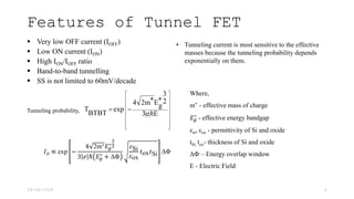
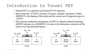
Tunnel Field Effect Transistor (TFET) is a gated reverse biased p-i-n structure characterized by band-to-band tunneling for current conduction, unlike MOSFETs which use thermionic emission. Key features of TFET include very low off current, low on current, high ion/ioff ratio, and subthreshold swing not limited to 60 mV/decade. The tunneling current is notably sensitive to the effective mass of charge carriers and other parameters such as the energy bandgap.

![Subthreshold Swing (SS)
28-06-2024 5
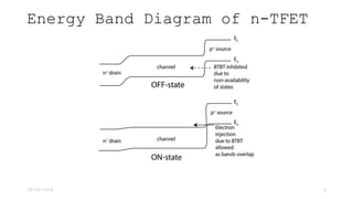
Transfer char. of MOSFET and Tunnel FET
[Ionescu A.M et al., Nature, 2011]
In a MOSFET,
SS = 1 +
𝐶𝑑
𝐶𝑜𝑥
ln(10)
𝑘𝑇
𝑞
SS ≈ 60 mV/decade @ 300 K
Subthreshold Swing (SS)=
𝑑𝑉𝐺𝑆
𝑑𝑙𝑜𝑔10𝐼𝐷
Subthreshold Slope =
1
𝑆𝑢𝑏𝑡ℎ𝑟𝑒𝑠ℎ𝑜𝑙𝑑 𝑆𝑤𝑖𝑛𝑔
due to Boltzmann distribution of charge carriers.](https://image.slidesharecdn.com/introductiontotunnelfieldeffecttransistor-240708055550-2442d8c0/85/Introduction-to-Tunnel-Field-Effect-Transistor-pptx-5-320.jpg)