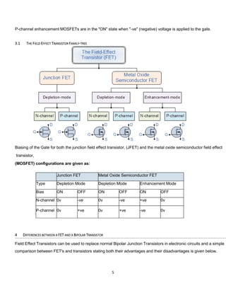
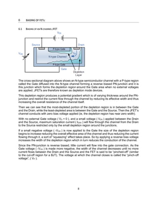
SlideShare a Scribd company logo
1 of 22
Download to read offline
Z
DIGITAL & ANALOUG
ELECTRONICS
Assignement#2
ABSTRACT
This File is about the comparison between BJTs, FETs &
its types, Transfer & Drain characteristics, applications
of BJTs, FETs & its different configurations.
Prepared by:
MUHAMMAD NUMAN
(2016-UET-CCET-ELECT-01)
Submitted to:
Dr. TOUSEEF
CHENAB COLLEGE OF ENGINEERING &
TECHNOLOGY GUJRANWALA
1
2
Contents
2 Bipolar Junction Transistor (BJT).......................................................................................................3
3 Field Effect Transistor ...........................................................................................................................4
3.1 The Field Effect Transistor Family-tree.........................................................................................5
4 Differences between a FET and a Bipolar Transistor............................................................................5
4.1.1 Comparison of Connections between a JFET and a BJT........................................................6
5 DIAGRAMS OF BJT & FETS:....................................................................................................................7
6 BIASING OF FETs: ..................................................................................................................................8
6.1 Biasing of an N-channel JFET.........................................................................................................8
6.2 JFET Channel Pinched-off..............................................................................................................9
7 Output characteristic V-I curves of a typical junction FET..................................................................10
• Ohmic Region..............................................................................................................................10
• Cut-off Region.............................................................................................................................10
• Saturation or Active Region ........................................................................................................10
7.1 Drain current in the active region...............................................................................................11
7.2 Drain-Source channel resistance. ...............................................................................................11
8 CHARACTERISTICS OF JFETS................................................................................................................11
8.1 Output or Drain Characteristic....................................................................................................11
8.1.1 Drain Characteristic With Shorted-Gate.............................................................................12
8.1.2 Drain Characteristics With External Bias:............................................................................13
8.1.3 External-Bias-Characteristic-of-JFET ...................................................................................13
8.2 Transfer Characteristic of JFET....................................................................................................14
9 Modes of FET’s....................................................................................................................................15
9.1 Common Source (CS) Configuration ...........................................................................................16
9.2 Common Gate (CG) Configuration..............................................................................................16
9.3 Common Drain (CD) Configuration.............................................................................................17
10 The JFET Amplifier...........................................................................................................................17
10.1 Biasing of JFET Amplifier.............................................................................................................17
11 Applications of Field Effect Transistor ............................................................................................18
11.1 Analog Switches.......................................................................................................................18
11.2 Amplifiers...................................................................................................................................19
11.3 Phase Shift Oscillator ..................................................................................................................20
11.4 Chopper .....................................................................................................................................20
3
11.5 Current Limiter..........................................................................................................................21
2 BIPOLAR JUNCTION TRANSISTOR (BJT)
The Bipolar Junction Transistor (BJT) is a three layer device constructed form two
semiconductor diode junctions joined together, one forward biased and one reverse biased.
Types:
There are two main types of bipolar junction transistors, the NPN and the PNP transistor.
The Bipolar Junction Transistor (BJT) is a three layer device constructed form two semiconductor diode
junctions joined together, one forward biased and one reverse biased.
There are two main types of bipolar junction transistors, the NPN and the PNP transistor.
Transistors are "Current Operated Devices" where a much smaller Base current causes a larger Emitter to
Collector current, which themselves are nearly equal, to flow.
The arrow in a transistor symbol represents conventional current flow.
The most common transistor connection is the Common-emitter configuration.
Requires a Biasing voltage for AC amplifier operation.
The Base-Emitter junction is always forward biased whereas the Collector-Base junction is always reverse
biased.
The standard equation for currents flowing in a transistor is given as: IE = IB + Ic
The Collector or output characteristics curves can be used to find either Ib, Ic or β to which a load line can be
constructed to determine a suitable operating point, Q with variations in base current determining the operating
range.
4
A transistor can also be used as an electronic switch to control devices such as lamps, motors and solenoids etc.
Inductive loads such as DC motors, relays and solenoids require a reverse biased "Flywheel" diode placed
across the load. This helps prevent any induced back emf's generated when the load is switched "OFF" from
damaging the transistor.
The NPN transistor requires the Base to be more positive than the Emitter while the PNP type requires
that the Emitter is more positive than the Base.
3 FIELD EFFECT TRANSISTOR
Field Effect Transistors, or FET's are "Voltage Operated Devices" and can be divided into two main types:
Junction-gate devices called JFET's and Insulated-gate devices called IGFET´s or more commonly known as
MOSFETs.
Insulated-gate devices can also be sub-divided into Enhancement types and Depletion types. All forms are
available in both N-channel and P-channel versions.
FET's have very high input resistances so very little or no current (MOSFET types) flows into the input
terminal making them ideal for use as electronic switches.
The input impedance of the MOSFET is even higher than that of the JFET due to the insulating oxide layer
and therefore static electricity can easily damage MOSFET devices so care needs to be taken when handling
them.
When no voltage is applied to the gate of an enhancement FET the transistor is in the "OFF" state similar to
an "open switch".
The depletion FET is inherently conductive and in the "ON" state when no voltage is applied to the gate
similar to a "closed switch".
FET's have very large current gain compared to junction transistors.
They can be used as ideal switches due to their very high channel "OFF" resistance, low "ON" resistance.
To turn the N-channel JFET transistor "OFF", a negative voltage must be applied to the gate.
To turn the P-channel JFET transistor "OFF", a positive voltage must be applied to the gate.
N-channel depletion MOSFETs are in the "OFF" state when a negative voltage is applied to the gate to create
the depletion region.
P-channel depletion MOSFETs, are in the "OFF" state when a positive voltage is applied to the gate to create
the depletion region.
N-channel enhancement MOSFETs are in the "ON" state when a "+ve" (positive) voltage is applied to the
gate.
5
P-channel enhancement MOSFETs are in the "ON" state when "-ve" (negative) voltage is applied to the gate.
3.1 THE FIELD EFFECT TRANSISTOR FAMILY-TREE
Biasing of the Gate for both the junction field effect transistor, (JFET) and the metal oxide semiconductor field effect
transistor,
(MOSFET) configurations are given as:
Junction FET Metal Oxide Semiconductor FET
Type Depletion Mode Depletion Mode Enhancement Mode
Bias ON OFF ON OFF ON OFF
N-channel 0v -ve 0v -ve +ve 0v
P-channel 0v +ve 0v +ve -ve 0v
4 DIFFERENCES BETWEEN A FET AND A BIPOLAR TRANSISTOR
Field Effect Transistors can be used to replace normal Bipolar Junction Transistors in electronic circuits and a simple
comparison between FET's and transistors stating both their advantages and their disadvantages is given below.
6
Field Effect Transistor (FET) Bipolar Junction Transistor (BJT)
1 Low voltage gain High voltage gain
2 High current gain Low current gain
3 Very input impedance Low input impedance
4 High output impedance Low output impedance
5 Low noise generation Medium noise generation
6 Fast switching time Medium switching time
7 Easily damaged by static Robust
8 Some require an input to turn it "OFF" Requires zero input to turn it "OFF"
9 Voltage controlled device Current controlled device
10 Exhibits the properties of a Resistor
11 More expensive than bipolar Cheap
12 Difficult to bias Easy to bias
4.1.1 Comparison of Connections between a JFET and a BJT
Bipolar Transistor (BJT) Field Effect Transistor (FET)
Emitter – (E) >> Source – (S)
Base – (B) >> Gate – (G)
Collector – (C) >> Drain – (D)
7
5 DIAGRAMS OF BJT & FETS:
FET DIAGRAMS:
BJT DIAGRAMS:
8
6 BIASING OF FETs:
6.1 BIASING OF AN N-CHANNEL JFET
The cross sectional diagram above shows an N-type semiconductor channel with a P-type region
called the Gate diffused into the N-type channel forming a reverse biased PN-junction and it is
this junction which forms the depletion region around the Gate area when no external voltages
are applied. JFETs are therefore known as depletion mode devices.
This depletion region produces a potential gradient which is of varying thickness around the PN-
junction and restrict the current flow through the channel by reducing its effective width and thus
increasing the overall resistance of the channel itself.
Then we can see that the most-depleted portion of the depletion region is in between the Gate
and the Drain, while the least-depleted area is between the Gate and the Source. Then the JFET’s
channel conducts with zero bias voltage applied (ie, the depletion region has near zero width).
With no external Gate voltage ( VG = 0 ), and a small voltage ( VDS ) applied between the Drain
and the Source, maximum saturation current ( IDSS ) will flow through the channel from the Drain
to the Source restricted only by the small depletion region around the junctions.
If a small negative voltage ( -VGS ) is now applied to the Gate the size of the depletion region
begins to increase reducing the overall effective area of the channel and thus reducing the current
flowing through it, a sort of “squeezing” effect takes place. So by applying a reverse bias voltage
increases the width of the depletion region which in turn reduces the conduction of the channel.
Since the PN-junction is reverse biased, little current will flow into the gate connection. As the
Gate voltage ( -VGS ) is made more negative, the width of the channel decreases until no more
current flows between the Drain and the Source and the FET is said to be “pinched-off” (similar
to the cut-off region for a BJT). The voltage at which the channel closes is called the “pinch-off
voltage”, ( VP ).
9
6.2 JFET CHANNEL PINCHED-OFF
In this pinch-off region the Gate voltage, VGS controls the channel current and VDS has little or no
effect.
JFET Model
The result is that the FET acts more like a voltage controlled resistor which has zero resistance
when VGS = 0 and maximum “ON” resistance ( RDS ) when the Gate voltage is very negative.
Under normal operating conditions, the JFET gate is always negatively biased relative to the
source.
It is essential that the Gate voltage is never positive since if it is all the channel current will flow to
the Gate and not to the Source, the result is damage to the JFET. Then to close the channel:
• No Gate Voltage ( VGS ) and VDS is increased from zero.
• No VDS and Gate control is decreased negatively from zero.
• VDS and VGS varying.
The P-channel Junction Field Effect Transistor operates exactly the same as the N-channel
above, with the following exceptions: 1). Channel current is positive due to holes, 2). The polarity
of the biasing voltage needs to be reversed.
10
7 OUTPUT CHARACTERISTIC V-I CURVES OF A TYPICAL JUNCTION FET
The voltage VGS applied to the Gate controls the current flowing between the Drain and the Source
terminals. VGS refers to the voltage applied between the Gate and the Source while VDS refers to
the voltage applied between the Drain and the Source.
Because a Junction Field Effect Transistor is a voltage controlled device, “NO current flows
into the gate!” then the Source current ( IS ) flowing out of the device equals the Drain current
flowing into it and therefore ( ID = IS ).
The characteristics curves example shown above, shows the four different regions of operation
for a JFET and these are given as:
• OHMIC REGION – When VGS = 0 the depletion layer of the channel is very small and the JFET
acts like a voltage controlled resistor.
• CUT-OFF REGION – This is also known as the pinch-off region were the Gate voltage, VGS is
sufficient to cause the JFET to act as an open circuit as the channel resistance is at
maximum.
• SATURATION OR ACTIVE REGION – The JFET becomes a good conductor and is controlled by the
Gate-Source voltage, ( VGS ) while the Drain-Source voltage, ( VDS) has little or no effect.
11
• Breakdown Region – The voltage between the Drain and the Source, ( VDS ) is high
enough to causes the JFET’s resistive channel to break down and pass uncontrolled
maximum current.
The characteristics curves for a P-channel junction field effect transistor are the same as those
above, except that the Drain current ID decreases with an increasing positive Gate-Source
voltage, VGS.
The Drain current is zero when VGS = VP. For normal operation, VGS is biased to be somewhere
between VP and 0. Then we can calculate the Drain current, ID for any given bias point in the
saturation or active region as follows:
7.1 DRAIN CURRENT IN THE ACTIVE REGION.
Note that the value of the Drain current will be between zero (pinch-off) and IDSS(maximum
current). By knowing the Drain current ID and the Drain-Source voltage VDSthe resistance of the
channel ( ID ) is given as:
7.2 DRAIN-SOURCE CHANNEL RESISTANCE.
Where: gm is the “transconductance gain” since the JFET is a voltage controlled device and which
represents the rate of change of the Drain current with respect to the change in Gate-Source
voltage.
8 CHARACTERISTICS OF JFETS
There are two types of static characteristics viz
(1) Output or drain characteristic and
(2) Transfer characteristic.
8.1 OUTPUT OR DRAIN CHARACTERISTIC.
The curve drawn between drain current Ip and drain-source voltage VDS with gate-to source
voltage VGS as the parameter is called the drain or output characteristic. This characteristic is
analogous to collector characteristic of a BJT:
12
8.1.1 Drain Characteristic With Shorted-Gate
The circuit diagram for determining the drain characteristic with shorted-gate for an N-channel
JFET is given in figure. and the drain characteristic with shorted-gate is shown in another figure.
Initially when drain-source voltage Vns is zero, there is no attracting potential at the drain, so no
current flows inspite of the fact that the channel is fully open. This gives drain current Ip = 0. For
small applied voltage Vna, the N-type bar acts as a simple semiconductor resistor, and the drain
current increases linearly with_the increase in Vds, upto the knee point. This region, (to the left of
the knee point) of the curve is called the channel ohmic region, because in this region the FET
behaves like an ordinary resistor.
With the increase in drain current ID, the ohmic voltage drop between the source and channel
region reverse-biases the gate junction. The reverse-biasing of the gate junction is not uniform
throughout., The reverse bias is more at the drain end than that at the source end of the channel,
so with the increase in Vds, the conducting portion of the channel begins to constrict more at the
drain end. Eventually a voltage Vds is reached at which the channel is pinched off. The drain
current ID no longer increases with the increase in Vds. It approaches a constant saturation value.
The value of voltage VDS at which the channel is pinched off (i.e. all the free charges from the
channel get removed), is called the pinch-off voltage Vp. The pinch-off voltage Vp, not too sharply
defined on the curve, where the drain current ID begins to level off and attains a constant value.
From point A (knee point) to the point B (pinch-off point) the drain current ID increases with the
increase In voltage Vdsfollowing a reverse square law. The region of the characteristic in which
drain current IDremains fairly constant is called the pinch-off region. It is also sometimes called
the saturation region or amplifier region. In this region the JFET operates as a constant
current device sincedrain current (or output current) remains almost constant. It is the normal
operating region of the JFET when used as an amplifier. The drain current in the pinch-off region
with VGS = 0 is referred to the drain-source saturation current, Idss).
13
It is to be noted that in the pinch-off (or saturation) region the channel resistance increases in
proportion to increase in VDS and so keeps the drain current almost constant and the reverse bias
required by the gate-channel junction is supplied entirely by the voltage drop across the channel
resistance due to flow of IDsg and not by the external bias because VGS = 0
Drain current in the pinch-of region is given by Shockley’s equation
where ID is the drain current at a given gate-source voltage VGS, IDSS is the drain-current with gate
shorted to source and VGS (0FF) is the gate-source cut-off voltage.
If drain-source voltage, Vds is continuously increased, a stage comes when the gate-channel
junction breaksdown. At this point current increases very rapidly. and the JFET may be destroyed.
This happens because the charge carriers making up the saturation current at the gate channel
junction accelerate to a high velocity and produce an avalanche effect.
8.1.2 Drain Characteristics With External Bias:
The circuit diagram for determining the drain characteristics with different values of external bias
is shown in figure. and a family of drain characteristics for different values of gate-source voltage
VGS is given in next figure
8.1.3 External-Bias-Characteristic-of-JFET
It is observed that as the negative gate bias voltage is increased
(1) The maximum saturation drain current becomes smaller because the conducting channel now
becomes narrower.
14
(2) Pinch-off voltage is reached at a lower value of drain current ID than when VGS = 0. When an
external bias of, say – 1 V is applied between the gate and the source, the gate-channel junctions
are reverse-biased even when drain current, ID is zero. Hence the depletion regions are already
penetrating the channel to a certain extent when drain-| source voltage, VDS is zero. Due to this
reason, a smaller voltage drop along the channel (i.e. smaller than that for VGS = 0) will increase
the depletion regions to the point where 1 they pinch-off the current. Consequently, the pinch-off
voltage VP is reached at a lower 1 drain current, ID when VGS = 0.
(3) The ohmic region portion decreases.
(4) Value of drain-source voltage VDS for the avalanche breakdown of the gate junction is reduced.
Value of drain-source voltage, VDS for breakdown with the increase in negative bias voltage is
reduced simply due to the fact that gate-source voltage, VGS keeps adding to the I reverse bias at
the junction produced by current flow. Thus the maximum value of VDS I that can be applied to a FET is the lowest
voltage which causes avalanche breakdown. It is also observed that with VGS = 0, ID saturates at IDSS and the characteristic shows VP = 4 V. When
an external bias of – 1 V is applied, the gate-channel junctions still require -4 V to achieve pinch-off. It means that a 3 V drop is now required along the
channel instead of the previous 4.0 V. Obviously, this drop of 3 V can be achieved with a lowervalue of drain current, Similarly when VGS = – 2 V and –
3 V, pinch-off is achieved with 2 V and 1 V respectively, along the channel. These drops of 2 V and 1 V are, of course, achieved with further reduced
values of drain current, ID. It is further observed that when the gate-source bias is numerically equal to pinch-off voltage, VP (-4 V in this case), no channel
drop is required and, therefore, drain current, ID is zero. The gate-source bias voltage required to reduce drain current, ID to zero is designated the gate-
source cut-off voltage, VGS /0FF) and, as explained,
Hence for working of JFET in the pinch-off or active region it is necessary that the following
conditions be fulfilled.
VP < VDS < VDS (max)
VGS (OFF)< VGS < 0
0 < ID < IDSS
8.2 TRANSFER CHARACTERISTIC OF JFET
The transfer characteristic for a JFET can be determined experimentally, keeping drain-source
voltage, VDS constant and determining drain current, ID for various values of gate-source voltage,
VGS. The circuit diagram is shown in fig. 9.7 (a). The curve is plotted between gate-source voltage,
15
VGS and drain current, ID, as illustrated in fig. 9.8. It is similarto the transconductance
characteristic of a vacuum tube or a transistor. It is observed that
(i) Drain current decreases with the increase in negative gate-source bias
(ii) Drain current, ID = IDSS when VGS = 0
(iii) Drain current, ID = 0 when VGS = VD The transfer characteristic follows equation (9.1)
The transfer characteristic can also be derived from the drain characteristic by noting
values of drain current, IDcorresponding to various values of gate-source voltage, VGS for a
constant drain-source voltage and plotting them.
It may be noted that a P-channel JFET operates in the same way and have the similar
characteristics as an N-channel JFET except that channel carriers are holes instead of electrons
and the polarities of VGS and VDS are reversed.
9 MODES OF FET’S
Like the bipolar junction transistor, the field effect transistor being a three terminal device is
capable of three distinct modes of operation and can therefore be connected within a circuit in
one of the following configurations.
16
9.1 COMMON SOURCE (CS) CONFIGURATION
In the Common Source configuration (similar to common emitter), the input is applied to the Gate
and its output is taken from the Drain as shown. This is the most common mode of operation of
the FET due to its high input impedance and good voltage amplification and as such Common
Source amplifiers are widely used.
The common source mode of FET connection is generally used audio frequency amplifiers and
in high input impedance pre-amps and stages. Being an amplifying circuit, the output signal is
180o
“out-of-phase” with the input.
9.2 COMMON GATE (CG) CONFIGURATION
In the Common Gate configuration (similar to common base), the input is applied to the Source
and its output is taken from the Drain with the Gate connected directly to ground (0v) as shown.
The high input impedance feature of the previous connection is lost in this configuration as the
common gate has a low input impedance, but a high output impedance.
This type of FET configuration can be used in high frequency circuits or in impedance matching
circuits were a low input impedance needs to be matched to a high output impedance. The output
is “in-phase” with the input.
17
9.3 COMMON DRAIN (CD) CONFIGURATION
In the Common Drain configuration (similar to common collector), the input is applied to the Gate
and its output is taken from the Source. The common drain or “source follower” configuration has
a high input impedance and a low output impedance and near-unity voltage gain so is therefore
used in buffer amplifiers. The voltage gain of the source follower configuration is less than unity,
and the output signal is “in-phase”, 0o
with the input signal.
This type of configuration is referred to as “Common Drain” because there is no signal available
at the drain connection, the voltage present, +VDD just provides a bias. The output is in-phase with
the input.
10 THE JFET AMPLIFIER
Just like the bipolar junction transistor, JFET’s can be used to make single stage class A amplifier
circuits with the JFET common source amplifier and characteristics being very similar to the BJT
common emitter circuit. The main advantage JFET amplifiers have over BJT amplifiers is their
high input impedance which is controlled by the Gate biasing resistive network formed
by R1 and R2 as shown.
10.1 BIASING OF JFET AMPLIFIER
18
This common source (CS) amplifier circuit is biased in class “A” mode by the voltage divider
network formed by resistors R1 and R2. The voltage across the Source resistor RS is generally
set to be about one quarter of VDD, ( VDD /4 ) but can be any reasonable value.
The required Gate voltage can then be calculated from this RS value. Since the Gate current is
zero, (IG = 0) we can set the required DC quiescent voltage by the proper selection of
resistors R1 and R2.
The control of the Drain current by a negative Gate potential makes the Junction Field Effect
Transistor useful as a switch and it is essential that the Gate voltage is never positive for an N-
channel JFET as the channel current will flow to the Gate and not the Drain resulting in damage
to the JFET. The principals of operation for a P-channel JFET are the same as for the N-channel
JFET, except that the polarity of the voltages need to be reversed.
In the next tutorial about Transistors, we will look at another type of Field Effect Transistor called
a MOSFET whose Gate connection is completely isolated from the main current carrying channel.
11 APPLICATIONS OF FIELD EFFECT TRANSISTOR
11.1 ANALOG SWITCHES
The application of FETs as the switches in analog circuits is a direct consequence of their mode
of working. This is because when the Gate-Source voltage, VGS is zero, n-channel FET will
operate in saturation region and will act like (almost) a short circuit. Thus the output voltage will
be zero (Figure 1). On the other hand, if a negative voltage is applied between the gate and
source terminals i.e. if VGS is negative, then the FET operates in its cut-off or pinch-off region.
This means that, in this case, the FET acts like an open circuit and the drain current, ID will be
equal to zero. Due to this, the voltage across the load resistance RD will be zero which further
causes the VDD to appear at V0.
This property of JFET to behave like a switch can be exploited in order to design an Analog
Multiplexer as shown by Figure 2
19
Here each of the input signal (Signal 1, Signal 2, … Signal n) is made to pass through a dedicated
JFET (T1, T2, … Tn) before being connected to the output terminal, V0. Here only one signal among
the multiple input signals will appear at the output terminal depending on the voltages VGS at the
gate terminals of the FETs.
For example, if VGS2 is negative while all other VGS supplies are zero, then the output signal will
be Signal 2. Moreover the switching property of the Insulated Gate Bipolar Transistors (IGBTs) is
exploited in internal combustion engine ignition coils which demand for fast switching and voltage
blocking capabilities
.
11.2 AMPLIFIERS
Junction FETs (JFETs) are used in the stage of amplification which isolates the
previous stage from the next stage and thus act as buffer amplifiers (Figure 3). This is because,
JFETs have very high input impedance due to which the preceding stage will be lightly loaded
causing the entire output of Stage 1 to appear at the input of the buffer.
Further the entire buffer output can be made to appear at the input of the Stage 2 using JFETs in
Common Drain Configuration, due to the low output impedance offered. This even means that
the buffer amplifiers are capable of driving heavy loads or small load resistances.
FETs are
low noise devices when compared to Bipolar Junction Transistors (BJTs). This makes it a useful
component to be used as an amplifier at the receiver front-end as one needs the minimal amount
of noise at the final output. Further it is to be noted that JFETs are voltage controlled devices
which makes them ideal to be used as Radio Frequency (RF) amplifiers. The reason behind this
is, one expects the RF amplifier to respond appropriately even when the antennas at the receiver-
end receive the weak signals (signals with very low amount of current). A FET amplifier in common
source (CS) configuration can be used to drive another FET amplifier in common gate
configuration, forming a Cascode Amplifier as shown by Figure 4. Although the gain of the
20
Cascode amplifier is same to that of CS amplifier, its input capacitance is significantly low when
compared to that of CS amplifier. Moreover the Cascode amplifier offers a very high resistance
at its input.
11.3 Phase Shift Oscillator
JFETs offer high impedance at their input terminals which reduces the loading effect. Further the
y can be suitably used to accomplish both amplification as well as feedback functions. This nature
of FETs makes them suitable to be used in phase shift oscillator circuits as shown by Figure 5.
11.4 CHOPPER
JFET acting as a switch can be used as a chopper (Figure 6) wherein the DC voltage applied to
it, VDC is converted into AC voltage with the same amplitude level, VAC. This is due to the fact
that the square voltage waveform applied as the VGS causes the JFET to operate in cut-off and
saturation regions, alternately. Such chopper circuits aid to overcome the problem of drift which
exists in the case of direct-coupled amplifiers.
21
11.5 CURRENT LIMITER
A n-channel JFET whose Gate terminal is shorted with the Source terminal acts like a current
limiter. This means that in this arrangement, FETs allow the current through them to rise to only
a particular level after which it is maintained constant, irrespective of the fluctuations in the level
of voltage. These current limiters form an integral part of constant-current or current-regulator
diodes.
Apart from these, FETs are extensively used in Integrated Circuits (ICs) due to their compact size.
They are used in mixer circuits of TV and FM receivers due to low inter modulation distortions.
Moreover FETs are also used as voltage-variable resistors in OP-AMPS, tone control circuits and
JFET voltmeter design. JFETs can also be used to design the timer circuits as they offer high
isolation between their gate and drain terminals. Further, JFETs also find their usage in the fields
like digital electronics and fibre optic systems

More Related Content

What's hot

Classes of amplifier
Classes of amplifierClasses of amplifier
Classes of amplifierGaditek
 
Amplifier classes of operation and biasing networks latest
Amplifier classes of operation and biasing networks latestAmplifier classes of operation and biasing networks latest
Amplifier classes of operation and biasing networks latestHrudya Balachandran
 
Negative amplifiers and its types Positive feedback and Negative feedback
Negative amplifiers and its types Positive feedback  and Negative feedbackNegative amplifiers and its types Positive feedback  and Negative feedback
Negative amplifiers and its types Positive feedback and Negative feedbackimtiazalijoono
 
Class a amplifier
Class a amplifierClass a amplifier
Class a amplifierimSagi
 
Multi stage amp
Multi stage ampMulti stage amp
Multi stage ampsarunkutti
 
Direct coupled amplifier
Direct coupled amplifierDirect coupled amplifier
Direct coupled amplifierhome
 
Power amplifire analog electronics
Power amplifire analog electronicsPower amplifire analog electronics
Power amplifire analog electronicsrakesh mandiya
 
Amplifier (Transformer Coupled)
Amplifier (Transformer Coupled)Amplifier (Transformer Coupled)
Amplifier (Transformer Coupled)Arpan Bose
 
Amplifier classes explained
Amplifier classes explainedAmplifier classes explained
Amplifier classes explainedGaditek
 
Inverting Amplifier : Op-amp
Inverting Amplifier : Op-ampInverting Amplifier : Op-amp
Inverting Amplifier : Op-ampDoCircuits
 

What's hot (20)

transistor
transistortransistor
transistor
 
Class b amplifier
Class b amplifierClass b amplifier
Class b amplifier
 
Classes of amplifier
Classes of amplifierClasses of amplifier
Classes of amplifier
 
Amplifier classes of operation and biasing networks latest
Amplifier classes of operation and biasing networks latestAmplifier classes of operation and biasing networks latest
Amplifier classes of operation and biasing networks latest
 
Classes of amplifiers
Classes of amplifiersClasses of amplifiers
Classes of amplifiers
 
Negative amplifiers and its types Positive feedback and Negative feedback
Negative amplifiers and its types Positive feedback  and Negative feedbackNegative amplifiers and its types Positive feedback  and Negative feedback
Negative amplifiers and its types Positive feedback and Negative feedback
 
Bjt amplifiers
Bjt amplifiersBjt amplifiers
Bjt amplifiers
 
Class a amplifier
Class a amplifierClass a amplifier
Class a amplifier
 
Multi stage amp
Multi stage ampMulti stage amp
Multi stage amp
 
Direct coupled amplifier
Direct coupled amplifierDirect coupled amplifier
Direct coupled amplifier
 
Basics of amplifier
Basics of amplifierBasics of amplifier
Basics of amplifier
 
Power amplifire analog electronics
Power amplifire analog electronicsPower amplifire analog electronics
Power amplifire analog electronics
 
OpAmps
OpAmpsOpAmps
OpAmps
 
Amplifier (Transformer Coupled)
Amplifier (Transformer Coupled)Amplifier (Transformer Coupled)
Amplifier (Transformer Coupled)
 
Arvi
ArviArvi
Arvi
 
Transistor
TransistorTransistor
Transistor
 
Amplifier classes explained
Amplifier classes explainedAmplifier classes explained
Amplifier classes explained
 
Feedback in amplifier
Feedback in amplifierFeedback in amplifier
Feedback in amplifier
 
Amplifier
AmplifierAmplifier
Amplifier
 
Inverting Amplifier : Op-amp
Inverting Amplifier : Op-ampInverting Amplifier : Op-amp
Inverting Amplifier : Op-amp
 

Similar to Comparing BJTs, FETs, and their applications

B.e assignment 2-by_daniyal ali channa
B.e assignment 2-by_daniyal ali channaB.e assignment 2-by_daniyal ali channa
B.e assignment 2-by_daniyal ali channaDaniyal Channa
 
EE20-Chapter 5
EE20-Chapter 5 EE20-Chapter 5
EE20-Chapter 5 ruhiyah
 
electrical technology electrical technology
electrical technology electrical technologyelectrical technology electrical technology
electrical technology electrical technologysribalaji162407
 
Unit 5-BEE Electronics for Engineering in Computer branch 2nd sem diploma by ...
Unit 5-BEE Electronics for Engineering in Computer branch 2nd sem diploma by ...Unit 5-BEE Electronics for Engineering in Computer branch 2nd sem diploma by ...
Unit 5-BEE Electronics for Engineering in Computer branch 2nd sem diploma by ...raghavbairboyana6
 
Aim-to study characterstics of fet (field effect [Autosaved].pptx
Aim-to study characterstics of fet (field effect [Autosaved].pptxAim-to study characterstics of fet (field effect [Autosaved].pptx
Aim-to study characterstics of fet (field effect [Autosaved].pptxRandeepKaushik1
 
MOSFET INVERTER SIMULATION
MOSFET INVERTER SIMULATIONMOSFET INVERTER SIMULATION
MOSFET INVERTER SIMULATIONMOHAMMAD HANNAN
 
Transistor and it's working principle
Transistor and it's working principleTransistor and it's working principle
Transistor and it's working principleEkram Bin Mamun
 
transistoranditsworkingprinciple-160427150207 (1).pdf
transistoranditsworkingprinciple-160427150207 (1).pdftransistoranditsworkingprinciple-160427150207 (1).pdf
transistoranditsworkingprinciple-160427150207 (1).pdfrahulreddy773814
 
Field effect transistor
Field effect transistorField effect transistor
Field effect transistorAli Saeed
 
EDC UNIT 3 PPT.pptx
EDC UNIT 3 PPT.pptxEDC UNIT 3 PPT.pptx
EDC UNIT 3 PPT.pptxraghul443103
 
Field Effect Transistor ppt
Field Effect Transistor pptField Effect Transistor ppt
Field Effect Transistor pptSameeksha Verma
 

Similar to Comparing BJTs, FETs, and their applications (20)

B.e assignment 2-by_daniyal ali channa
B.e assignment 2-by_daniyal ali channaB.e assignment 2-by_daniyal ali channa
B.e assignment 2-by_daniyal ali channa
 
EE20-Chapter 5
EE20-Chapter 5 EE20-Chapter 5
EE20-Chapter 5
 
electrical technology electrical technology
electrical technology electrical technologyelectrical technology electrical technology
electrical technology electrical technology
 
Jfet knr
Jfet knrJfet knr
Jfet knr
 
Basic electronics
Basic electronicsBasic electronics
Basic electronics
 
JFET TRANSISTER with reference,working and conclusion
JFET TRANSISTER with reference,working and conclusionJFET TRANSISTER with reference,working and conclusion
JFET TRANSISTER with reference,working and conclusion
 
FET etc.pptx
FET etc.pptxFET etc.pptx
FET etc.pptx
 
Unit 5-BEE Electronics for Engineering in Computer branch 2nd sem diploma by ...
Unit 5-BEE Electronics for Engineering in Computer branch 2nd sem diploma by ...Unit 5-BEE Electronics for Engineering in Computer branch 2nd sem diploma by ...
Unit 5-BEE Electronics for Engineering in Computer branch 2nd sem diploma by ...
 
JFET
JFETJFET
JFET
 
Modes of transistor.pdf
Modes of transistor.pdfModes of transistor.pdf
Modes of transistor.pdf
 
MOSFET AND JFET
MOSFET AND JFETMOSFET AND JFET
MOSFET AND JFET
 
Aim-to study characterstics of fet (field effect [Autosaved].pptx
Aim-to study characterstics of fet (field effect [Autosaved].pptxAim-to study characterstics of fet (field effect [Autosaved].pptx
Aim-to study characterstics of fet (field effect [Autosaved].pptx
 
MOSFET INVERTER SIMULATION
MOSFET INVERTER SIMULATIONMOSFET INVERTER SIMULATION
MOSFET INVERTER SIMULATION
 
JFET
JFETJFET
JFET
 
Transistor and it's working principle
Transistor and it's working principleTransistor and it's working principle
Transistor and it's working principle
 
transistoranditsworkingprinciple-160427150207 (1).pdf
transistoranditsworkingprinciple-160427150207 (1).pdftransistoranditsworkingprinciple-160427150207 (1).pdf
transistoranditsworkingprinciple-160427150207 (1).pdf
 
Field effect transistor
Field effect transistorField effect transistor
Field effect transistor
 
EDC UNIT 3 PPT.pptx
EDC UNIT 3 PPT.pptxEDC UNIT 3 PPT.pptx
EDC UNIT 3 PPT.pptx
 
Transistors
TransistorsTransistors
Transistors
 
Field Effect Transistor ppt
Field Effect Transistor pptField Effect Transistor ppt
Field Effect Transistor ppt
 

Recently uploaded

High Profile Call Girls Nagpur Isha Call 7001035870 Meet With Nagpur Escorts
High Profile Call Girls Nagpur Isha Call 7001035870 Meet With Nagpur EscortsHigh Profile Call Girls Nagpur Isha Call 7001035870 Meet With Nagpur Escorts
High Profile Call Girls Nagpur Isha Call 7001035870 Meet With Nagpur Escortsranjana rawat
 
Decoding Kotlin - Your guide to solving the mysterious in Kotlin.pptx
Decoding Kotlin - Your guide to solving the mysterious in Kotlin.pptxDecoding Kotlin - Your guide to solving the mysterious in Kotlin.pptx
Decoding Kotlin - Your guide to solving the mysterious in Kotlin.pptxJoão Esperancinha
 
CCS355 Neural Network & Deep Learning UNIT III notes and Question bank .pdf
CCS355 Neural Network & Deep Learning UNIT III notes and Question bank .pdfCCS355 Neural Network & Deep Learning UNIT III notes and Question bank .pdf
CCS355 Neural Network & Deep Learning UNIT III notes and Question bank .pdfAsst.prof M.Gokilavani
 
ZXCTN 5804 / ZTE PTN / ZTE POTN / ZTE 5804 PTN / ZTE POTN 5804 ( 100/200 GE Z...
ZXCTN 5804 / ZTE PTN / ZTE POTN / ZTE 5804 PTN / ZTE POTN 5804 ( 100/200 GE Z...ZXCTN 5804 / ZTE PTN / ZTE POTN / ZTE 5804 PTN / ZTE POTN 5804 ( 100/200 GE Z...
ZXCTN 5804 / ZTE PTN / ZTE POTN / ZTE 5804 PTN / ZTE POTN 5804 ( 100/200 GE Z...ZTE
 
Sheet Pile Wall Design and Construction: A Practical Guide for Civil Engineer...
Sheet Pile Wall Design and Construction: A Practical Guide for Civil Engineer...Sheet Pile Wall Design and Construction: A Practical Guide for Civil Engineer...
Sheet Pile Wall Design and Construction: A Practical Guide for Civil Engineer...Dr.Costas Sachpazis
 
OSVC_Meta-Data based Simulation Automation to overcome Verification Challenge...
OSVC_Meta-Data based Simulation Automation to overcome Verification Challenge...OSVC_Meta-Data based Simulation Automation to overcome Verification Challenge...
OSVC_Meta-Data based Simulation Automation to overcome Verification Challenge...Soham Mondal
 
Past, Present and Future of Generative AI
Past, Present and Future of Generative AIPast, Present and Future of Generative AI
Past, Present and Future of Generative AIabhishek36461
 
Software and Systems Engineering Standards: Verification and Validation of Sy...
Software and Systems Engineering Standards: Verification and Validation of Sy...Software and Systems Engineering Standards: Verification and Validation of Sy...
Software and Systems Engineering Standards: Verification and Validation of Sy...VICTOR MAESTRE RAMIREZ
 
Microscopic Analysis of Ceramic Materials.pptx
Microscopic Analysis of Ceramic Materials.pptxMicroscopic Analysis of Ceramic Materials.pptx
Microscopic Analysis of Ceramic Materials.pptxpurnimasatapathy1234
 
VIP Call Girls Service Hitech City Hyderabad Call +91-8250192130
VIP Call Girls Service Hitech City Hyderabad Call +91-8250192130VIP Call Girls Service Hitech City Hyderabad Call +91-8250192130
VIP Call Girls Service Hitech City Hyderabad Call +91-8250192130Suhani Kapoor
 
Biology for Computer Engineers Course Handout.pptx
Biology for Computer Engineers Course Handout.pptxBiology for Computer Engineers Course Handout.pptx
Biology for Computer Engineers Course Handout.pptxDeepakSakkari2
 
Gurgaon ✡️9711147426✨Call In girls Gurgaon Sector 51 escort service
Gurgaon ✡️9711147426✨Call In girls Gurgaon Sector 51 escort serviceGurgaon ✡️9711147426✨Call In girls Gurgaon Sector 51 escort service
Gurgaon ✡️9711147426✨Call In girls Gurgaon Sector 51 escort servicejennyeacort
 
Oxy acetylene welding presentation note.
Oxy acetylene welding presentation note.Oxy acetylene welding presentation note.
Oxy acetylene welding presentation note.eptoze12
 
APPLICATIONS-AC/DC DRIVES-OPERATING CHARACTERISTICS
APPLICATIONS-AC/DC DRIVES-OPERATING CHARACTERISTICSAPPLICATIONS-AC/DC DRIVES-OPERATING CHARACTERISTICS
APPLICATIONS-AC/DC DRIVES-OPERATING CHARACTERISTICSKurinjimalarL3
 
Application of Residue Theorem to evaluate real integrations.pptx
Application of Residue Theorem to evaluate real integrations.pptxApplication of Residue Theorem to evaluate real integrations.pptx
Application of Residue Theorem to evaluate real integrations.pptx959SahilShah
 
Internship report on mechanical engineering
Internship report on mechanical engineeringInternship report on mechanical engineering
Internship report on mechanical engineeringmalavadedarshan25
 
main PPT.pptx of girls hostel security using rfid
main PPT.pptx of girls hostel security using rfidmain PPT.pptx of girls hostel security using rfid
main PPT.pptx of girls hostel security using rfidNikhilNagaraju
 
Architect Hassan Khalil Portfolio for 2024
Architect Hassan Khalil Portfolio for 2024Architect Hassan Khalil Portfolio for 2024
Architect Hassan Khalil Portfolio for 2024hassan khalil
 
HARMONY IN THE HUMAN BEING - Unit-II UHV-2
HARMONY IN THE HUMAN BEING - Unit-II UHV-2HARMONY IN THE HUMAN BEING - Unit-II UHV-2
HARMONY IN THE HUMAN BEING - Unit-II UHV-2RajaP95
 

Recently uploaded (20)

High Profile Call Girls Nagpur Isha Call 7001035870 Meet With Nagpur Escorts
High Profile Call Girls Nagpur Isha Call 7001035870 Meet With Nagpur EscortsHigh Profile Call Girls Nagpur Isha Call 7001035870 Meet With Nagpur Escorts
High Profile Call Girls Nagpur Isha Call 7001035870 Meet With Nagpur Escorts
 
Decoding Kotlin - Your guide to solving the mysterious in Kotlin.pptx
Decoding Kotlin - Your guide to solving the mysterious in Kotlin.pptxDecoding Kotlin - Your guide to solving the mysterious in Kotlin.pptx
Decoding Kotlin - Your guide to solving the mysterious in Kotlin.pptx
 
CCS355 Neural Network & Deep Learning UNIT III notes and Question bank .pdf
CCS355 Neural Network & Deep Learning UNIT III notes and Question bank .pdfCCS355 Neural Network & Deep Learning UNIT III notes and Question bank .pdf
CCS355 Neural Network & Deep Learning UNIT III notes and Question bank .pdf
 
ZXCTN 5804 / ZTE PTN / ZTE POTN / ZTE 5804 PTN / ZTE POTN 5804 ( 100/200 GE Z...
ZXCTN 5804 / ZTE PTN / ZTE POTN / ZTE 5804 PTN / ZTE POTN 5804 ( 100/200 GE Z...ZXCTN 5804 / ZTE PTN / ZTE POTN / ZTE 5804 PTN / ZTE POTN 5804 ( 100/200 GE Z...
ZXCTN 5804 / ZTE PTN / ZTE POTN / ZTE 5804 PTN / ZTE POTN 5804 ( 100/200 GE Z...
 
Sheet Pile Wall Design and Construction: A Practical Guide for Civil Engineer...
Sheet Pile Wall Design and Construction: A Practical Guide for Civil Engineer...Sheet Pile Wall Design and Construction: A Practical Guide for Civil Engineer...
Sheet Pile Wall Design and Construction: A Practical Guide for Civil Engineer...
 
OSVC_Meta-Data based Simulation Automation to overcome Verification Challenge...
OSVC_Meta-Data based Simulation Automation to overcome Verification Challenge...OSVC_Meta-Data based Simulation Automation to overcome Verification Challenge...
OSVC_Meta-Data based Simulation Automation to overcome Verification Challenge...
 
🔝9953056974🔝!!-YOUNG call girls in Rajendra Nagar Escort rvice Shot 2000 nigh...
🔝9953056974🔝!!-YOUNG call girls in Rajendra Nagar Escort rvice Shot 2000 nigh...🔝9953056974🔝!!-YOUNG call girls in Rajendra Nagar Escort rvice Shot 2000 nigh...
🔝9953056974🔝!!-YOUNG call girls in Rajendra Nagar Escort rvice Shot 2000 nigh...
 
Past, Present and Future of Generative AI
Past, Present and Future of Generative AIPast, Present and Future of Generative AI
Past, Present and Future of Generative AI
 
Software and Systems Engineering Standards: Verification and Validation of Sy...
Software and Systems Engineering Standards: Verification and Validation of Sy...Software and Systems Engineering Standards: Verification and Validation of Sy...
Software and Systems Engineering Standards: Verification and Validation of Sy...
 
Microscopic Analysis of Ceramic Materials.pptx
Microscopic Analysis of Ceramic Materials.pptxMicroscopic Analysis of Ceramic Materials.pptx
Microscopic Analysis of Ceramic Materials.pptx
 
VIP Call Girls Service Hitech City Hyderabad Call +91-8250192130
VIP Call Girls Service Hitech City Hyderabad Call +91-8250192130VIP Call Girls Service Hitech City Hyderabad Call +91-8250192130
VIP Call Girls Service Hitech City Hyderabad Call +91-8250192130
 
Biology for Computer Engineers Course Handout.pptx
Biology for Computer Engineers Course Handout.pptxBiology for Computer Engineers Course Handout.pptx
Biology for Computer Engineers Course Handout.pptx
 
Gurgaon ✡️9711147426✨Call In girls Gurgaon Sector 51 escort service
Gurgaon ✡️9711147426✨Call In girls Gurgaon Sector 51 escort serviceGurgaon ✡️9711147426✨Call In girls Gurgaon Sector 51 escort service
Gurgaon ✡️9711147426✨Call In girls Gurgaon Sector 51 escort service
 
Oxy acetylene welding presentation note.
Oxy acetylene welding presentation note.Oxy acetylene welding presentation note.
Oxy acetylene welding presentation note.
 
APPLICATIONS-AC/DC DRIVES-OPERATING CHARACTERISTICS
APPLICATIONS-AC/DC DRIVES-OPERATING CHARACTERISTICSAPPLICATIONS-AC/DC DRIVES-OPERATING CHARACTERISTICS
APPLICATIONS-AC/DC DRIVES-OPERATING CHARACTERISTICS
 
Application of Residue Theorem to evaluate real integrations.pptx
Application of Residue Theorem to evaluate real integrations.pptxApplication of Residue Theorem to evaluate real integrations.pptx
Application of Residue Theorem to evaluate real integrations.pptx
 
Internship report on mechanical engineering
Internship report on mechanical engineeringInternship report on mechanical engineering
Internship report on mechanical engineering
 
main PPT.pptx of girls hostel security using rfid
main PPT.pptx of girls hostel security using rfidmain PPT.pptx of girls hostel security using rfid
main PPT.pptx of girls hostel security using rfid
 
Architect Hassan Khalil Portfolio for 2024
Architect Hassan Khalil Portfolio for 2024Architect Hassan Khalil Portfolio for 2024
Architect Hassan Khalil Portfolio for 2024
 
HARMONY IN THE HUMAN BEING - Unit-II UHV-2
HARMONY IN THE HUMAN BEING - Unit-II UHV-2HARMONY IN THE HUMAN BEING - Unit-II UHV-2
HARMONY IN THE HUMAN BEING - Unit-II UHV-2
 

Comparing BJTs, FETs, and their applications

  • 1. Z DIGITAL & ANALOUG ELECTRONICS Assignement#2 ABSTRACT This File is about the comparison between BJTs, FETs & its types, Transfer & Drain characteristics, applications of BJTs, FETs & its different configurations. Prepared by: MUHAMMAD NUMAN (2016-UET-CCET-ELECT-01) Submitted to: Dr. TOUSEEF CHENAB COLLEGE OF ENGINEERING & TECHNOLOGY GUJRANWALA
  • 2. 1
  • 3. 2 Contents 2 Bipolar Junction Transistor (BJT).......................................................................................................3 3 Field Effect Transistor ...........................................................................................................................4 3.1 The Field Effect Transistor Family-tree.........................................................................................5 4 Differences between a FET and a Bipolar Transistor............................................................................5 4.1.1 Comparison of Connections between a JFET and a BJT........................................................6 5 DIAGRAMS OF BJT & FETS:....................................................................................................................7 6 BIASING OF FETs: ..................................................................................................................................8 6.1 Biasing of an N-channel JFET.........................................................................................................8 6.2 JFET Channel Pinched-off..............................................................................................................9 7 Output characteristic V-I curves of a typical junction FET..................................................................10 • Ohmic Region..............................................................................................................................10 • Cut-off Region.............................................................................................................................10 • Saturation or Active Region ........................................................................................................10 7.1 Drain current in the active region...............................................................................................11 7.2 Drain-Source channel resistance. ...............................................................................................11 8 CHARACTERISTICS OF JFETS................................................................................................................11 8.1 Output or Drain Characteristic....................................................................................................11 8.1.1 Drain Characteristic With Shorted-Gate.............................................................................12 8.1.2 Drain Characteristics With External Bias:............................................................................13 8.1.3 External-Bias-Characteristic-of-JFET ...................................................................................13 8.2 Transfer Characteristic of JFET....................................................................................................14 9 Modes of FET’s....................................................................................................................................15 9.1 Common Source (CS) Configuration ...........................................................................................16 9.2 Common Gate (CG) Configuration..............................................................................................16 9.3 Common Drain (CD) Configuration.............................................................................................17 10 The JFET Amplifier...........................................................................................................................17 10.1 Biasing of JFET Amplifier.............................................................................................................17 11 Applications of Field Effect Transistor ............................................................................................18 11.1 Analog Switches.......................................................................................................................18 11.2 Amplifiers...................................................................................................................................19 11.3 Phase Shift Oscillator ..................................................................................................................20 11.4 Chopper .....................................................................................................................................20
  • 4. 3 11.5 Current Limiter..........................................................................................................................21 2 BIPOLAR JUNCTION TRANSISTOR (BJT) The Bipolar Junction Transistor (BJT) is a three layer device constructed form two semiconductor diode junctions joined together, one forward biased and one reverse biased. Types: There are two main types of bipolar junction transistors, the NPN and the PNP transistor. The Bipolar Junction Transistor (BJT) is a three layer device constructed form two semiconductor diode junctions joined together, one forward biased and one reverse biased. There are two main types of bipolar junction transistors, the NPN and the PNP transistor. Transistors are "Current Operated Devices" where a much smaller Base current causes a larger Emitter to Collector current, which themselves are nearly equal, to flow. The arrow in a transistor symbol represents conventional current flow. The most common transistor connection is the Common-emitter configuration. Requires a Biasing voltage for AC amplifier operation. The Base-Emitter junction is always forward biased whereas the Collector-Base junction is always reverse biased. The standard equation for currents flowing in a transistor is given as: IE = IB + Ic The Collector or output characteristics curves can be used to find either Ib, Ic or β to which a load line can be constructed to determine a suitable operating point, Q with variations in base current determining the operating range.
  • 5. 4 A transistor can also be used as an electronic switch to control devices such as lamps, motors and solenoids etc. Inductive loads such as DC motors, relays and solenoids require a reverse biased "Flywheel" diode placed across the load. This helps prevent any induced back emf's generated when the load is switched "OFF" from damaging the transistor. The NPN transistor requires the Base to be more positive than the Emitter while the PNP type requires that the Emitter is more positive than the Base. 3 FIELD EFFECT TRANSISTOR Field Effect Transistors, or FET's are "Voltage Operated Devices" and can be divided into two main types: Junction-gate devices called JFET's and Insulated-gate devices called IGFET´s or more commonly known as MOSFETs. Insulated-gate devices can also be sub-divided into Enhancement types and Depletion types. All forms are available in both N-channel and P-channel versions. FET's have very high input resistances so very little or no current (MOSFET types) flows into the input terminal making them ideal for use as electronic switches. The input impedance of the MOSFET is even higher than that of the JFET due to the insulating oxide layer and therefore static electricity can easily damage MOSFET devices so care needs to be taken when handling them. When no voltage is applied to the gate of an enhancement FET the transistor is in the "OFF" state similar to an "open switch". The depletion FET is inherently conductive and in the "ON" state when no voltage is applied to the gate similar to a "closed switch". FET's have very large current gain compared to junction transistors. They can be used as ideal switches due to their very high channel "OFF" resistance, low "ON" resistance. To turn the N-channel JFET transistor "OFF", a negative voltage must be applied to the gate. To turn the P-channel JFET transistor "OFF", a positive voltage must be applied to the gate. N-channel depletion MOSFETs are in the "OFF" state when a negative voltage is applied to the gate to create the depletion region. P-channel depletion MOSFETs, are in the "OFF" state when a positive voltage is applied to the gate to create the depletion region. N-channel enhancement MOSFETs are in the "ON" state when a "+ve" (positive) voltage is applied to the gate.
  • 6. 5 P-channel enhancement MOSFETs are in the "ON" state when "-ve" (negative) voltage is applied to the gate. 3.1 THE FIELD EFFECT TRANSISTOR FAMILY-TREE Biasing of the Gate for both the junction field effect transistor, (JFET) and the metal oxide semiconductor field effect transistor, (MOSFET) configurations are given as: Junction FET Metal Oxide Semiconductor FET Type Depletion Mode Depletion Mode Enhancement Mode Bias ON OFF ON OFF ON OFF N-channel 0v -ve 0v -ve +ve 0v P-channel 0v +ve 0v +ve -ve 0v 4 DIFFERENCES BETWEEN A FET AND A BIPOLAR TRANSISTOR Field Effect Transistors can be used to replace normal Bipolar Junction Transistors in electronic circuits and a simple comparison between FET's and transistors stating both their advantages and their disadvantages is given below.
  • 7. 6 Field Effect Transistor (FET) Bipolar Junction Transistor (BJT) 1 Low voltage gain High voltage gain 2 High current gain Low current gain 3 Very input impedance Low input impedance 4 High output impedance Low output impedance 5 Low noise generation Medium noise generation 6 Fast switching time Medium switching time 7 Easily damaged by static Robust 8 Some require an input to turn it "OFF" Requires zero input to turn it "OFF" 9 Voltage controlled device Current controlled device 10 Exhibits the properties of a Resistor 11 More expensive than bipolar Cheap 12 Difficult to bias Easy to bias 4.1.1 Comparison of Connections between a JFET and a BJT Bipolar Transistor (BJT) Field Effect Transistor (FET) Emitter – (E) >> Source – (S) Base – (B) >> Gate – (G) Collector – (C) >> Drain – (D)
  • 8. 7 5 DIAGRAMS OF BJT & FETS: FET DIAGRAMS: BJT DIAGRAMS:
  • 9. 8 6 BIASING OF FETs: 6.1 BIASING OF AN N-CHANNEL JFET The cross sectional diagram above shows an N-type semiconductor channel with a P-type region called the Gate diffused into the N-type channel forming a reverse biased PN-junction and it is this junction which forms the depletion region around the Gate area when no external voltages are applied. JFETs are therefore known as depletion mode devices. This depletion region produces a potential gradient which is of varying thickness around the PN- junction and restrict the current flow through the channel by reducing its effective width and thus increasing the overall resistance of the channel itself. Then we can see that the most-depleted portion of the depletion region is in between the Gate and the Drain, while the least-depleted area is between the Gate and the Source. Then the JFET’s channel conducts with zero bias voltage applied (ie, the depletion region has near zero width). With no external Gate voltage ( VG = 0 ), and a small voltage ( VDS ) applied between the Drain and the Source, maximum saturation current ( IDSS ) will flow through the channel from the Drain to the Source restricted only by the small depletion region around the junctions. If a small negative voltage ( -VGS ) is now applied to the Gate the size of the depletion region begins to increase reducing the overall effective area of the channel and thus reducing the current flowing through it, a sort of “squeezing” effect takes place. So by applying a reverse bias voltage increases the width of the depletion region which in turn reduces the conduction of the channel. Since the PN-junction is reverse biased, little current will flow into the gate connection. As the Gate voltage ( -VGS ) is made more negative, the width of the channel decreases until no more current flows between the Drain and the Source and the FET is said to be “pinched-off” (similar to the cut-off region for a BJT). The voltage at which the channel closes is called the “pinch-off voltage”, ( VP ).
  • 10. 9 6.2 JFET CHANNEL PINCHED-OFF In this pinch-off region the Gate voltage, VGS controls the channel current and VDS has little or no effect. JFET Model The result is that the FET acts more like a voltage controlled resistor which has zero resistance when VGS = 0 and maximum “ON” resistance ( RDS ) when the Gate voltage is very negative. Under normal operating conditions, the JFET gate is always negatively biased relative to the source. It is essential that the Gate voltage is never positive since if it is all the channel current will flow to the Gate and not to the Source, the result is damage to the JFET. Then to close the channel: • No Gate Voltage ( VGS ) and VDS is increased from zero. • No VDS and Gate control is decreased negatively from zero. • VDS and VGS varying. The P-channel Junction Field Effect Transistor operates exactly the same as the N-channel above, with the following exceptions: 1). Channel current is positive due to holes, 2). The polarity of the biasing voltage needs to be reversed.
  • 11. 10 7 OUTPUT CHARACTERISTIC V-I CURVES OF A TYPICAL JUNCTION FET The voltage VGS applied to the Gate controls the current flowing between the Drain and the Source terminals. VGS refers to the voltage applied between the Gate and the Source while VDS refers to the voltage applied between the Drain and the Source. Because a Junction Field Effect Transistor is a voltage controlled device, “NO current flows into the gate!” then the Source current ( IS ) flowing out of the device equals the Drain current flowing into it and therefore ( ID = IS ). The characteristics curves example shown above, shows the four different regions of operation for a JFET and these are given as: • OHMIC REGION – When VGS = 0 the depletion layer of the channel is very small and the JFET acts like a voltage controlled resistor. • CUT-OFF REGION – This is also known as the pinch-off region were the Gate voltage, VGS is sufficient to cause the JFET to act as an open circuit as the channel resistance is at maximum. • SATURATION OR ACTIVE REGION – The JFET becomes a good conductor and is controlled by the Gate-Source voltage, ( VGS ) while the Drain-Source voltage, ( VDS) has little or no effect.
  • 12. 11 • Breakdown Region – The voltage between the Drain and the Source, ( VDS ) is high enough to causes the JFET’s resistive channel to break down and pass uncontrolled maximum current. The characteristics curves for a P-channel junction field effect transistor are the same as those above, except that the Drain current ID decreases with an increasing positive Gate-Source voltage, VGS. The Drain current is zero when VGS = VP. For normal operation, VGS is biased to be somewhere between VP and 0. Then we can calculate the Drain current, ID for any given bias point in the saturation or active region as follows: 7.1 DRAIN CURRENT IN THE ACTIVE REGION. Note that the value of the Drain current will be between zero (pinch-off) and IDSS(maximum current). By knowing the Drain current ID and the Drain-Source voltage VDSthe resistance of the channel ( ID ) is given as: 7.2 DRAIN-SOURCE CHANNEL RESISTANCE. Where: gm is the “transconductance gain” since the JFET is a voltage controlled device and which represents the rate of change of the Drain current with respect to the change in Gate-Source voltage. 8 CHARACTERISTICS OF JFETS There are two types of static characteristics viz (1) Output or drain characteristic and (2) Transfer characteristic. 8.1 OUTPUT OR DRAIN CHARACTERISTIC. The curve drawn between drain current Ip and drain-source voltage VDS with gate-to source voltage VGS as the parameter is called the drain or output characteristic. This characteristic is analogous to collector characteristic of a BJT:
  • 13. 12 8.1.1 Drain Characteristic With Shorted-Gate The circuit diagram for determining the drain characteristic with shorted-gate for an N-channel JFET is given in figure. and the drain characteristic with shorted-gate is shown in another figure. Initially when drain-source voltage Vns is zero, there is no attracting potential at the drain, so no current flows inspite of the fact that the channel is fully open. This gives drain current Ip = 0. For small applied voltage Vna, the N-type bar acts as a simple semiconductor resistor, and the drain current increases linearly with_the increase in Vds, upto the knee point. This region, (to the left of the knee point) of the curve is called the channel ohmic region, because in this region the FET behaves like an ordinary resistor. With the increase in drain current ID, the ohmic voltage drop between the source and channel region reverse-biases the gate junction. The reverse-biasing of the gate junction is not uniform throughout., The reverse bias is more at the drain end than that at the source end of the channel, so with the increase in Vds, the conducting portion of the channel begins to constrict more at the drain end. Eventually a voltage Vds is reached at which the channel is pinched off. The drain current ID no longer increases with the increase in Vds. It approaches a constant saturation value. The value of voltage VDS at which the channel is pinched off (i.e. all the free charges from the channel get removed), is called the pinch-off voltage Vp. The pinch-off voltage Vp, not too sharply defined on the curve, where the drain current ID begins to level off and attains a constant value. From point A (knee point) to the point B (pinch-off point) the drain current ID increases with the increase In voltage Vdsfollowing a reverse square law. The region of the characteristic in which drain current IDremains fairly constant is called the pinch-off region. It is also sometimes called the saturation region or amplifier region. In this region the JFET operates as a constant current device sincedrain current (or output current) remains almost constant. It is the normal operating region of the JFET when used as an amplifier. The drain current in the pinch-off region with VGS = 0 is referred to the drain-source saturation current, Idss).
  • 14. 13 It is to be noted that in the pinch-off (or saturation) region the channel resistance increases in proportion to increase in VDS and so keeps the drain current almost constant and the reverse bias required by the gate-channel junction is supplied entirely by the voltage drop across the channel resistance due to flow of IDsg and not by the external bias because VGS = 0 Drain current in the pinch-of region is given by Shockley’s equation where ID is the drain current at a given gate-source voltage VGS, IDSS is the drain-current with gate shorted to source and VGS (0FF) is the gate-source cut-off voltage. If drain-source voltage, Vds is continuously increased, a stage comes when the gate-channel junction breaksdown. At this point current increases very rapidly. and the JFET may be destroyed. This happens because the charge carriers making up the saturation current at the gate channel junction accelerate to a high velocity and produce an avalanche effect. 8.1.2 Drain Characteristics With External Bias: The circuit diagram for determining the drain characteristics with different values of external bias is shown in figure. and a family of drain characteristics for different values of gate-source voltage VGS is given in next figure 8.1.3 External-Bias-Characteristic-of-JFET It is observed that as the negative gate bias voltage is increased (1) The maximum saturation drain current becomes smaller because the conducting channel now becomes narrower.
  • 15. 14 (2) Pinch-off voltage is reached at a lower value of drain current ID than when VGS = 0. When an external bias of, say – 1 V is applied between the gate and the source, the gate-channel junctions are reverse-biased even when drain current, ID is zero. Hence the depletion regions are already penetrating the channel to a certain extent when drain-| source voltage, VDS is zero. Due to this reason, a smaller voltage drop along the channel (i.e. smaller than that for VGS = 0) will increase the depletion regions to the point where 1 they pinch-off the current. Consequently, the pinch-off voltage VP is reached at a lower 1 drain current, ID when VGS = 0. (3) The ohmic region portion decreases. (4) Value of drain-source voltage VDS for the avalanche breakdown of the gate junction is reduced. Value of drain-source voltage, VDS for breakdown with the increase in negative bias voltage is reduced simply due to the fact that gate-source voltage, VGS keeps adding to the I reverse bias at the junction produced by current flow. Thus the maximum value of VDS I that can be applied to a FET is the lowest voltage which causes avalanche breakdown. It is also observed that with VGS = 0, ID saturates at IDSS and the characteristic shows VP = 4 V. When an external bias of – 1 V is applied, the gate-channel junctions still require -4 V to achieve pinch-off. It means that a 3 V drop is now required along the channel instead of the previous 4.0 V. Obviously, this drop of 3 V can be achieved with a lowervalue of drain current, Similarly when VGS = – 2 V and – 3 V, pinch-off is achieved with 2 V and 1 V respectively, along the channel. These drops of 2 V and 1 V are, of course, achieved with further reduced values of drain current, ID. It is further observed that when the gate-source bias is numerically equal to pinch-off voltage, VP (-4 V in this case), no channel drop is required and, therefore, drain current, ID is zero. The gate-source bias voltage required to reduce drain current, ID to zero is designated the gate- source cut-off voltage, VGS /0FF) and, as explained, Hence for working of JFET in the pinch-off or active region it is necessary that the following conditions be fulfilled. VP < VDS < VDS (max) VGS (OFF)< VGS < 0 0 < ID < IDSS 8.2 TRANSFER CHARACTERISTIC OF JFET The transfer characteristic for a JFET can be determined experimentally, keeping drain-source voltage, VDS constant and determining drain current, ID for various values of gate-source voltage, VGS. The circuit diagram is shown in fig. 9.7 (a). The curve is plotted between gate-source voltage,
  • 16. 15 VGS and drain current, ID, as illustrated in fig. 9.8. It is similarto the transconductance characteristic of a vacuum tube or a transistor. It is observed that (i) Drain current decreases with the increase in negative gate-source bias (ii) Drain current, ID = IDSS when VGS = 0 (iii) Drain current, ID = 0 when VGS = VD The transfer characteristic follows equation (9.1) The transfer characteristic can also be derived from the drain characteristic by noting values of drain current, IDcorresponding to various values of gate-source voltage, VGS for a constant drain-source voltage and plotting them. It may be noted that a P-channel JFET operates in the same way and have the similar characteristics as an N-channel JFET except that channel carriers are holes instead of electrons and the polarities of VGS and VDS are reversed. 9 MODES OF FET’S Like the bipolar junction transistor, the field effect transistor being a three terminal device is capable of three distinct modes of operation and can therefore be connected within a circuit in one of the following configurations.
  • 17. 16 9.1 COMMON SOURCE (CS) CONFIGURATION In the Common Source configuration (similar to common emitter), the input is applied to the Gate and its output is taken from the Drain as shown. This is the most common mode of operation of the FET due to its high input impedance and good voltage amplification and as such Common Source amplifiers are widely used. The common source mode of FET connection is generally used audio frequency amplifiers and in high input impedance pre-amps and stages. Being an amplifying circuit, the output signal is 180o “out-of-phase” with the input. 9.2 COMMON GATE (CG) CONFIGURATION In the Common Gate configuration (similar to common base), the input is applied to the Source and its output is taken from the Drain with the Gate connected directly to ground (0v) as shown. The high input impedance feature of the previous connection is lost in this configuration as the common gate has a low input impedance, but a high output impedance. This type of FET configuration can be used in high frequency circuits or in impedance matching circuits were a low input impedance needs to be matched to a high output impedance. The output is “in-phase” with the input.
  • 18. 17 9.3 COMMON DRAIN (CD) CONFIGURATION In the Common Drain configuration (similar to common collector), the input is applied to the Gate and its output is taken from the Source. The common drain or “source follower” configuration has a high input impedance and a low output impedance and near-unity voltage gain so is therefore used in buffer amplifiers. The voltage gain of the source follower configuration is less than unity, and the output signal is “in-phase”, 0o with the input signal. This type of configuration is referred to as “Common Drain” because there is no signal available at the drain connection, the voltage present, +VDD just provides a bias. The output is in-phase with the input. 10 THE JFET AMPLIFIER Just like the bipolar junction transistor, JFET’s can be used to make single stage class A amplifier circuits with the JFET common source amplifier and characteristics being very similar to the BJT common emitter circuit. The main advantage JFET amplifiers have over BJT amplifiers is their high input impedance which is controlled by the Gate biasing resistive network formed by R1 and R2 as shown. 10.1 BIASING OF JFET AMPLIFIER
  • 19. 18 This common source (CS) amplifier circuit is biased in class “A” mode by the voltage divider network formed by resistors R1 and R2. The voltage across the Source resistor RS is generally set to be about one quarter of VDD, ( VDD /4 ) but can be any reasonable value. The required Gate voltage can then be calculated from this RS value. Since the Gate current is zero, (IG = 0) we can set the required DC quiescent voltage by the proper selection of resistors R1 and R2. The control of the Drain current by a negative Gate potential makes the Junction Field Effect Transistor useful as a switch and it is essential that the Gate voltage is never positive for an N- channel JFET as the channel current will flow to the Gate and not the Drain resulting in damage to the JFET. The principals of operation for a P-channel JFET are the same as for the N-channel JFET, except that the polarity of the voltages need to be reversed. In the next tutorial about Transistors, we will look at another type of Field Effect Transistor called a MOSFET whose Gate connection is completely isolated from the main current carrying channel. 11 APPLICATIONS OF FIELD EFFECT TRANSISTOR 11.1 ANALOG SWITCHES The application of FETs as the switches in analog circuits is a direct consequence of their mode of working. This is because when the Gate-Source voltage, VGS is zero, n-channel FET will operate in saturation region and will act like (almost) a short circuit. Thus the output voltage will be zero (Figure 1). On the other hand, if a negative voltage is applied between the gate and source terminals i.e. if VGS is negative, then the FET operates in its cut-off or pinch-off region. This means that, in this case, the FET acts like an open circuit and the drain current, ID will be equal to zero. Due to this, the voltage across the load resistance RD will be zero which further causes the VDD to appear at V0. This property of JFET to behave like a switch can be exploited in order to design an Analog Multiplexer as shown by Figure 2
  • 20. 19 Here each of the input signal (Signal 1, Signal 2, … Signal n) is made to pass through a dedicated JFET (T1, T2, … Tn) before being connected to the output terminal, V0. Here only one signal among the multiple input signals will appear at the output terminal depending on the voltages VGS at the gate terminals of the FETs. For example, if VGS2 is negative while all other VGS supplies are zero, then the output signal will be Signal 2. Moreover the switching property of the Insulated Gate Bipolar Transistors (IGBTs) is exploited in internal combustion engine ignition coils which demand for fast switching and voltage blocking capabilities . 11.2 AMPLIFIERS Junction FETs (JFETs) are used in the stage of amplification which isolates the previous stage from the next stage and thus act as buffer amplifiers (Figure 3). This is because, JFETs have very high input impedance due to which the preceding stage will be lightly loaded causing the entire output of Stage 1 to appear at the input of the buffer. Further the entire buffer output can be made to appear at the input of the Stage 2 using JFETs in Common Drain Configuration, due to the low output impedance offered. This even means that the buffer amplifiers are capable of driving heavy loads or small load resistances. FETs are low noise devices when compared to Bipolar Junction Transistors (BJTs). This makes it a useful component to be used as an amplifier at the receiver front-end as one needs the minimal amount of noise at the final output. Further it is to be noted that JFETs are voltage controlled devices which makes them ideal to be used as Radio Frequency (RF) amplifiers. The reason behind this is, one expects the RF amplifier to respond appropriately even when the antennas at the receiver- end receive the weak signals (signals with very low amount of current). A FET amplifier in common source (CS) configuration can be used to drive another FET amplifier in common gate configuration, forming a Cascode Amplifier as shown by Figure 4. Although the gain of the
  • 21. 20 Cascode amplifier is same to that of CS amplifier, its input capacitance is significantly low when compared to that of CS amplifier. Moreover the Cascode amplifier offers a very high resistance at its input. 11.3 Phase Shift Oscillator JFETs offer high impedance at their input terminals which reduces the loading effect. Further the y can be suitably used to accomplish both amplification as well as feedback functions. This nature of FETs makes them suitable to be used in phase shift oscillator circuits as shown by Figure 5. 11.4 CHOPPER JFET acting as a switch can be used as a chopper (Figure 6) wherein the DC voltage applied to it, VDC is converted into AC voltage with the same amplitude level, VAC. This is due to the fact that the square voltage waveform applied as the VGS causes the JFET to operate in cut-off and saturation regions, alternately. Such chopper circuits aid to overcome the problem of drift which exists in the case of direct-coupled amplifiers.
  • 22. 21 11.5 CURRENT LIMITER A n-channel JFET whose Gate terminal is shorted with the Source terminal acts like a current limiter. This means that in this arrangement, FETs allow the current through them to rise to only a particular level after which it is maintained constant, irrespective of the fluctuations in the level of voltage. These current limiters form an integral part of constant-current or current-regulator diodes. Apart from these, FETs are extensively used in Integrated Circuits (ICs) due to their compact size. They are used in mixer circuits of TV and FM receivers due to low inter modulation distortions. Moreover FETs are also used as voltage-variable resistors in OP-AMPS, tone control circuits and JFET voltmeter design. JFETs can also be used to design the timer circuits as they offer high isolation between their gate and drain terminals. Further, JFETs also find their usage in the fields like digital electronics and fibre optic systems