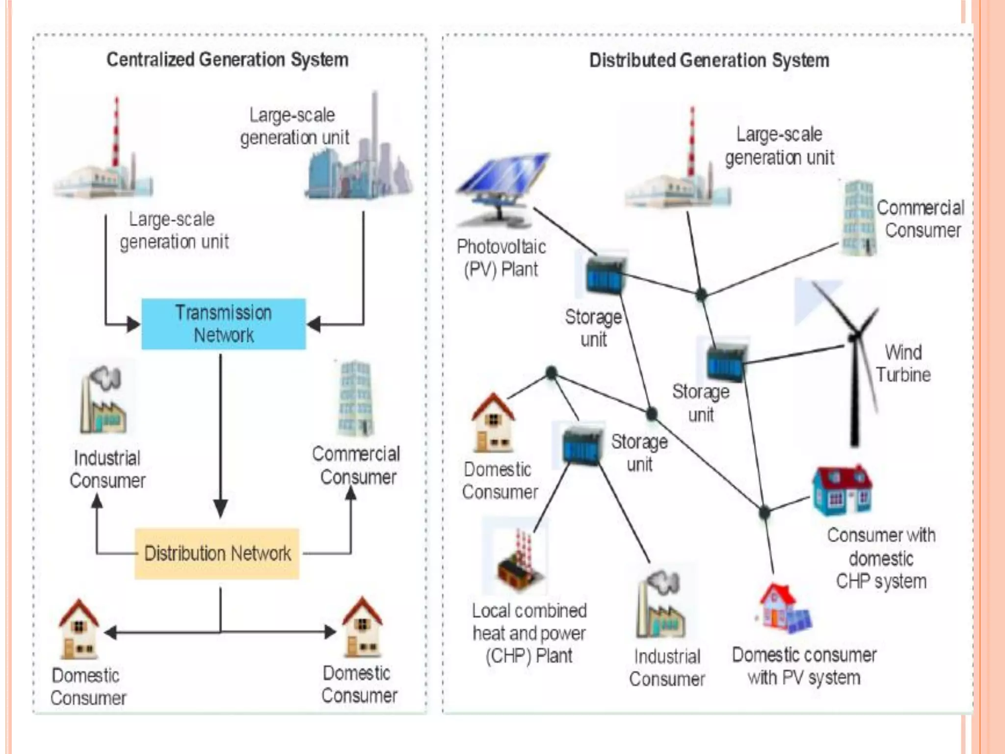
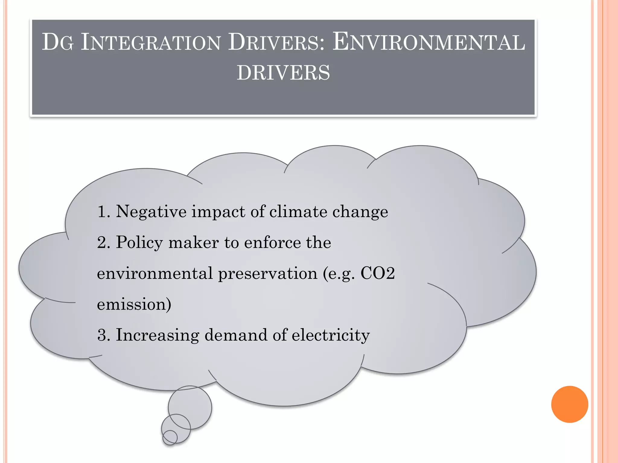
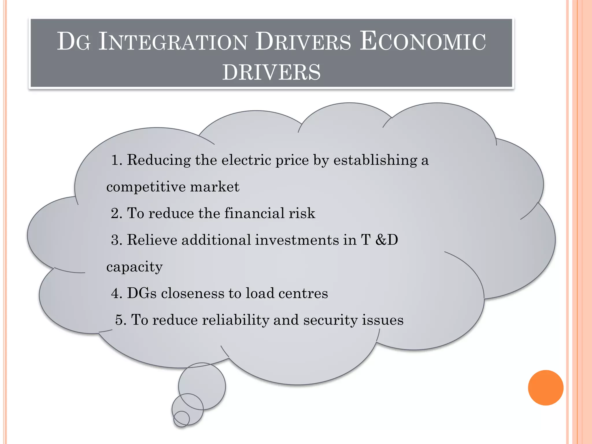
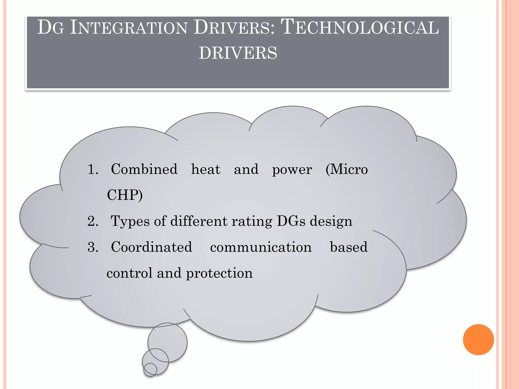
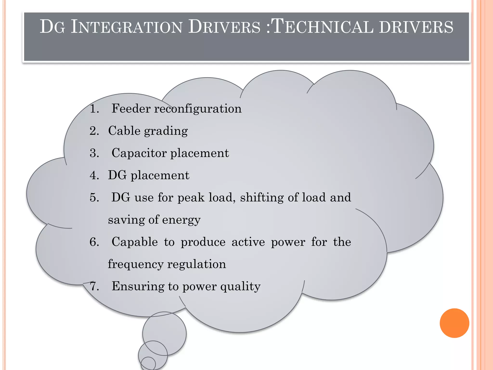
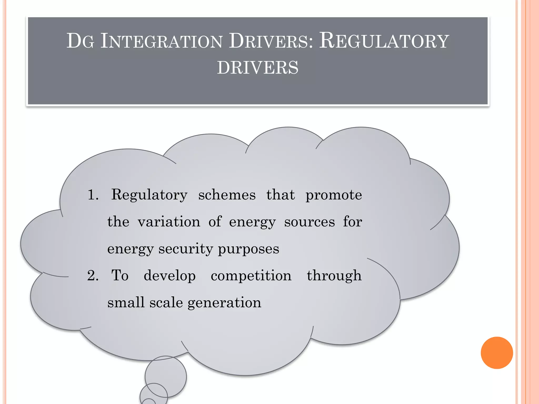
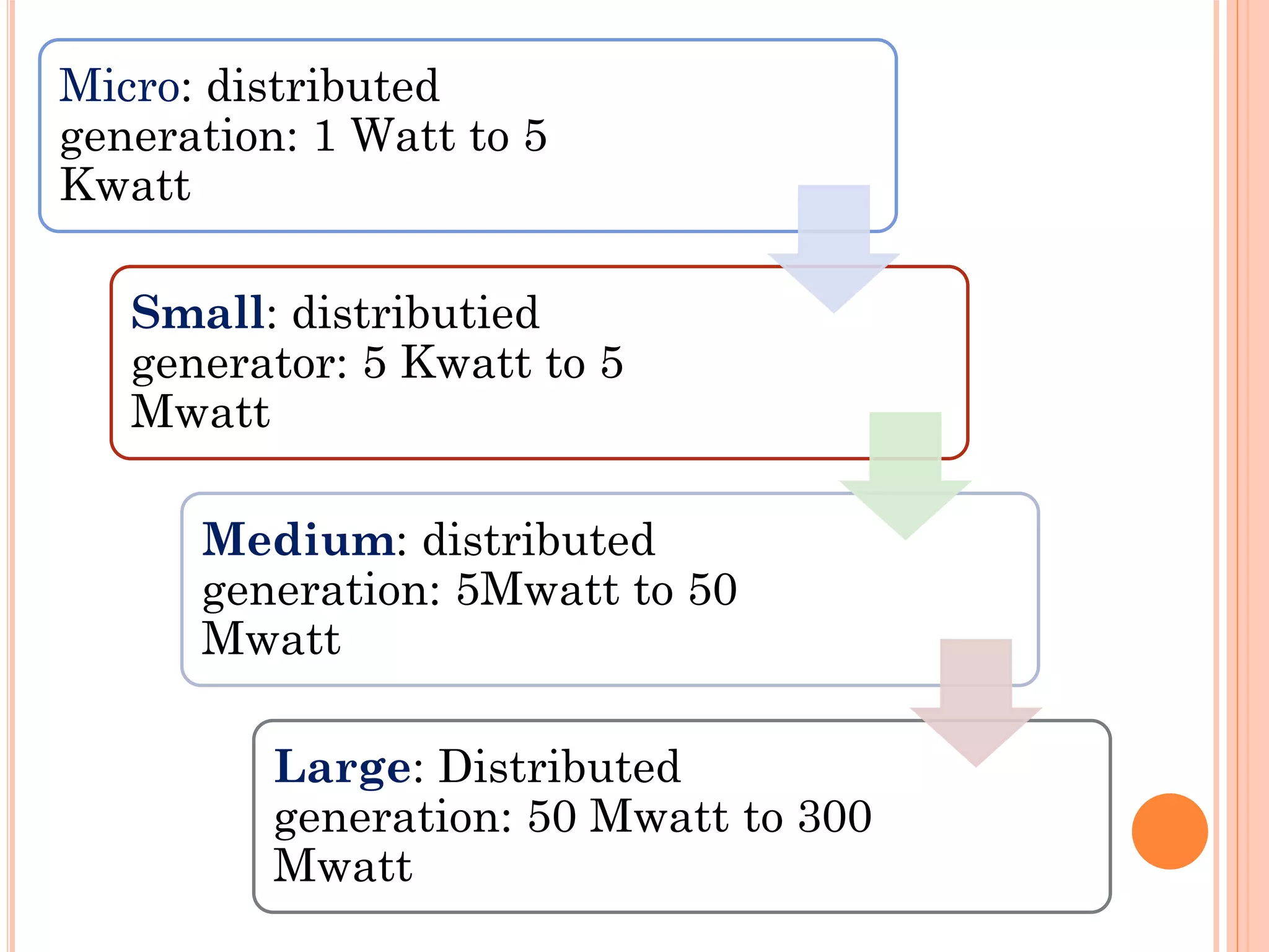
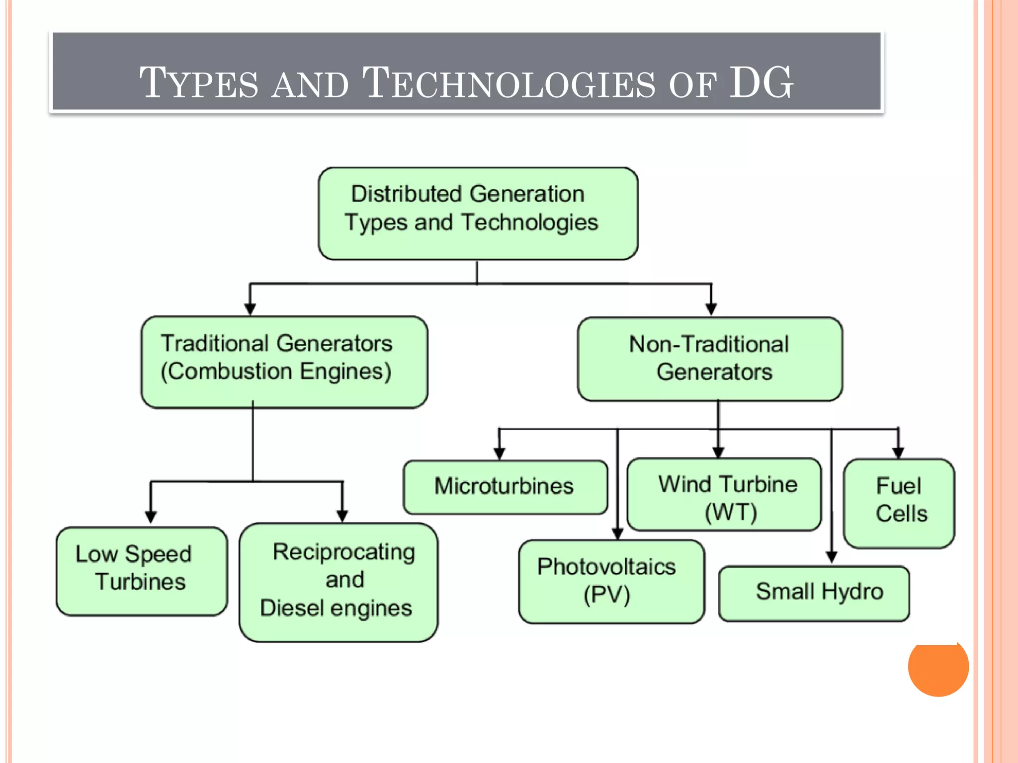
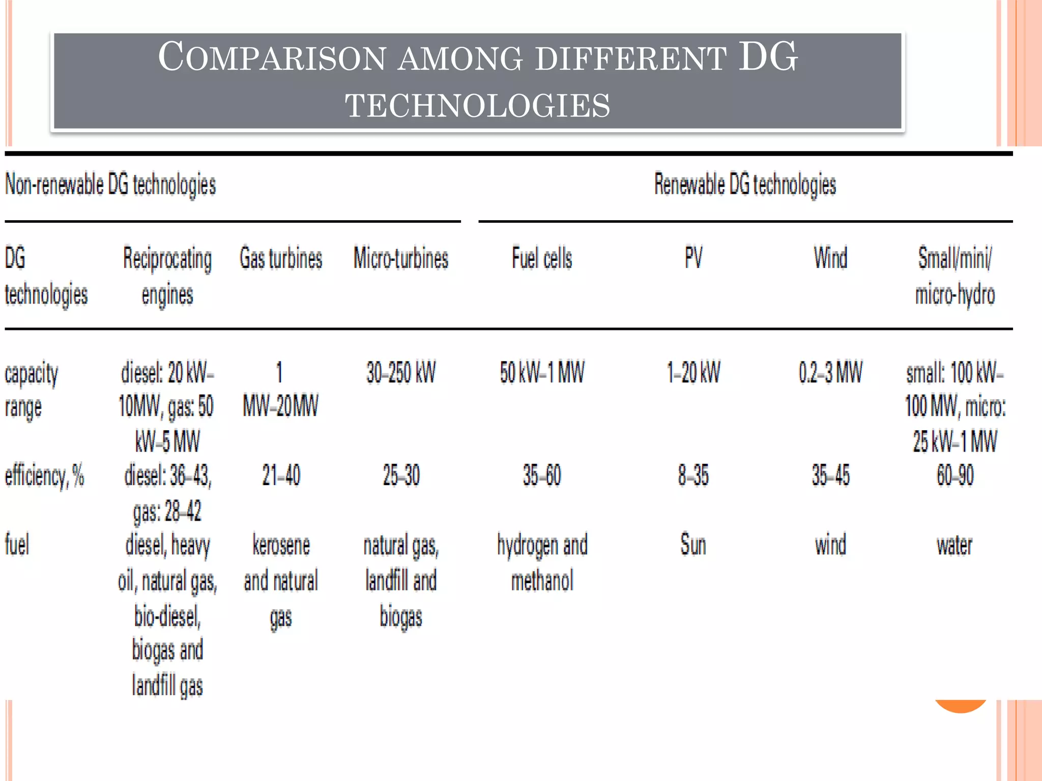
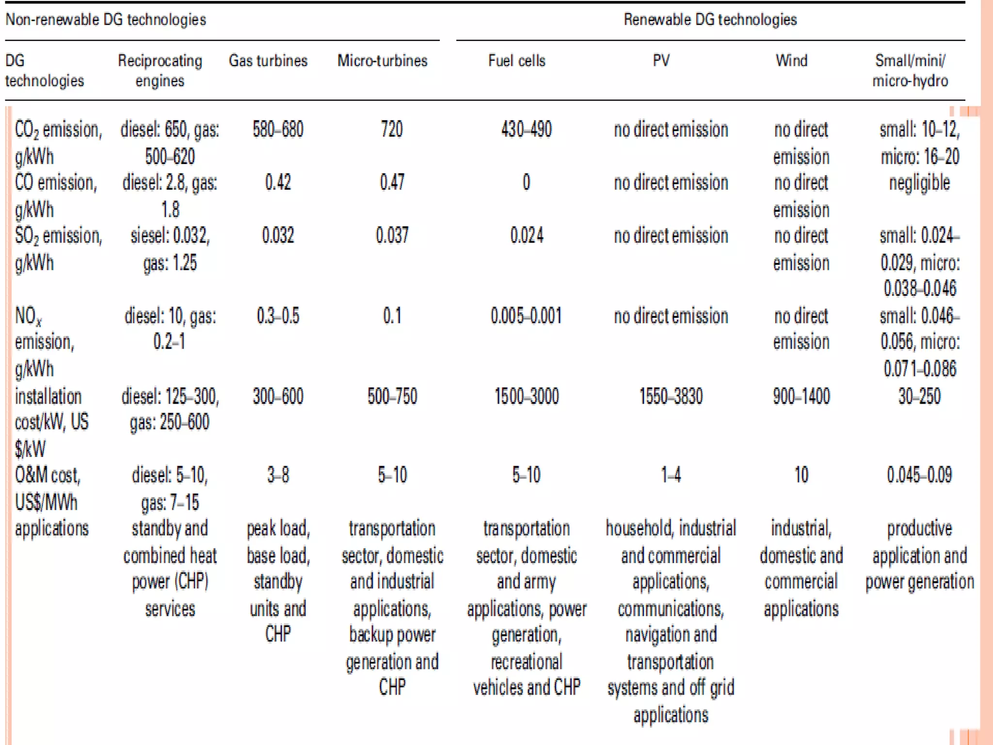
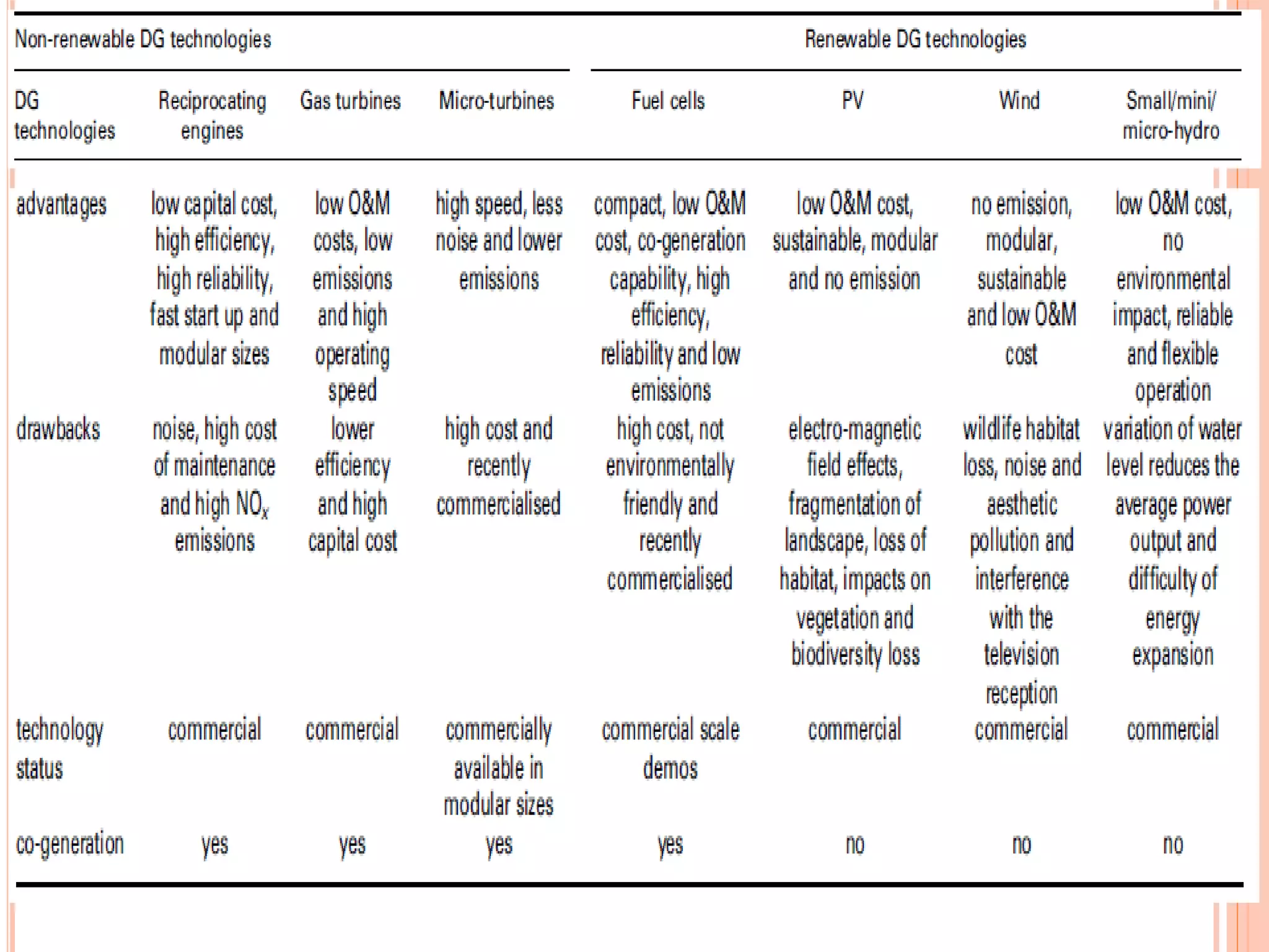
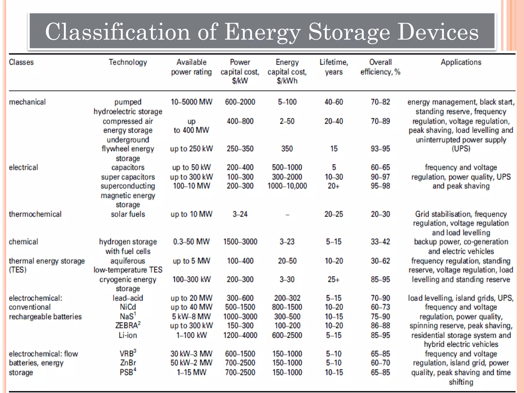
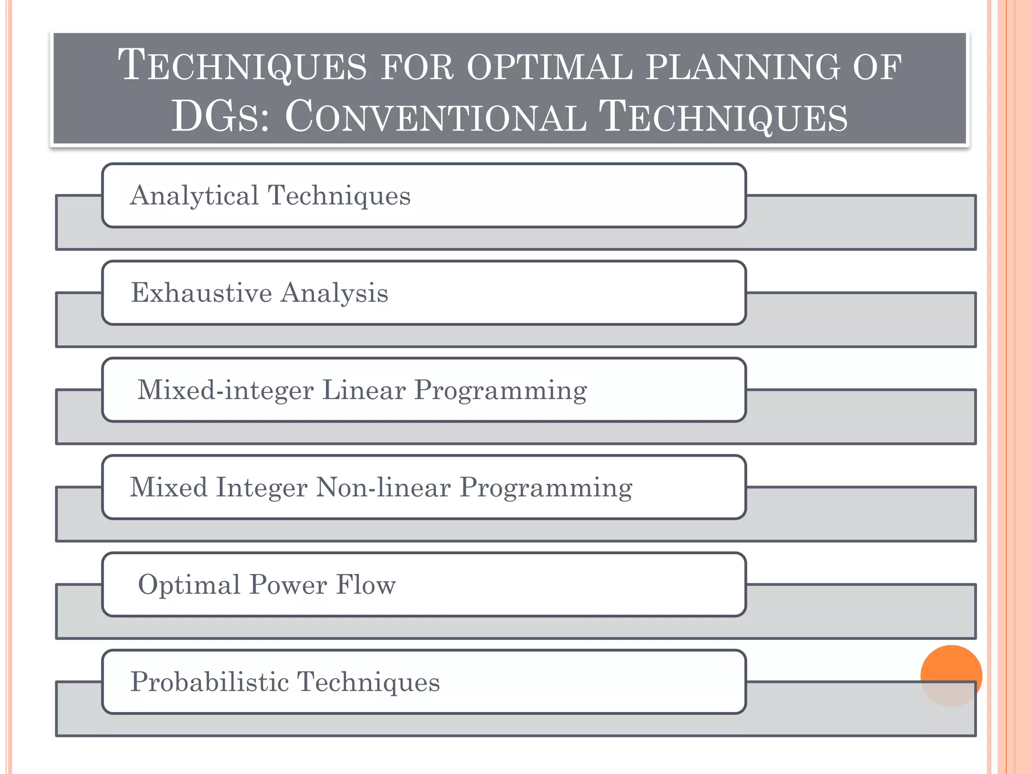
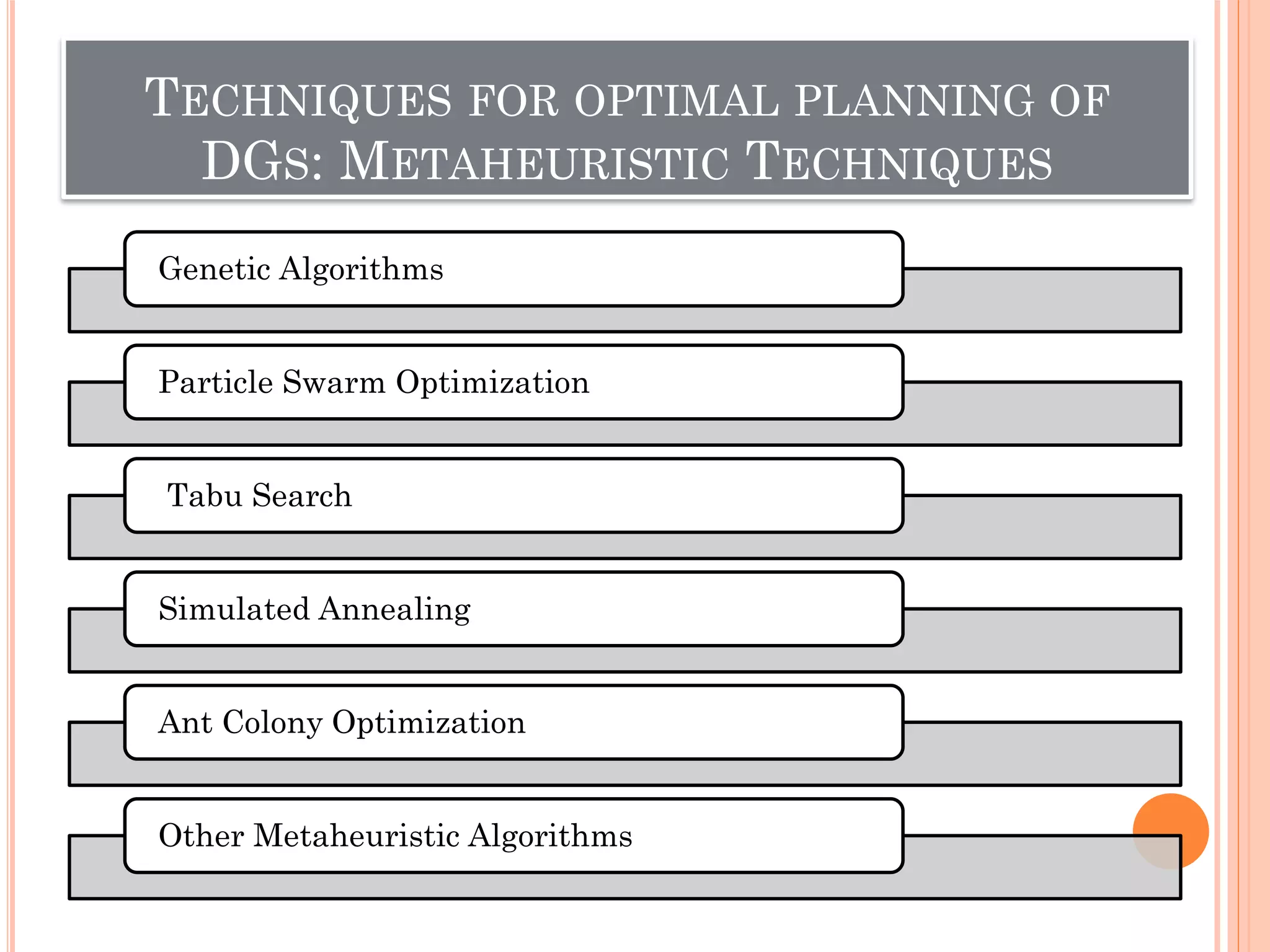
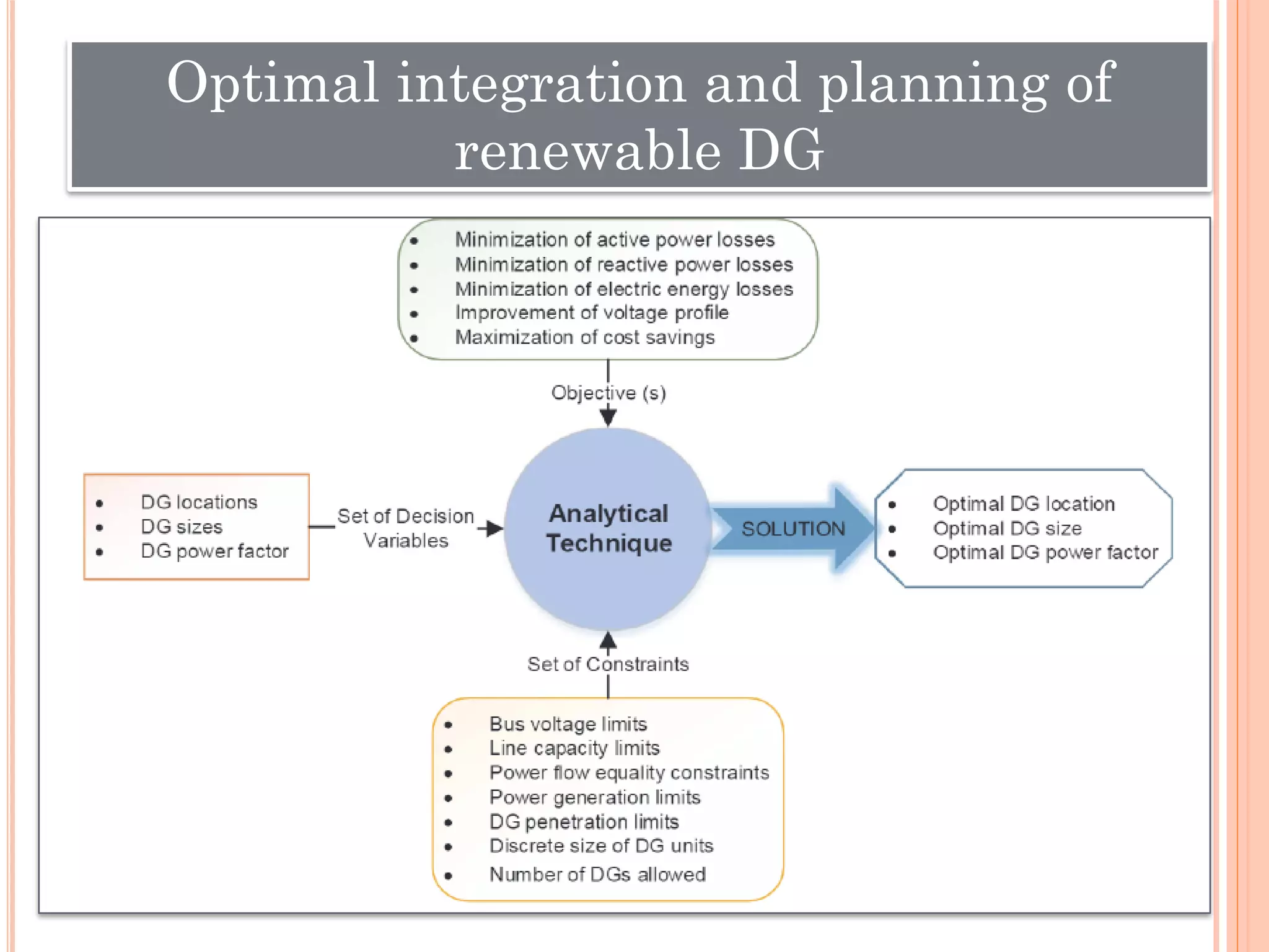
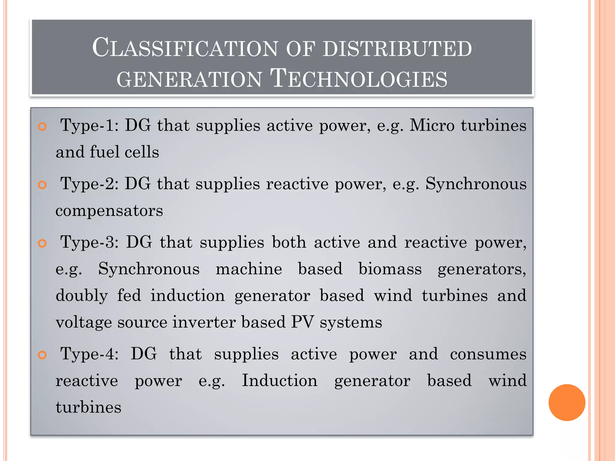
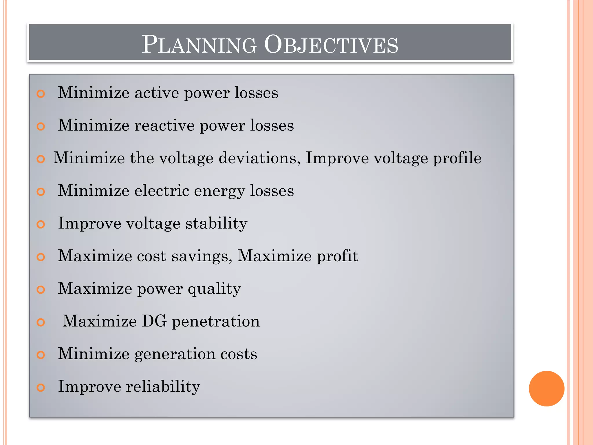
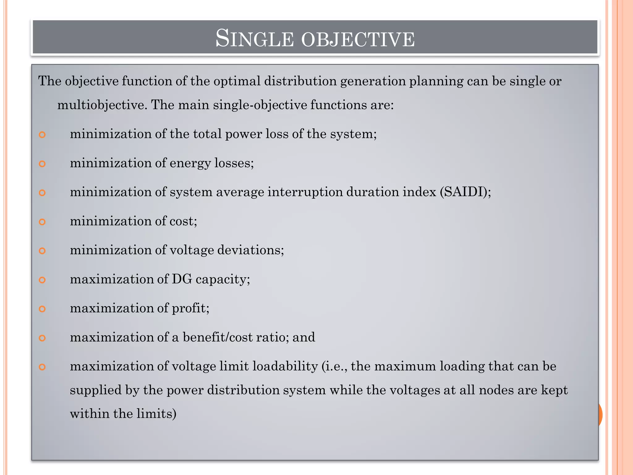
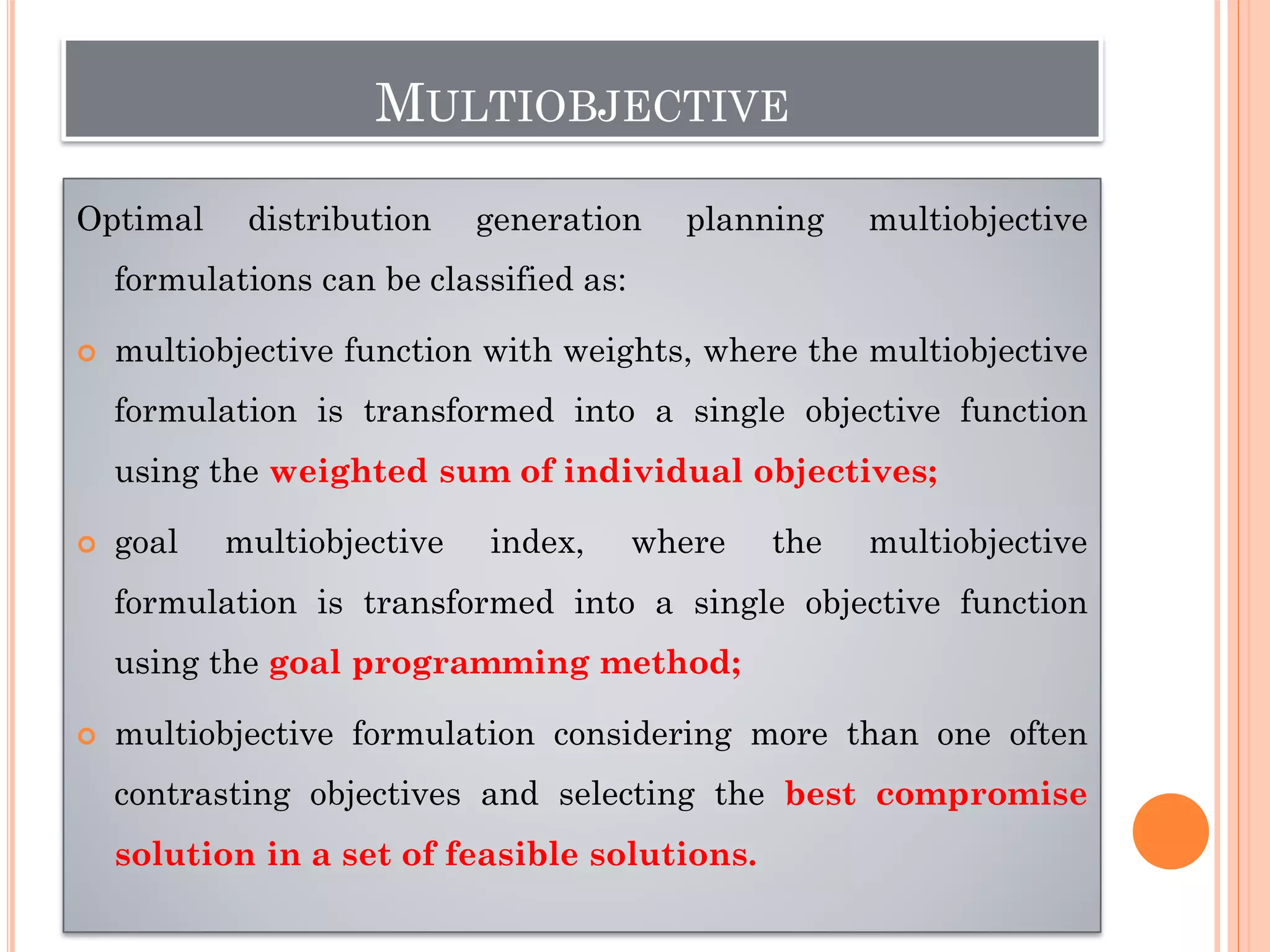
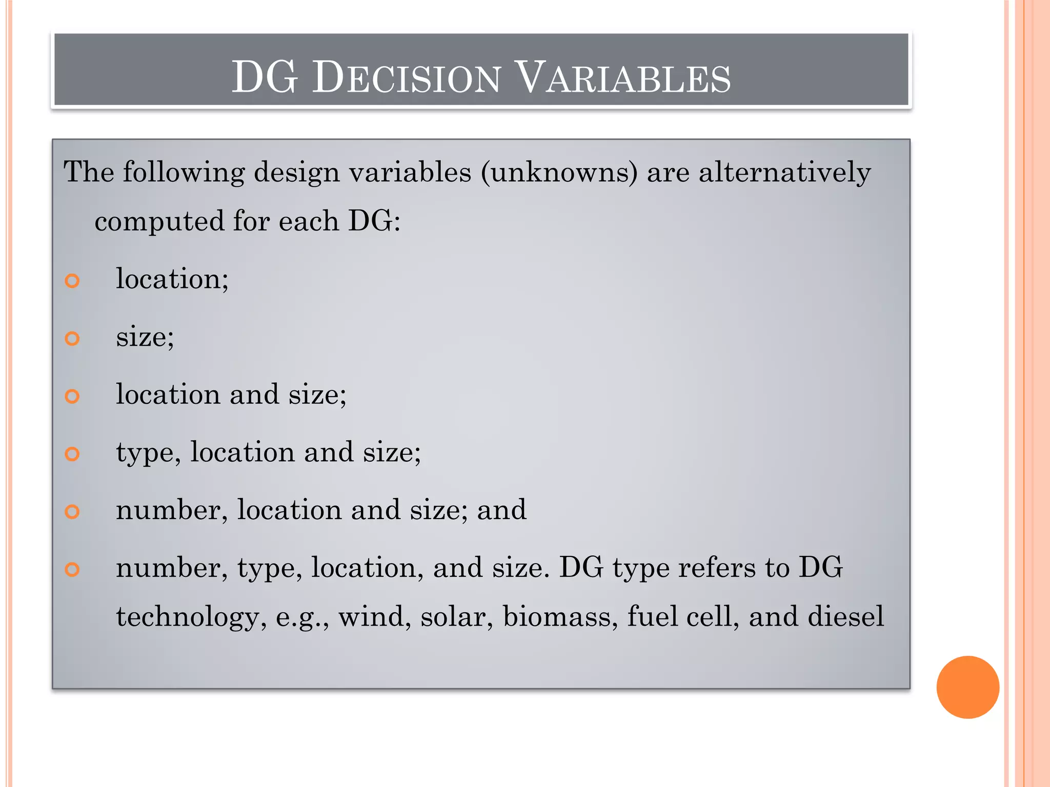
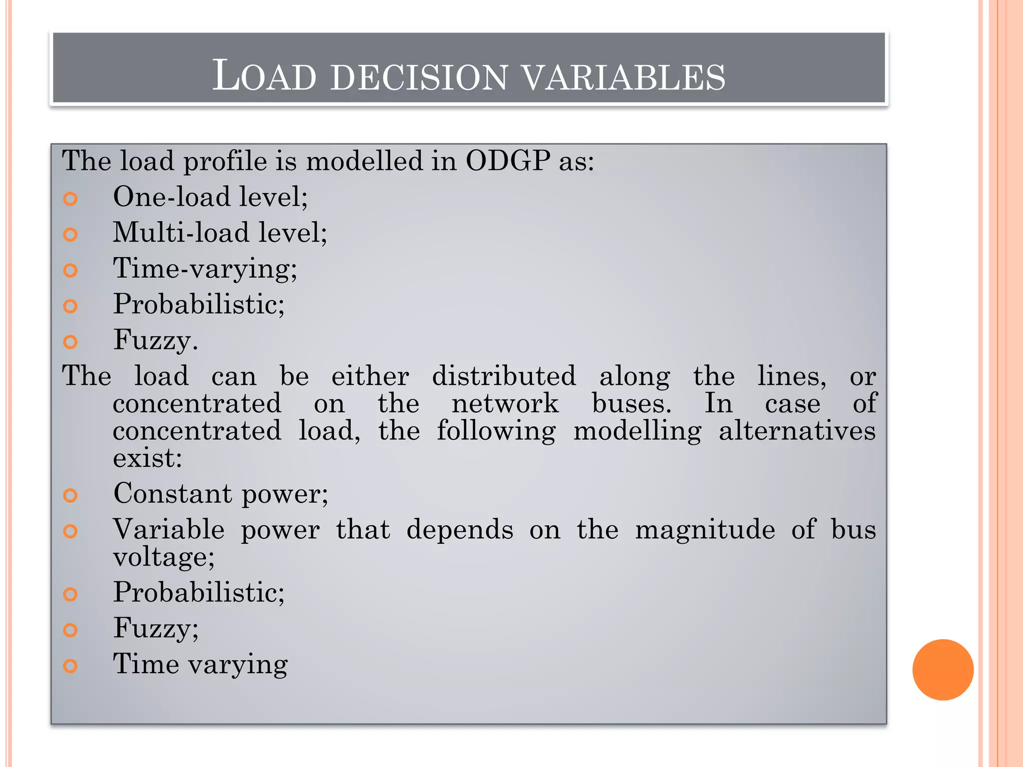
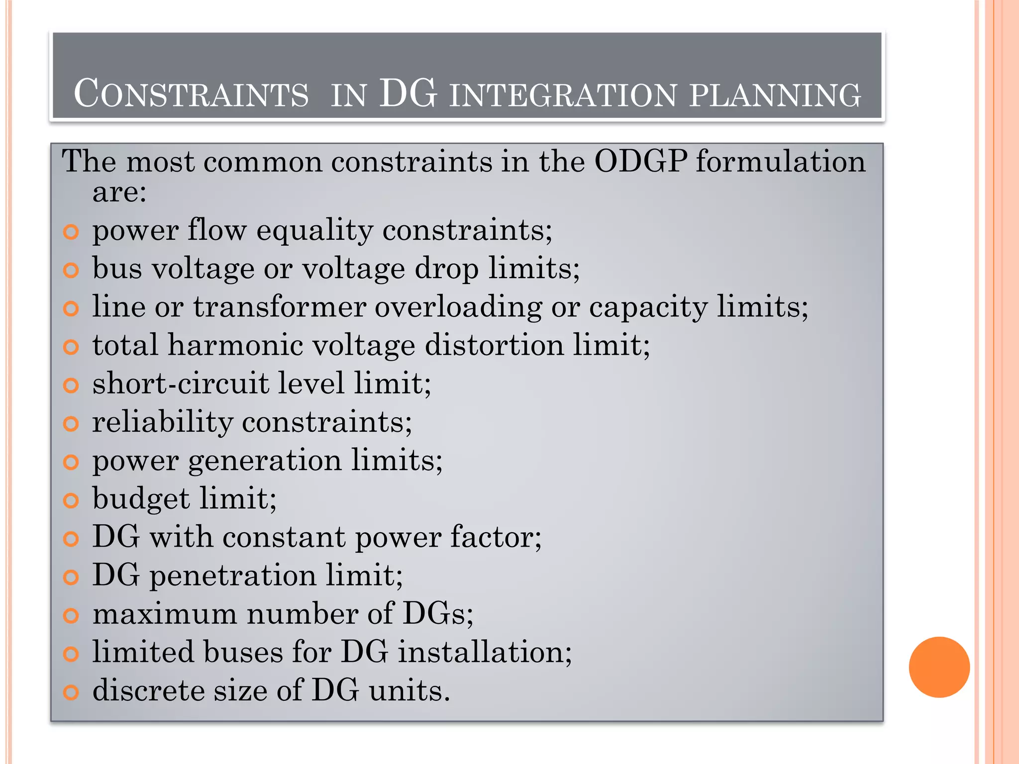
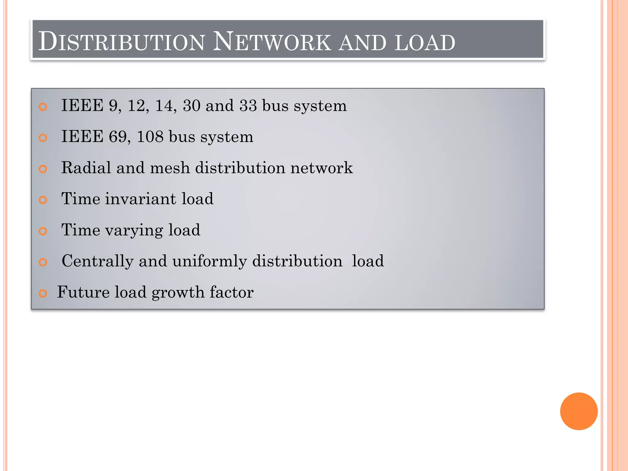
CLASS-3: INTEGRATION OF RENEWABLE
DISTRIBUTED GENERATORS IN
DISTRIBUTION SYSTEM
Course: Distribution Generation and Smart Grid
Prof. (Dr.) Pravat Kumar Rout
Department of EEE, ITER,
Siksha ‘O’ Anusandhan (Deemed to be University),
Bhubaneswar, Odisha, India
DG: DEFINITION
DG is defined as small generation units from a few
kilowatts (kW) up to 50 MW and/or energy storage
devices typically sited near customer loads or
distribution and sub-transmission substations as
distributed energy resources.
CONTINUE...
DG is defined as the generation of electricity from
facilities that are sufficiently smaller than central
generating plants so as to allow interconnection
at nearly any point in a power system
DG is defined as all generating units with a maximum
capacity of 50–100 MW that are usually connected to the
distribution network and that are neither centrally
planned nor dispatched.
CONTINUE....
DG is a type of generating plant that is tied to the
grid at the distribution level voltages to serve
a customer on site and at the same time to
provide support to a distributed network. The
technologies include reciprocating engines, turbines,
fuel cells and PV systems
Yearly installed capacity, share of capacity additions and
investigates of DG technologies worldwide
DG INTEGRATION DRIVERS
 Environmental drivers
 Economic drivers
 Technological drivers
 Technical drivers
 Regulatory drivers
DG INTEGRATION DRIVERS: ENVIRONMENTAL
DRIVERS
1. Negative impact of climate change
2. Policy maker to enforce the
environmental preservation (e.g. CO2
emission)
3. Increasing demand of electricity
DG INTEGRATION DRIVERS ECONOMIC
DRIVERS
1. Reducing the electric price by establishing a
competitive market
2. To reduce the financial risk
3. Relieve additional investments in T &D
capacity
4. DGs closeness to load centres
5. To reduce reliability and security issues
DG INTEGRATION DRIVERS: TECHNOLOGICAL
DRIVERS
1. Combined heat and power (Micro
CHP)
2. Types of different rating DGs design
3. Coordinated communication based
control and protection
DG INTEGRATION DRIVERS :TECHNICAL DRIVERS
1. Feeder reconfiguration
2. Cable grading
3. Capacitor placement
4. DG placement
5. DG use for peak load, shifting of load and
saving of energy
6. Capable to produce active power for the
frequency regulation
7. Ensuring to power quality
DG INTEGRATION DRIVERS: REGULATORY
DRIVERS
1. Regulatory schemes that promote
the variation of energy sources for
energy security purposes
2. To develop competition through
small scale generation
Micro: distributed
generation: 1 Watt to 5
Kwatt
Small: distributied
generator: 5 Kwatt to 5
Mwatt
Medium: distributed
generation: 5Mwatt to 50
Mwatt
Large: Distributed
generation: 50 Mwatt to 300
Mwatt
TYPES AND TECHNOLOGIES OF DG
COMPARISON AMONG DIFFERENT DG
TECHNOLOGIES
Classification of Energy Storage Devices
 Improved power system reliability
 Reduced capacity release
 Improved generation diversity
 Peak power reduction
BENEFITS OF DG: RELIABILITY
IMPROVEMENT
BENEFITS OF DG: VOLTAGE PROFILE/QUALITY
IMPROVEMENT
 Voltage quality improvement
 Voltage profile improvement
 Reduced voltage flicker
 Voltage support and better regulation
BENEFITS OF DG: LINE LOSS AND ENERGY
REDUCTION
 Reduced line losses
 Better control of reactive power
BENEFITS OF DG: SECURITY ENHANCEMENT
 Enhanced security of the critical loads
 Reduced security risks to the grid
 Improved power utilities security
 Reduced impacts of cyber-attacks
 Reduced vulnerability of terrorist attacks
BENEFITS OF DG: OPERATIONAL ADVANTAGES
 Provision of ancillary services
 Increased productivity
 Easy and quick to install
 Easy O & M
 Reduced reserved requirements
 Infrastructure resilience improvement
 Enhanced total efficiency
BENEFITS OF DG: ECONOMIC BENEFITS
 Reduced O&M costs
 Deferments of investment in infrastructures
 Reduction in losses associated costs
 No fuel cost with renewable DG
 Reduction in the right of way acquisition costs
 Reduction in the cost of installations
 Maintaining of constant running cost for longer
time period
 Reduction in the auxiliaries costs
BENEFITS OF DG: ENVIRONMENTAL
BENEFITS
 Reduction in land use effects
 Reduction in health costs with renewable DG
 Environment friendly with renewable DG
 Reduction in GHG (Green House Gases) emission pollutants
with renewable DG
TECHNIQUES FOR OPTIMAL PLANNING OF
DGS: CONVENTIONAL TECHNIQUES
Analytical Techniques
Exhaustive Analysis
Mixed-integer Linear Programming
Mixed Integer Non-linear Programming
Optimal Power Flow
Probabilistic Techniques
TECHNIQUES FOR OPTIMAL PLANNING OF
DGS: METAHEURISTIC TECHNIQUES
Genetic Algorithms
Particle Swarm Optimization
Tabu Search
Simulated Annealing
Ant Colony Optimization
Other Metaheuristic Algorithms
Optimal integration and planning of
renewable DG
CLASSIFICATION OF DISTRIBUTED
GENERATION TECHNOLOGIES
 Type-1: DG that supplies active power, e.g. Micro turbines
and fuel cells
 Type-2: DG that supplies reactive power, e.g. Synchronous
compensators
 Type-3: DG that supplies both active and reactive power,
e.g. Synchronous machine based biomass generators,
doubly fed induction generator based wind turbines and
voltage source inverter based PV systems
 Type-4: DG that supplies active power and consumes
reactive power e.g. Induction generator based wind
turbines
PLANNING OBJECTIVES
 Minimize active power losses
 Minimize reactive power losses
 Minimize the voltage deviations, Improve voltage profile
 Minimize electric energy losses
 Improve voltage stability
 Maximize cost savings, Maximize profit
 Maximize power quality
 Maximize DG penetration
 Minimize generation costs
 Improve reliability
SINGLE OBJECTIVE
The objective function of the optimal distribution generation planning can be single or
multiobjective. The main single-objective functions are:
 minimization of the total power loss of the system;
 minimization of energy losses;
 minimization of system average interruption duration index (SAIDI);
 minimization of cost;
 minimization of voltage deviations;
 maximization of DG capacity;
 maximization of profit;
 maximization of a benefit/cost ratio; and
 maximization of voltage limit loadability (i.e., the maximum loading that can be
supplied by the power distribution system while the voltages at all nodes are kept
within the limits)
MULTIOBJECTIVE
Optimal distribution generation planning multiobjective
formulations can be classified as:
 multiobjective function with weights, where the multiobjective
formulation is transformed into a single objective function
using the weighted sum of individual objectives;
 goal multiobjective index, where the multiobjective
formulation is transformed into a single objective function
using the goal programming method;
 multiobjective formulation considering more than one often
contrasting objectives and selecting the best compromise
solution in a set of feasible solutions.
DG DECISION VARIABLES
The following design variables (unknowns) are alternatively
computed for each DG:
 location;
 size;
 location and size;
 type, location and size;
 number, location and size; and
 number, type, location, and size. DG type refers to DG
technology, e.g., wind, solar, biomass, fuel cell, and diesel
LOAD DECISION VARIABLES
The load profile is modelled in ODGP as:
 One-load level;
 Multi-load level;
 Time-varying;
 Probabilistic;
 Fuzzy.
The load can be either distributed along the lines, or
concentrated on the network buses. In case of
concentrated load, the following modelling alternatives
exist:
 Constant power;
 Variable power that depends on the magnitude of bus
voltage;
 Probabilistic;
 Fuzzy;
 Time varying
CONSTRAINTS IN DG INTEGRATION PLANNING
The most common constraints in the ODGP formulation
are:
 power flow equality constraints;
 bus voltage or voltage drop limits;
 line or transformer overloading or capacity limits;
 total harmonic voltage distortion limit;
 short-circuit level limit;
 reliability constraints;
 power generation limits;
 budget limit;
 DG with constant power factor;
 DG penetration limit;
 maximum number of DGs;
 limited buses for DG installation;
 discrete size of DG units.
DISTRIBUTION NETWORK AND LOAD
 IEEE 9, 12, 14, 30 and 33 bus system
 IEEE 69, 108 bus system
 Radial and mesh distribution network
 Time invariant load
 Time varying load
 Centrally and uniformly distribution load
 Future load growth factor
REFERENCES
 Ehsan, A., & Yang, Q. (2018). Optimal integration and planning of
renewable distributed generation in the power distribution networks:
A review of analytical techniques. Applied Energy, 210, 44-59.
 Abookazemi, K., Hassan, M. Y., & Majid, M. S. (2010, December). A
review on optimal placement methods of distribution generation
sources. In 2010 IEEE International Conference on Power and
Energy (pp. 712-716). IEEE.
 El-Khattam, W., & Salama, M. M. (2004). Distributed generation
technologies, definitions and benefits. Electric power systems
research, 71(2), 119-128.
 Adefarati, T., & Bansal, R. C. (2016). Integration of renewable
distributed generators into the distribution system: a review. IET
Renewable Power Generation, 10(7), 873-884.
QUESTIONS
 What are the major drivers responsible for the DG
integration in distribution and transmission level.
 What are the major objectives to be focussed at the time
distribution network planning.
Integration of Renewable Distributed Generators in Distribution System

Integration of Renewable Distributed Generators in Distribution System

  • 1.
    CLASS-3: INTEGRATION OFRENEWABLE DISTRIBUTED GENERATORS IN DISTRIBUTION SYSTEM Course: Distribution Generation and Smart Grid Prof. (Dr.) Pravat Kumar Rout Department of EEE, ITER, Siksha ‘O’ Anusandhan (Deemed to be University), Bhubaneswar, Odisha, India
  • 2.
    DG: DEFINITION DG isdefined as small generation units from a few kilowatts (kW) up to 50 MW and/or energy storage devices typically sited near customer loads or distribution and sub-transmission substations as distributed energy resources.
  • 3.
    CONTINUE... DG is definedas the generation of electricity from facilities that are sufficiently smaller than central generating plants so as to allow interconnection at nearly any point in a power system DG is defined as all generating units with a maximum capacity of 50–100 MW that are usually connected to the distribution network and that are neither centrally planned nor dispatched.
  • 4.
    CONTINUE.... DG is atype of generating plant that is tied to the grid at the distribution level voltages to serve a customer on site and at the same time to provide support to a distributed network. The technologies include reciprocating engines, turbines, fuel cells and PV systems
  • 5.
    Yearly installed capacity,share of capacity additions and investigates of DG technologies worldwide
  • 7.
    DG INTEGRATION DRIVERS Environmental drivers  Economic drivers  Technological drivers  Technical drivers  Regulatory drivers
  • 8.
    DG INTEGRATION DRIVERS:ENVIRONMENTAL DRIVERS 1. Negative impact of climate change 2. Policy maker to enforce the environmental preservation (e.g. CO2 emission) 3. Increasing demand of electricity
  • 9.
    DG INTEGRATION DRIVERSECONOMIC DRIVERS 1. Reducing the electric price by establishing a competitive market 2. To reduce the financial risk 3. Relieve additional investments in T &D capacity 4. DGs closeness to load centres 5. To reduce reliability and security issues
  • 10.
    DG INTEGRATION DRIVERS:TECHNOLOGICAL DRIVERS 1. Combined heat and power (Micro CHP) 2. Types of different rating DGs design 3. Coordinated communication based control and protection
  • 11.
    DG INTEGRATION DRIVERS:TECHNICAL DRIVERS 1. Feeder reconfiguration 2. Cable grading 3. Capacitor placement 4. DG placement 5. DG use for peak load, shifting of load and saving of energy 6. Capable to produce active power for the frequency regulation 7. Ensuring to power quality
  • 12.
    DG INTEGRATION DRIVERS:REGULATORY DRIVERS 1. Regulatory schemes that promote the variation of energy sources for energy security purposes 2. To develop competition through small scale generation
  • 13.
    Micro: distributed generation: 1Watt to 5 Kwatt Small: distributied generator: 5 Kwatt to 5 Mwatt Medium: distributed generation: 5Mwatt to 50 Mwatt Large: Distributed generation: 50 Mwatt to 300 Mwatt
  • 14.
  • 15.
  • 18.
    Classification of EnergyStorage Devices
  • 19.
     Improved powersystem reliability  Reduced capacity release  Improved generation diversity  Peak power reduction BENEFITS OF DG: RELIABILITY IMPROVEMENT
  • 20.
    BENEFITS OF DG:VOLTAGE PROFILE/QUALITY IMPROVEMENT  Voltage quality improvement  Voltage profile improvement  Reduced voltage flicker  Voltage support and better regulation
  • 21.
    BENEFITS OF DG:LINE LOSS AND ENERGY REDUCTION  Reduced line losses  Better control of reactive power
  • 22.
    BENEFITS OF DG:SECURITY ENHANCEMENT  Enhanced security of the critical loads  Reduced security risks to the grid  Improved power utilities security  Reduced impacts of cyber-attacks  Reduced vulnerability of terrorist attacks
  • 23.
    BENEFITS OF DG:OPERATIONAL ADVANTAGES  Provision of ancillary services  Increased productivity  Easy and quick to install  Easy O & M  Reduced reserved requirements  Infrastructure resilience improvement  Enhanced total efficiency
  • 24.
    BENEFITS OF DG:ECONOMIC BENEFITS  Reduced O&M costs  Deferments of investment in infrastructures  Reduction in losses associated costs  No fuel cost with renewable DG  Reduction in the right of way acquisition costs  Reduction in the cost of installations  Maintaining of constant running cost for longer time period  Reduction in the auxiliaries costs
  • 25.
    BENEFITS OF DG:ENVIRONMENTAL BENEFITS  Reduction in land use effects  Reduction in health costs with renewable DG  Environment friendly with renewable DG  Reduction in GHG (Green House Gases) emission pollutants with renewable DG
  • 26.
    TECHNIQUES FOR OPTIMALPLANNING OF DGS: CONVENTIONAL TECHNIQUES Analytical Techniques Exhaustive Analysis Mixed-integer Linear Programming Mixed Integer Non-linear Programming Optimal Power Flow Probabilistic Techniques
  • 27.
    TECHNIQUES FOR OPTIMALPLANNING OF DGS: METAHEURISTIC TECHNIQUES Genetic Algorithms Particle Swarm Optimization Tabu Search Simulated Annealing Ant Colony Optimization Other Metaheuristic Algorithms
  • 28.
    Optimal integration andplanning of renewable DG
  • 29.
    CLASSIFICATION OF DISTRIBUTED GENERATIONTECHNOLOGIES  Type-1: DG that supplies active power, e.g. Micro turbines and fuel cells  Type-2: DG that supplies reactive power, e.g. Synchronous compensators  Type-3: DG that supplies both active and reactive power, e.g. Synchronous machine based biomass generators, doubly fed induction generator based wind turbines and voltage source inverter based PV systems  Type-4: DG that supplies active power and consumes reactive power e.g. Induction generator based wind turbines
  • 30.
    PLANNING OBJECTIVES  Minimizeactive power losses  Minimize reactive power losses  Minimize the voltage deviations, Improve voltage profile  Minimize electric energy losses  Improve voltage stability  Maximize cost savings, Maximize profit  Maximize power quality  Maximize DG penetration  Minimize generation costs  Improve reliability
  • 31.
    SINGLE OBJECTIVE The objectivefunction of the optimal distribution generation planning can be single or multiobjective. The main single-objective functions are:  minimization of the total power loss of the system;  minimization of energy losses;  minimization of system average interruption duration index (SAIDI);  minimization of cost;  minimization of voltage deviations;  maximization of DG capacity;  maximization of profit;  maximization of a benefit/cost ratio; and  maximization of voltage limit loadability (i.e., the maximum loading that can be supplied by the power distribution system while the voltages at all nodes are kept within the limits)
  • 32.
    MULTIOBJECTIVE Optimal distribution generationplanning multiobjective formulations can be classified as:  multiobjective function with weights, where the multiobjective formulation is transformed into a single objective function using the weighted sum of individual objectives;  goal multiobjective index, where the multiobjective formulation is transformed into a single objective function using the goal programming method;  multiobjective formulation considering more than one often contrasting objectives and selecting the best compromise solution in a set of feasible solutions.
  • 33.
    DG DECISION VARIABLES Thefollowing design variables (unknowns) are alternatively computed for each DG:  location;  size;  location and size;  type, location and size;  number, location and size; and  number, type, location, and size. DG type refers to DG technology, e.g., wind, solar, biomass, fuel cell, and diesel
  • 34.
    LOAD DECISION VARIABLES Theload profile is modelled in ODGP as:  One-load level;  Multi-load level;  Time-varying;  Probabilistic;  Fuzzy. The load can be either distributed along the lines, or concentrated on the network buses. In case of concentrated load, the following modelling alternatives exist:  Constant power;  Variable power that depends on the magnitude of bus voltage;  Probabilistic;  Fuzzy;  Time varying
  • 35.
    CONSTRAINTS IN DGINTEGRATION PLANNING The most common constraints in the ODGP formulation are:  power flow equality constraints;  bus voltage or voltage drop limits;  line or transformer overloading or capacity limits;  total harmonic voltage distortion limit;  short-circuit level limit;  reliability constraints;  power generation limits;  budget limit;  DG with constant power factor;  DG penetration limit;  maximum number of DGs;  limited buses for DG installation;  discrete size of DG units.
  • 36.
    DISTRIBUTION NETWORK ANDLOAD  IEEE 9, 12, 14, 30 and 33 bus system  IEEE 69, 108 bus system  Radial and mesh distribution network  Time invariant load  Time varying load  Centrally and uniformly distribution load  Future load growth factor
  • 37.
    REFERENCES  Ehsan, A.,& Yang, Q. (2018). Optimal integration and planning of renewable distributed generation in the power distribution networks: A review of analytical techniques. Applied Energy, 210, 44-59.  Abookazemi, K., Hassan, M. Y., & Majid, M. S. (2010, December). A review on optimal placement methods of distribution generation sources. In 2010 IEEE International Conference on Power and Energy (pp. 712-716). IEEE.  El-Khattam, W., & Salama, M. M. (2004). Distributed generation technologies, definitions and benefits. Electric power systems research, 71(2), 119-128.  Adefarati, T., & Bansal, R. C. (2016). Integration of renewable distributed generators into the distribution system: a review. IET Renewable Power Generation, 10(7), 873-884.
  • 38.
    QUESTIONS  What arethe major drivers responsible for the DG integration in distribution and transmission level.  What are the major objectives to be focussed at the time distribution network planning.