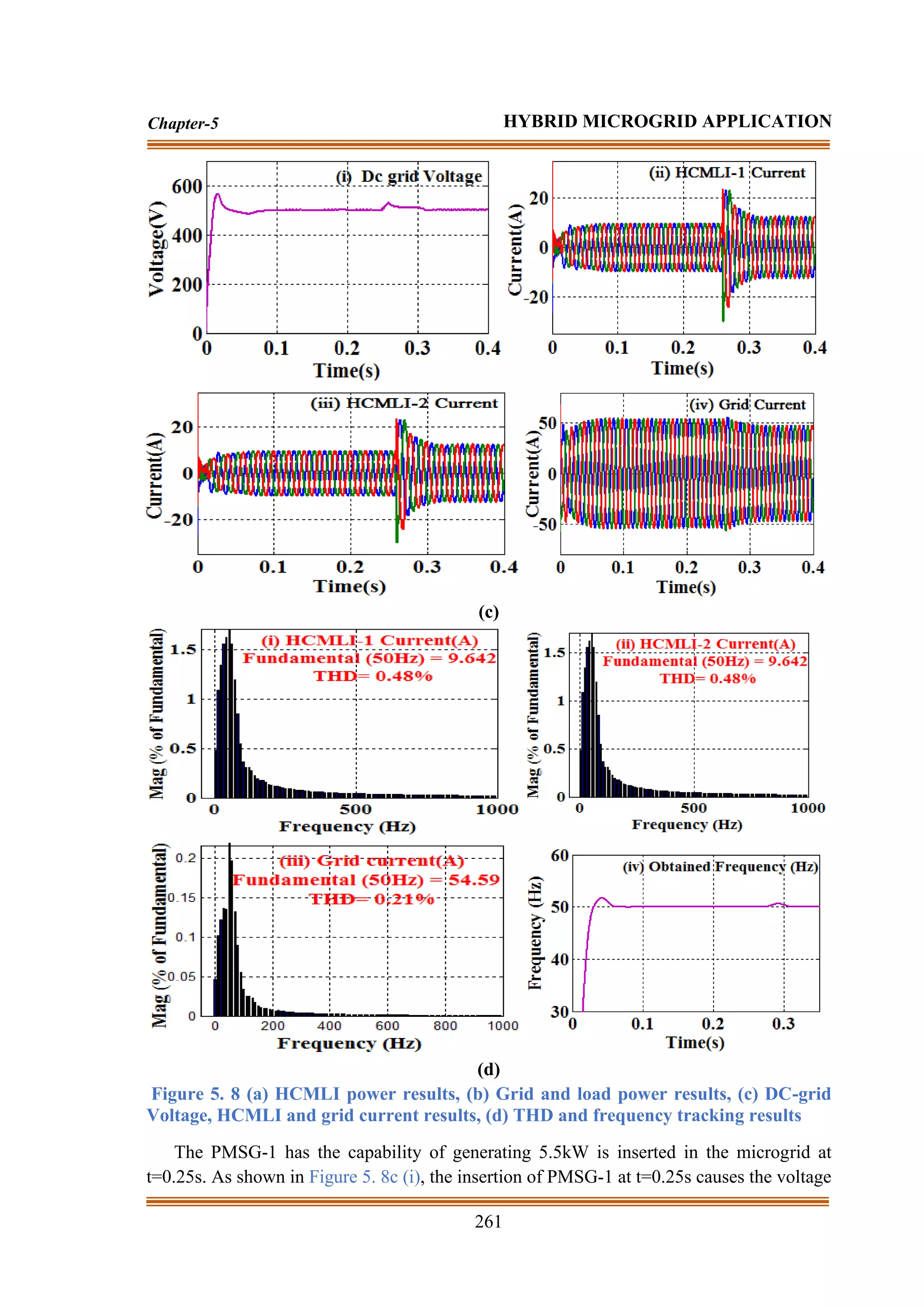
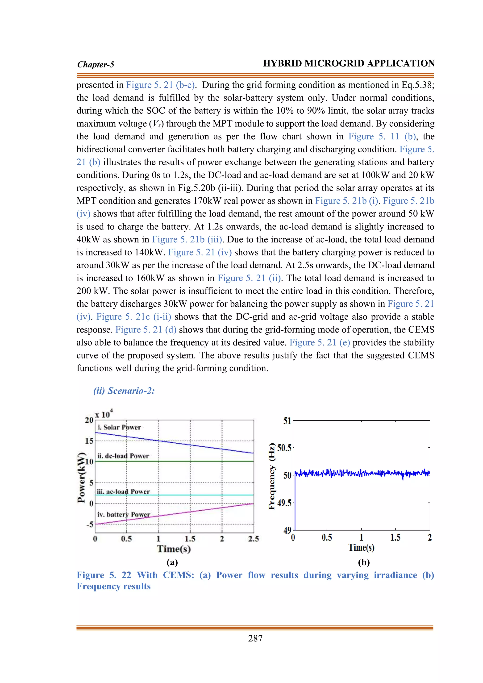
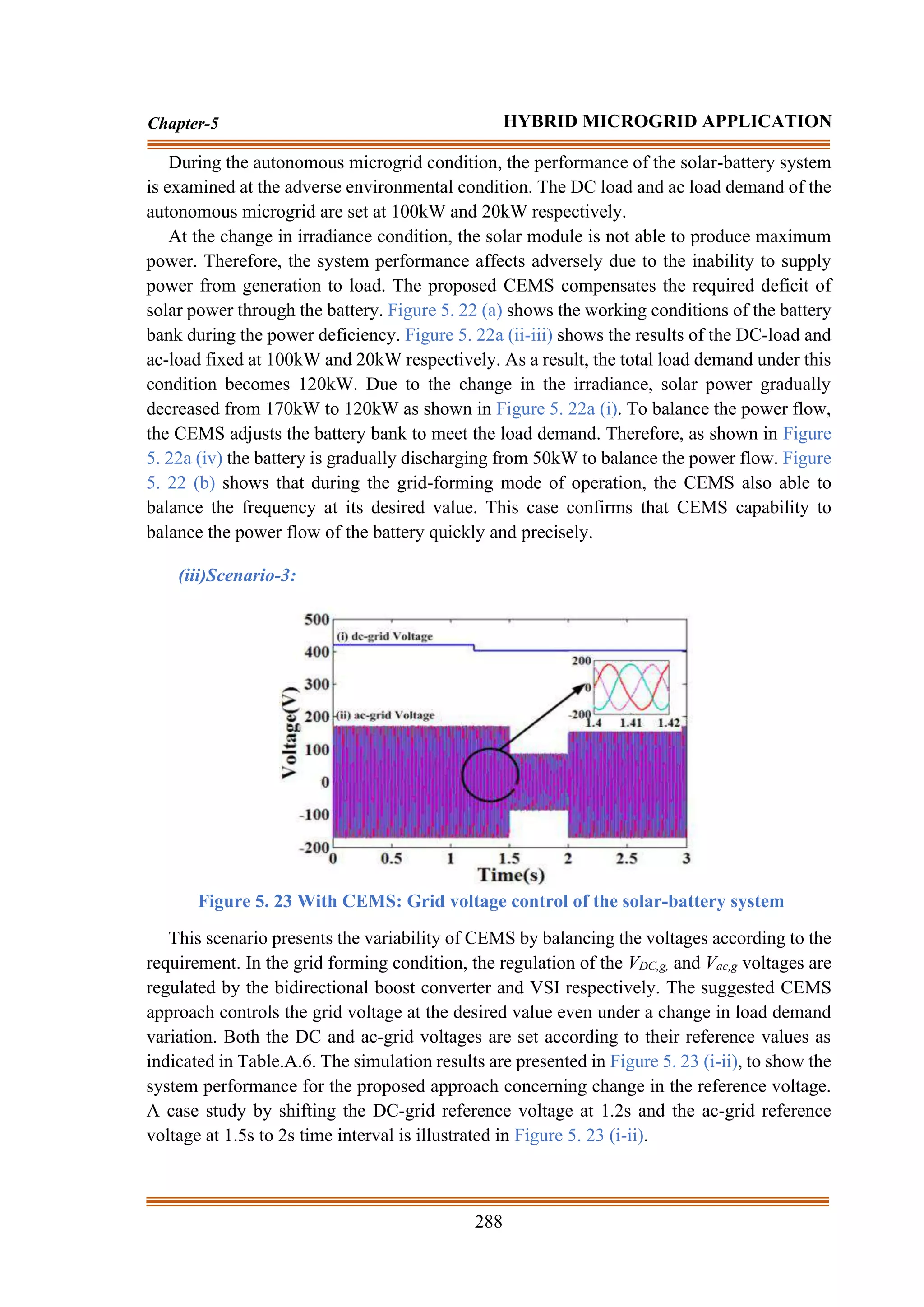
The document discusses hybrid microgrid applications involving renewable energy sources like solar and wind. It notes that the variable output from these sources can cause power quality issues in hybrid microgrids. Two studies are proposed to address this: 1) A robust control approach is proposed to integrate a DC-grid based wind energy conversion system to improve reliability. 2) A novel centralized energy management approach is suggested to suppress voltage variations and improve power quality, using a battery energy storage system. The document also reviews various multilevel inverter topologies used for renewable energy integration and highlights the need for improved topologies to balance capacitor voltages and minimize harmonics.


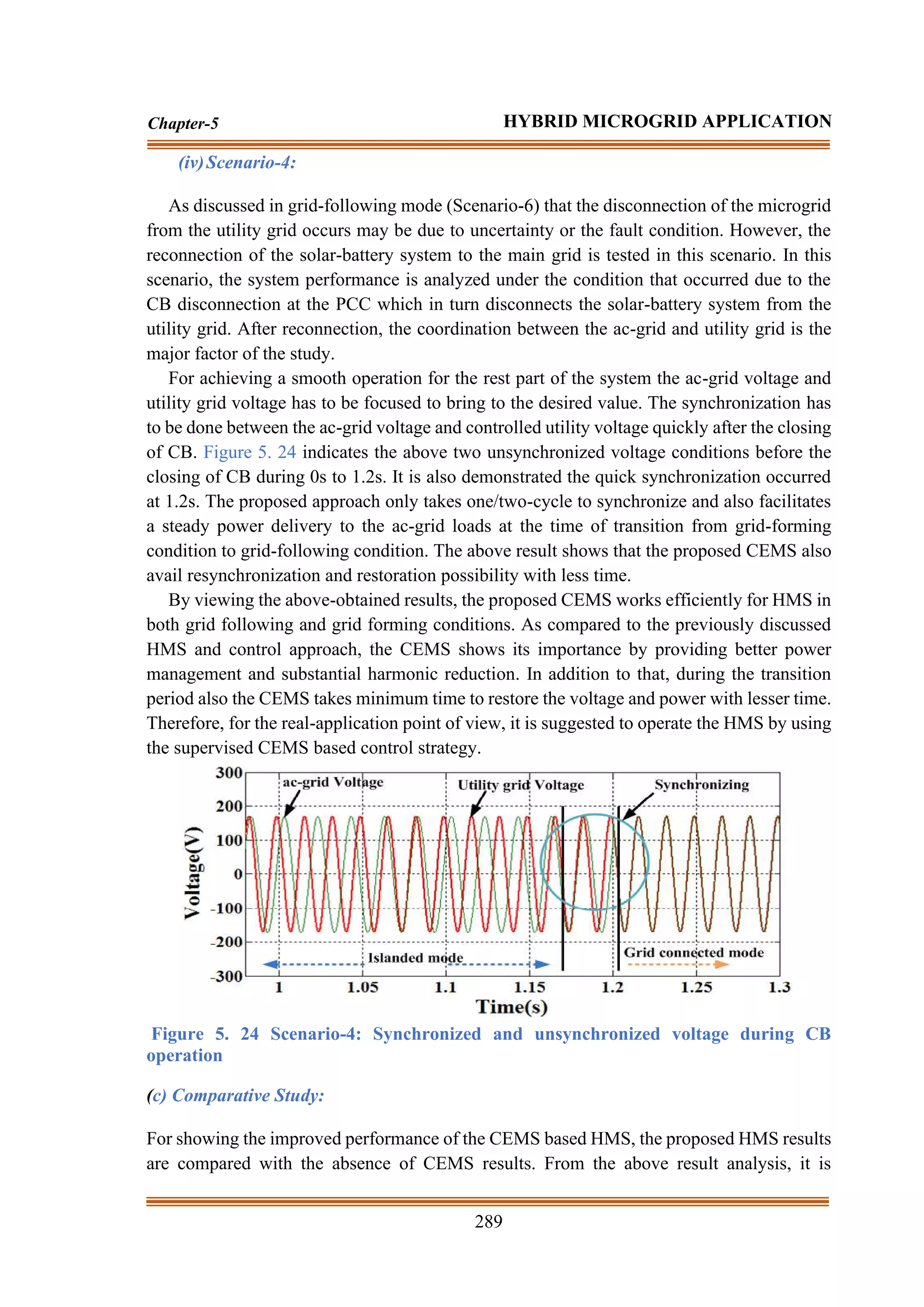
![Chapter-5
HYBRID MICROGRID APPLICATION
5.1 Introduction
High energy demand and increased population conditions motivate many electrical power
experts to get different sustainable solutions for an appropriate amount of energy production
by reducing the dependency on traditional energy production [154]. To regulate the PQ and
power reliability, solar array and wind energy-based distributed generators (DGs) are
prominent because of their smart characteristics such as availability, technological growth,
reduced installation cost, and environment-friendly nature [289]. However, the output results
of the hybrid microgrid systems (HMSs) are distorted due to the varying in atmospheric
conditions such as irradiance and temperature, and wind speed conditions [212]. Therefore,
to extract optimum power from the solar array and wind energy-based HMS, it is necessary
to emphasize the appropriate selection of the maximum power tracking (MPT) method.
Further, to suppress the voltage sag and swell conditions during the transient conditions, a
novel BES device-based energy management control technique is also required for HMS
operation.
Due to the advanced power electronic devices, BES, and infiltration of DC distributed
generations (DGs) like photovoltaic cells and fuel cells, the research is gaining interest in
DC-grid based systems. Many similar DC-grid based research outcomes are presented in
[290]. A novel design for a DC-grid based WECS is presented by comprised with a matrix
converter, high-frequency transformer and a single-phase ac/DC converter in [290-291].
However, for three-phase applications, the system complexity is increased exponentially
along with the cost. In [292], a DC-grid based wind farm is proposed with a cluster of four
WTs as a group and making each group attached to a converter for grid integration. However,
the sudden shutdown of one converter affects all the WTs performances and the system loses
its voltage and frequency synchronization. In [94,293-294], a hybrid ac-DC grid WECS is
suggested with both ac and DC networks attached by a bidirectional converter for similar
applications. Various hierarchical algorithms are implemented for the smoother power
transfer between ac and DC microgrid. However, the stoppage of one bidirectional converter
operation leads to the disconnection between ac and DC microgrid. Therefore, there is a
requirement for further study by which the ac output of WTs in a poultry farm is connected
to a common voltage at the DC-grid based microgrid for smooth and reliable operation.](https://image.slidesharecdn.com/dr-211204045233/75/Robust-Active-Power-Filter-Controller-Design-for-Microgrid-and-Electric-Vehicle-Applications-part-2-35-2048.jpg)
![241
Chapter-5 HYBRID MICROGRID APPLICATION
Multilevel inverter (MLI) plays a significant role in the case of high power and DG
applications. MLI facilitates sinusoidal output voltage with reduced harmonics, better
voltage regulation, and better power quality, mainly for its wider output voltage levels [295-
296]. Particularly to BES based on DG integration with the grid through MLIs; a lot of
research is devoted in recent times. In [297], the integration of multiple isolated DC-sources
by using a cascaded H-bridge inverter is proposed for generating a wider voltage level with
plasma stabilization. The issues regarding the integration of multiple rectifiers and balancing
the capacitor voltage are analyzed in [298]. A detailed study is presented in [15] for a wider
range of voltage levels and the load current switched through the capacitors. In this case, the
capacitor voltages are balanced to a required value by adjusting the path of load current
through the capacitor by choosing the redundant states for equal pole voltage. By combining
the concepts of [297] and [223], a floating cascaded inverter is presented in [299]. In [300],
the idea of cascading FCI with a neutral clamped inverter (NCI) is presented. Later it is
shown that the FCI generates more voltage levels by using the different combinations of
capacitors and switches [301-302]. However, in [301-302] the voltages of the capacitors are
not balanced instantaneously and the voltages are stable only for the fundamental
frequencies. Considering the above-related issues this study attempts with an objective to
design an HCMLI for distributed microgrid systems.
Recently, many power engineers have suggested different sustainable solutions for
designing an appropriate power management control (PMC) technique for HMS operation,
and among those literature few prominent techniques are discussed as follows. In [303], a
PMC approach is suggested for achieving a stable voltage and frequency operation in the
hybrid wind-solar battery system. However, the PMC approach is proposed for only single-
phase applications and also not focused on the reactive power support provision essential for
voltage regulation. In [304], for the similar hybrid wind-solar battery system, a different
PMC approach is suggested for optimizing the cost and size of the solar array and BES
without focusing the voltage and frequency stabilization. However, this technique has a
major limitation of requiring large historical data of the past 30 years to compute the power
production capability of wind and solar systems. In [223], as an improvement to [304], a
novel optimization technique is suggested for the wind-solar battery system. However, both
[304] and [223] give more emphasis on the size and cost estimation rather than the optimal
control strategy for better power regulation and synchronization with the grid. A novel PMC
technique based on the droop control strategy is suggested for availing better load sharing
operation between a similar solar-battery unit and other load stations [305]. In [306], as an
improvement to [305], a modified control technique is proposed by using different generating
power units. Though [305-306] successfully supplies the power demand with an improved
power regulation in the grid-forming mode of operation but fails to emphasize on the energy
supervision factor among the generation and load. Moreover, the above approaches are also
not considered DC-grid and load. Ref [307] suggests a supervised control strategy for the
hybrid solar-battery-hydropower system, in which the ac-grid voltage is regulated through
hydropower unit, and active and reactive power demand is fulfilled through solar-battery unit
respectively. A similar control strategy is also suggested for the solar-battery-diesel system](https://image.slidesharecdn.com/dr-211204045233/75/Robust-Active-Power-Filter-Controller-Design-for-Microgrid-and-Electric-Vehicle-Applications-part-2-36-2048.jpg)
![242
Chapter-5 HYBRID MICROGRID APPLICATION
[287]. However, in both [307, 287], the control technique is silent about the voltage and
frequency control during the failure of the hydro/diesel power. During an autonomous solar
system, a distributed control approach for the above issues is studied during grid forming
mode conditions [308]. The above method is used to solve the load sharing problem with
multiple generators and battery stations. Similarly, in [309], a modified approach is used to
regulate the single-phase low voltage microgrid application during grid forming conditions.
None of the above-discussed proposals are considered the hybrid grid (ac/DC) conditions for
power-sharing between the ac/DC grid and the main grid. In [310], a centralized approach
based on one-day forecasting data is suggested for a grid following HMS. The integration of
the solar and battery to the ac-grid through a decentralized VSI is dissimilar from the
undertaken system arrangement in this study. An attempt based on dynamic controller and
ANN technique has been made in [310-312] for appropriate power prediction of the DGs and
better power management. In [313], for a similar solar-battery based system, low pass filter
(LPF) or high pass filter (HPF) and bandpass filter (BPF) devices are used to decrease the
lower order harmonics and extracts the fundamental component. However, as per the real-
application point of view, these solutions are not promising solutions to offer faster dynamic
and smoother filtering conditions. For better power regulation and quality, a novel inverter-
based technique is discussed with the traditional control techniques [314]. In [286-315], a
robust current shaping technique is suggested to offer optimum power regulation and power
quality in a hybrid microgrid system. However, the proposed approach fails to provide a
better energy management system looking at the SOC of the battery condition. In addition to
that, the proposed approach does not consider the effects of environmental change
conditions. In [316], optimal planning and design of HMS are used to compute the real power
losses during the weekday and weekend requirements. However, the proposed hybrid system
does not consider the DC-grid and the power transfer capability of the system. Due to the
absence of DC-grid, the direct connection of DC-load is impossible. With a motivation to
result in better power regulation and quality, by considering the above limitations for an
HMS, this study is extended further to design an appropriate centralized coordinated control
technique for better power management in both grid following and grid forming mode of
operation.
Therefore, this chapter is divided into three individual studies as study-1, and study-2, by
focusing on the main aim of RSMLI design and its control strategy through a robust
controller. By using the developed RSMLI and its control strategy, the RES-based hybrid
microgrid system is designed and its performances are also studied at different state
conditions. To test the performance of the designed parameters like inverter and robust
controller, HMSs are the best test systems during non-linear load applications. The main
contribution to the individual studies is presented as follows.](https://image.slidesharecdn.com/dr-211204045233/75/Robust-Active-Power-Filter-Controller-Design-for-Microgrid-and-Electric-Vehicle-Applications-part-2-37-2048.jpg)

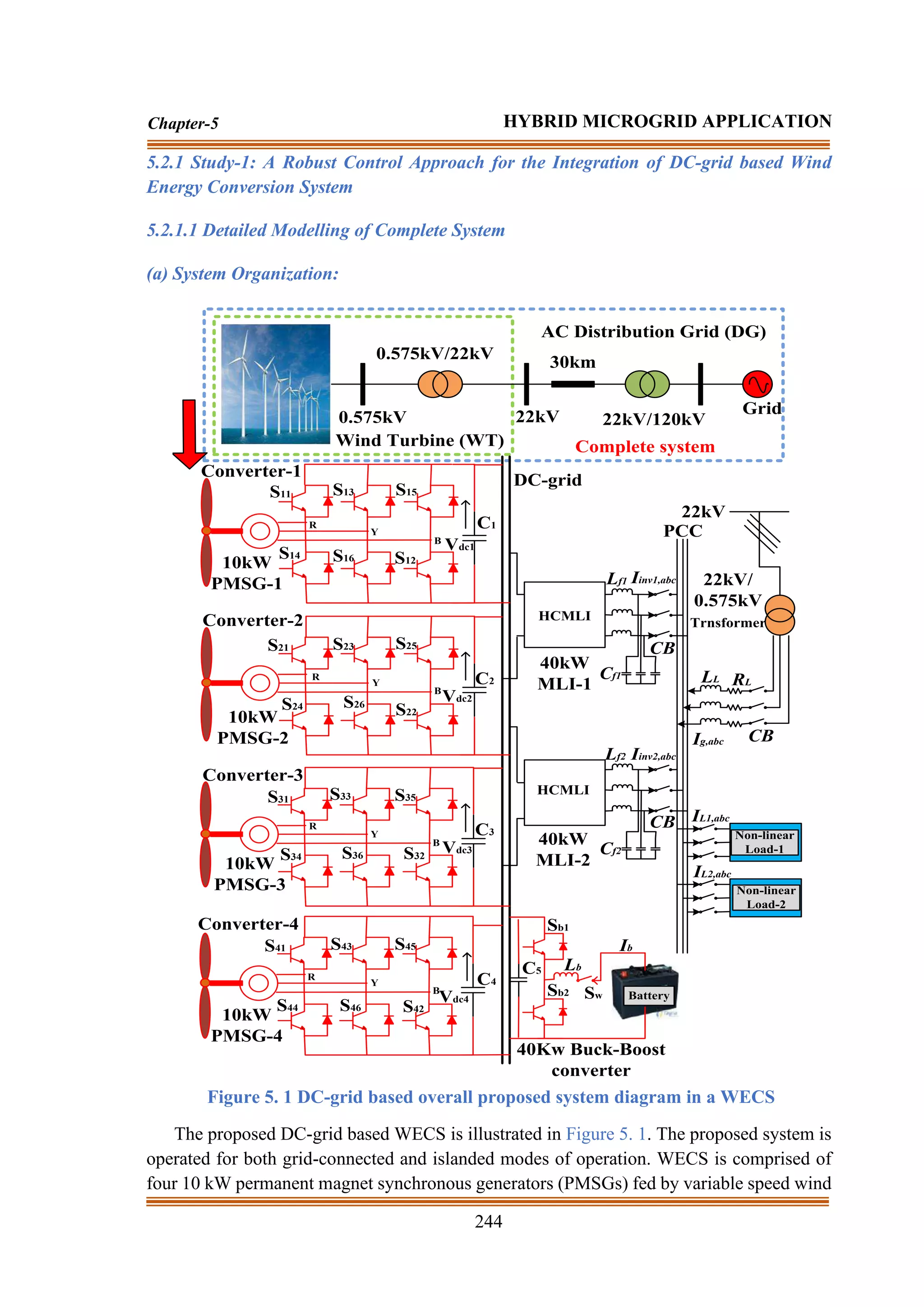
![245
Chapter-5 HYBRID MICROGRID APPLICATION
turbines (WTs), four three-phase ac-DC voltage source converters connected to each of the
PMSG outputs (converters 1, 2, 3, and 4), and two HCMLI (HCMLI-1, and HCMLI-2)
having the maximum 20kW capability each. A PMSG based WECS is chosen considering
the less cost factor, easy real-time implementation, and simple control structure due to the
absence of any DC excitation system. Proposed WECS decreases the requirements of
numerous inverters at the generating stations. The coordination of the power electronic
devices is monitored by the centralized energy management system (CEMS). Through a
centralized server, the CEMS checks and monitors the generation of wind power and
consumption of load power. CEMS also monitors and regulates both the inverter voltages to
an equal desired value for preventing excess circulating currents in between them. In addition
to that, CEMS is also responsible for other aspects of power management like unit
commitment, load forecasting, economic load dispatch, and better power quality, etc.
All key data like measuring the total area of the installation system by using smart meters,
tap positions of the transformers, and the movements of the circuit breakers (CBs) are sent
to the CEMS by using wire-line or wireless communications. The maximum wind power
(Popt,w) from each of the WTs is obtained as follows[212].
3
r
,
opt
opt
w
,
opt )
(
*
K
P
= (5.1)
3
opt
opt
,
P
opt )
R
(
A
C
2
1
K
= (5.2)
R
v
*
opt
r
,
opt
= (5.3)
where ‘Kopt’ is the optimum constant parameters, ‘ r
,
opt
’ is the optimum speed of the WT,
‘ opt
,
P
C ’ is the optimum turbine power coefficient, ‘ ’ is the density of air, ‘A’ is the swept
area of the rotor blade, ‘ opt
’ is the optimized tip speed ratio, ‘v’ is the speed of the wind,
and ‘R’ is the radius of the blade.
As shown in Fig.1 for the islanding mode of operation (IMO), a BES is integrated with
the WECS. The size of the battery is chosen as 80 Ah and linked with the DC-grid through
a 40kW bidirectional buck-boost converter [273]. The battery charging and discharging
operational mode is achieved during the grid-connected and islanded mode of operation
respectively. The energy constraint of the storage device is calculated based on state-of-
charge (SOC) limits and represented as:
SOCmin<SOC<SOCmax (5.4)
As presented in [317] and [274], the SOC of the BES is calculated through an estimation
method. During the fewer load demand, the battery will be charged by using the surplus
charge of the WTs and at high load demand or islanding conditions, the power is transmitted
from the battery.](https://image.slidesharecdn.com/dr-211204045233/75/Robust-Active-Power-Filter-Controller-Design-for-Microgrid-and-Electric-Vehicle-Applications-part-2-40-2048.jpg)
![246
Chapter-5 HYBRID MICROGRID APPLICATION
(b)Operation of the System:
During the grid-connected mode of operation (GMO), the WTs are responsible for
supplying the generated power to the loads without giving an extra burden to the distribution
grid. BES can be controlled to attain the load side requirement depending on the time of use
of electricity and the SOC of the battery [278-279].
During the islanded mode of operation (IMO), the CB is used to detach the microgrid
from the grid. In this case, the WTs and battery are the only existing sources to fulfill the
load demand. To balance the power, the battery is used to supply the deficit of active power
into the system. The power balance equations are represented as:
PWTs + Pbat = PL, syst + PL (5.5)
where PWTs is the active power of the WT. Pbat is the battery active power which is subjected
to the constraints of the battery maximum power (Pbat,max) that can be distributed at the
discharging mode of operation (Pbat<Pbat,max ). PL,syst and PL denote the power loss, and load
power respectively.
(c) Proposed HCMLI Topology:
SA1 SA2 SA3 SA4 SA5 SA6 SA7 SA8
SA1` SA2` SA3` SA4` SA5` SA6` SA7` SA8`
SB1 SB2 SB3 SB4 SB5 SB6 SB7 SB8
SB1` SB2` SB3` SB4` SB5` SB6` SB7` SB8`
SC1 SC2 SC3 SC4 SC5 SC6 SC7 SC8
SC1` SC2` SC3` SC4` SC5` SC6` SC7` SC8`
AC1 AC2 AC3 AC4
BC1 BC2 BC3 BC4
CC1 CC2 CC3 CC4
2
/
Vdc
2
/
Vdc
2
/
Vdc
4
/
Vdc
4
/
Vdc
4
/
Vdc
8
/
Vdc 16
/
Vdc
8
/
Vdc
8
/
Vdc
16
/
Vdc
16
/
Vdc
Lf
dc
V
Figure 5. 2 Schematic diagram of proposed HCMLI
The proposed HCMLI is designed with cascading a 3-level FCI and three floating
capacitor H-bridges. The 3-phase17-level HCMLI schematic diagram is illustrated in Figure
5. 2. As shown in Figure 5. 2, phase-A contains the switch pairs as [( 1
SA ,
1
SA ), ( 2
SA ,
2
SA ),
( 3
SA ,
3
SA ), ( 4
SA ,
4
SA ), ( 5
SA ,
5
SA ), ( 6
SA ,
6
SA ), ( 7
SA ,
7
SA ) and ( 8
SA ,
8
SA )], phase-B
contains the switch pairs as [( 1
SB ,
1
SB ), ( 2
SB ,
2
SB ), ( 3
SB ,
3
SB ), ( 4
SB ,
4
SB ), ( 5
SB ,
5
SB ), ( 6
SB ,
6
SB ), ( 7
SB ,
7
SB ) and ( 8
SB ,
8
SB )], and phase-C contains the switch pairs 9 as [( 1
SC ,
1
SC ), ( 2
SC ,](https://image.slidesharecdn.com/dr-211204045233/75/Robust-Active-Power-Filter-Controller-Design-for-Microgrid-and-Electric-Vehicle-Applications-part-2-41-2048.jpg)
![247
Chapter-5 HYBRID MICROGRID APPLICATION
2
SC ), ( 3
SC ,
3
SC ), ( 4
SC ,
4
SC ), ( 5
SC ,
5
SC ), ( 6
SC ,
6
SC ), ( 7
SC ,
7
SC ) and ( 8
SC ,
8
SC )] respectively.
The proposed hybrid inverter contains four capacitors in each phase like ( 1
AC , 2
AC , 3
AC , and
4
AC ), ( 1
BC , 2
BC , 3
BC , and 4
BC ), and ( 1
CC , 2
CC , 3
CC , and 4
CC ) respectively. As indicated in
Figure 5. 2, the pole voltages of the capacitors 1
AC , 1
BC , and 1
CC are fixed at the voltage level
of VDC/2, capacitors 2
AC , 2
BC , and 2
CC are fixed at the voltage level of VDC/4, capacitors 3
AC ,
3
BC , and 3
CC are fixed at the voltage level of VDC/8, and capacitors 4
AC , 4
BC , and 4
CC are
fixed at the voltage level of VDC/16 respectively.
In this topology, each of the cascaded H-bridges (CHBs) voltages can be added or
subtracted to the voltage of the previous stage. HCMLI voltage levels are determined by
adding the voltages of each stage of the inverter. Each pair of the switch contains two
different logic states as the top device are ON (indicated as ‘✓’) and the bottom device is
OFF (indicated as ‘’). For the above switching states, there are 256 (28
) switching
combinations are possible for the inverter operation. The voltage levels of HCMLI can be
determined by using one or more switching combinations (pole voltage redundancies). In the
case of the same pole voltages, by using the redundant switching combinations, the
capacitor’s current can be changed and the voltages of the capacitors can be controlled to
their set values. By using the above combinations, the balanced capacitor voltages at all load
currents and power factors instantly have been studied for 17 voltage levels. The voltage
levels are 0, VDC/16, 2VDC/16, 3VDC/16, 4VDC/16, 5VDC/16, 6VDC/16, 7VDC/16, 8VDC/16,
9VDC/16, 10VDC/16, 11VDC/16, 12VDC/16, 13VDC/16, 14VDC/16, 15VDC/16, and VDC.
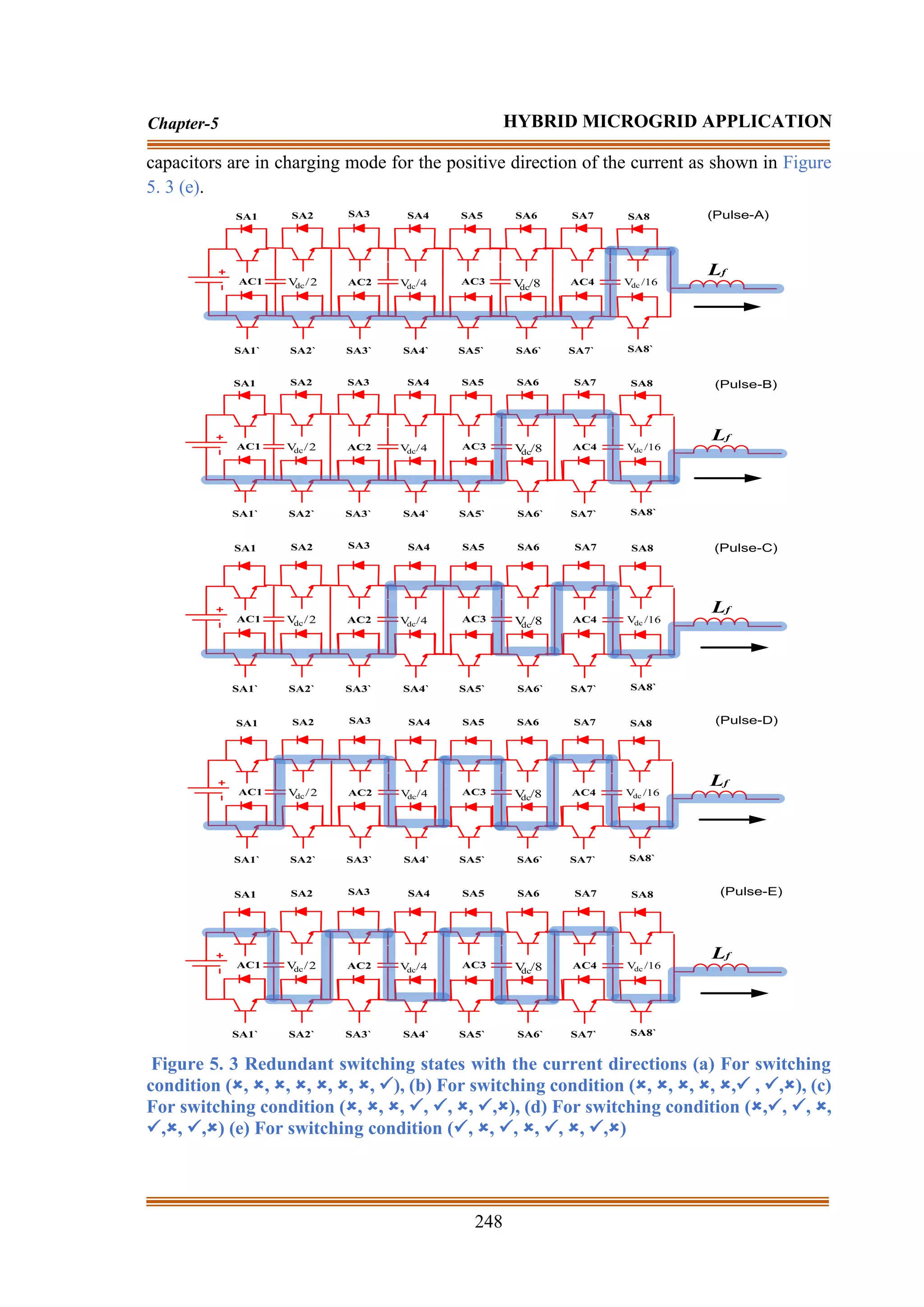
The HCMLI generates the 17-level output voltage by using 82 switching arrangements
as indicated in Chapter-5 Appendix-1 (Table.A.5). For positive current, the effect of 82
switching arrangements on every capacitor charging and discharging conditions (during that
period the pole is the source current as indicated in Figure 5. 3) is illustrated in the Chapter-
5 Appendix-1 (Table.A.5). For the negative current, the switching arrangements on the
capacitors are changed accordingly. For example, while the controller needs a pole voltage
of VDC/16, in HCMLI five unlike redundant switching arrangements are possible as indicated
in Figure 5. 3. Each switching arrangement has a different outcome on the state charge of the
capacitors. In Figure 5. 3 (a), at (, , , , , , , ✓) switching state (as shown in
Table.A.5), the capacitor C4 is at discharging mode. To balance the C4 voltage and to fetch
the voltage at its set value (VDC/16), one of the other four switching arrangements is selected
as shown in Figure 5. 3 (b-e). As shown in Figure 5. 3 (b), for (, , , , , ✓, ✓, )
switching state, the current direction of C4 is reversed and the capacitor C4 is charged.
However, due to the above switching state, the capacitor C3 is discharged. As illustrated in
Figure 5. 3 (c), to charge C3 and to balance the pole voltage, the switching redundancy (,
, , ✓, ✓, , ✓,) is chosen. Similarly, due to the charging of C3, C2 is discharged. Based
on the C1 charging condition, to charge C2 one of the switching arrangements is chosen
between Figure 5. 3 (d) and Figure 5. 3 (e). If the switching arrangement is (,✓, ✓, , ✓,,
✓,), the C1 is in the discharging mode and the state of charge of all other capacitors is shown
in Figure 5. 3 (d). Finally, for the switching combinations (✓,,✓, , ✓, , ✓,), all the](https://image.slidesharecdn.com/dr-211204045233/75/Robust-Active-Power-Filter-Controller-Design-for-Microgrid-and-Electric-Vehicle-Applications-part-2-42-2048.jpg)
![250
Chapter-5 HYBRID MICROGRID APPLICATION
current is controlled to be zero by which the PMSG can deliver only active power. By
analyzing the reference and the actual values of current, the current error signal d
I
and q
I
are computed. Then by using the dq-abc transformation, the corresponding error signal is
given as input to the repetitive controller to produce the appropriate pulse width modulation
(PWM) signal [154]. Due to the use of a constant wind speed ventilation fan, the wind speed
is constant all the time. Therefore, the proposed ac-DC converter approach easily eliminates
the need of maximum power point (MPP) strategies for the regulation of speed and
electromagnetic torque of the wind turbine. Due to the elimination of MPP strategies, the ac-
DC converter control strategies become simpler and reduce the computational burden easily.
(b) Control Approach for Battery Energy Storage (BES) Device:
*
bat
P
bat
P
+
-
+
-
demand
,
g
P
*
g
P
*
g
demand
,
g Q
Q =
2
gq
2
gd
gq
*
gd
*
*
q
2
gq
2
gd
gq
*
gd
*
*
d
V
V
V
P
V
Q
I
V
V
V
Q
V
P
I
+
−
=
+
−
=
*
d
I
*
q
I
+
-
abc
,
g
V
abc
dq
gd
V
gq
V
Total
,
WT
P
+
-
ref
,
dcg
V
+
-
LPF
g
,
dc
V
PI
abc
dq
PWM
1
S
2
S
e
,
dc
V
d
I
e
,
d
I
rest
P
e
,
b
P
Figure 5. 5 Control approach for BES
The BES control strategies mostly depend upon the DC-link voltage of the DC-grid, battery
SOC conditions, and grid/load demand. The complete control structure of BES is presented
in Figure 5. 5. Therefore, to increase battery durability, it is necessary to regulate the SOC
of the battery during GMO and IMO conditions. The detailed SOC management schemes are
presented in [273-278]. In the proposed approach, the reference battery power ( *
bat
P ) is
selected as per the SOC limit during both GMO and IMO conditions. At first, the grid active
and reactive power demand ( demand
,
g
P ) is fulfilled by the total generated power ( Total
,
WT
P
) of the wind turbine. According to the higher and lower limit of battery SOC, the charging
and discharging conditions are set. By comparing the rest power demand ( rest
P ) and battery
power error ( e
,
b
P ), the reference active grid power ( *
g
P ) is computed. The reactive power
demand ( demand
,
g
Q ) of the grid is equal to the reference reactive power ( *
g
Q ) of the system.](https://image.slidesharecdn.com/dr-211204045233/75/Robust-Active-Power-Filter-Controller-Design-for-Microgrid-and-Electric-Vehicle-Applications-part-2-45-2048.jpg)
![251
Chapter-5 HYBRID MICROGRID APPLICATION
After getting reference active and reactive power, the obtained powers are converted to
reference dq current component ( *
d
I and *
q
I ) [278]. The ac-load is connected to the ac-grid.
At the time of IMO, the ac-grid is detached from the main grid. To properly avail the charging
and discharging condition, the DC-grid information is also essential. Therefore, DC-grid
voltage ( g
,
dc
V ) is compared with the total DC-grid reference ref
,
dcg
V voltage, to generate
the appropriate voltage error ( e
,
dc
V ). e
,
dc
V is passed through the PI regulator, to generate
the linear active current component ( d
I ). The d
I is compared with *
d
I , to generate the error
in the active current component ( e
,
d
I ). After generating e
,
d
I and *
q
I component, the current
components are transformed to abc current component for generating appropriate pulses for
the battery converter operation.
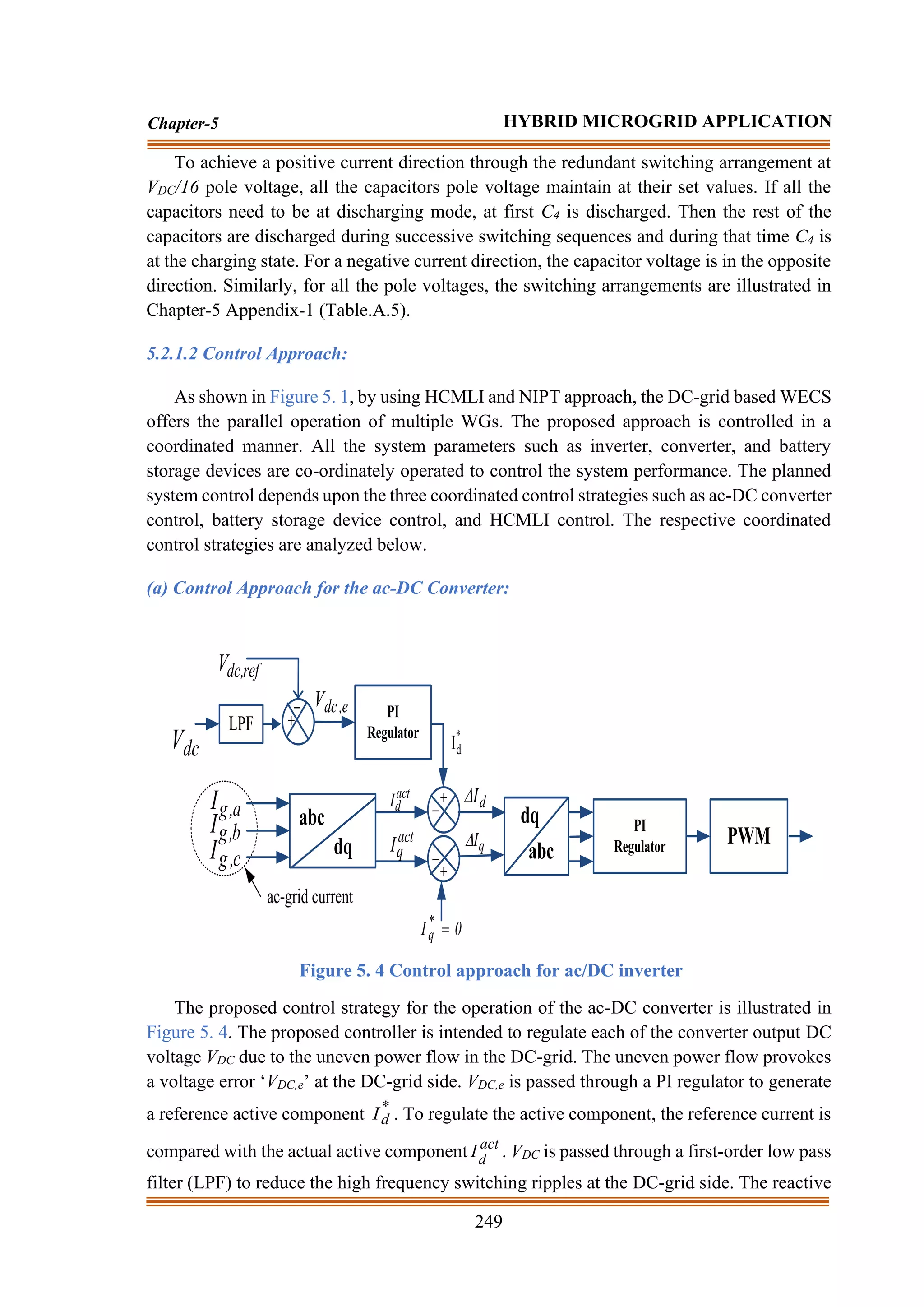
(c) Control Approach for a DC-ac Inverter:
The proposed NIPT approach is adopted for the inverter operation by generating the
actual reference current signal. The proposed approach easily separates the harmonics and
unbalanced components as shown in Figure 5. 6. After easily separating the oscillating
component, the positive sequence current component is used to generate the pulses for
HCMLI operation. The current component of the load and the voltage component of the grid
is transformed by the
−
abc transformation as follows.
=
−
−
−
=
0
g
g
g
0
0
g
g
g
abc
,
g
V
V
V
C
V
V
V
2
1
2
3
2
1
2
1
2
3
2
1
2
1
0
1
3
2
V
(5.6)
=
0
,
L
,
L
,
L
0
abc
,
L
I
I
I
C
I
(5.7)
The component of the grid voltage (
,
g
V ,
,
g
V ), and the load current (
,
l
I ,
,
l
I ) are
computed by neglecting the zero sequence components and represented as:
=
−
−
−
=
−
c
,
g
b
,
g
a
,
g
1
c
,
g
b
,
g
a
,
g
,
g
,
g
V
V
V
C
V
V
V
2
3
2
3
0
2
1
2
1
1
3
2
V
V
(5.8)
=
−
c
,
L
b
,
L
a
,
L
1
,
L
,
L
I
I
I
C
I
I
(5.9)](https://image.slidesharecdn.com/dr-211204045233/75/Robust-Active-Power-Filter-Controller-Design-for-Microgrid-and-Electric-Vehicle-Applications-part-2-46-2048.jpg)

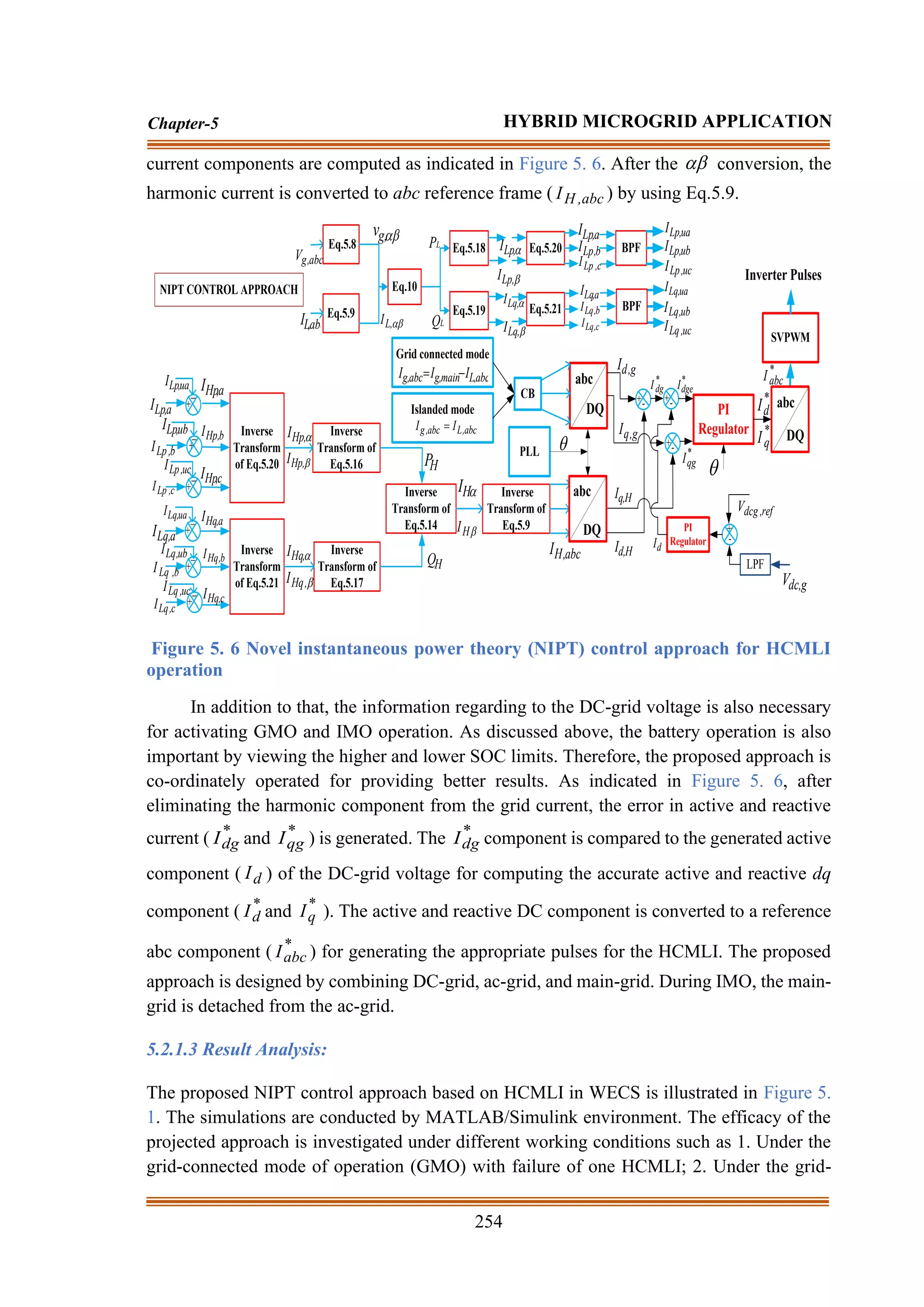
![255
Chapter-5 HYBRID MICROGRID APPLICATION
connected mode of operation with the integration of AC-DC converter; 3. Under the islanded
mode of operation (IMO). The system parameters considered in the simulation are
enumerated in the Appendix. The detailed data related to the distribution line are taken from
[287].
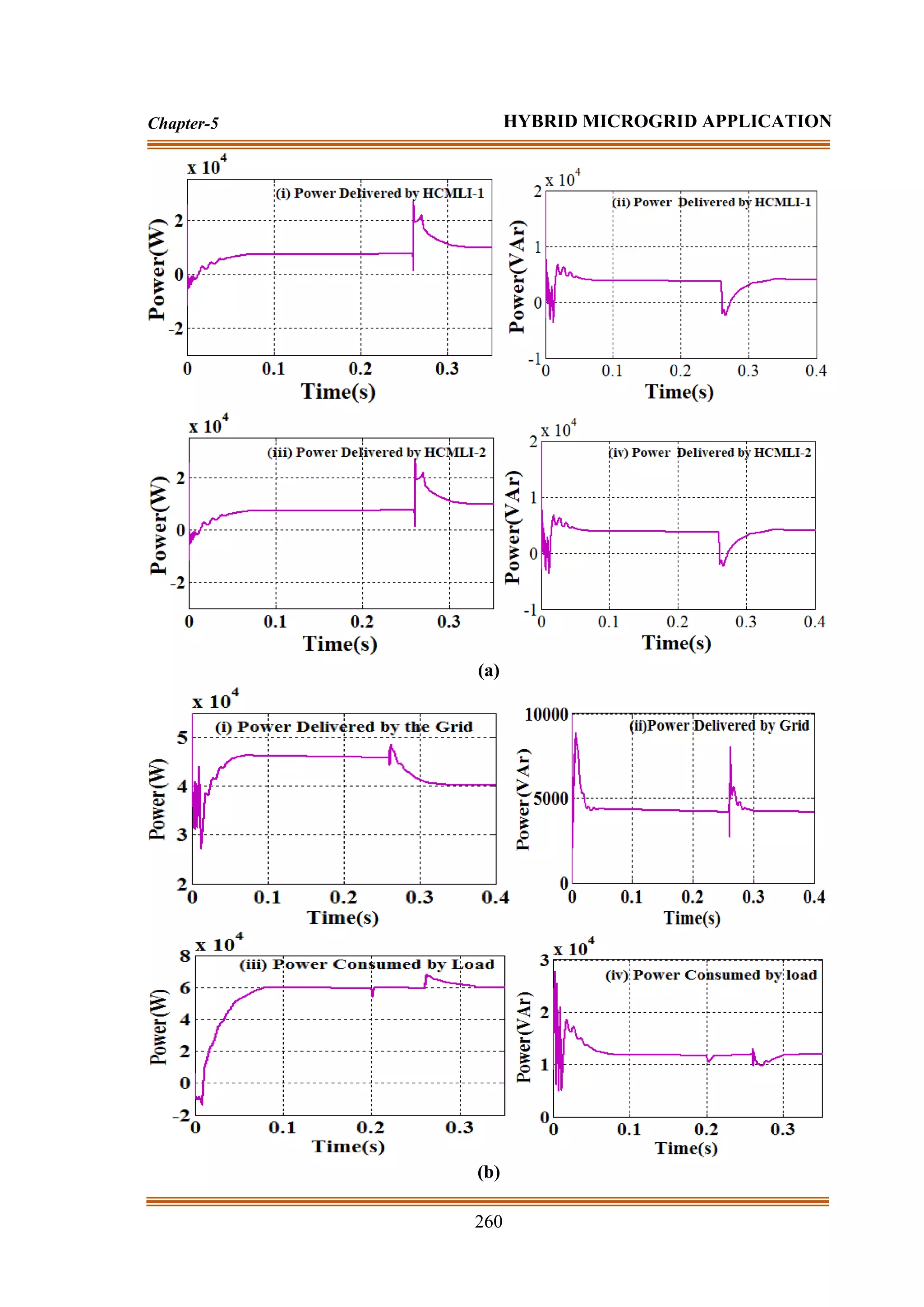
(a) First Scenario:
(a)](https://image.slidesharecdn.com/dr-211204045233/75/Robust-Active-Power-Filter-Controller-Design-for-Microgrid-and-Electric-Vehicle-Applications-part-2-50-2048.jpg)
![267
Chapter-5 HYBRID MICROGRID APPLICATION
5.2.2 Study-2: A Novel Centralized Energy Management Approach for Power Quality
Improvement
5.2.1.1 Detailed operation of centralised management system (CEMS):
Solar
PV
S1
Boost Converter
DS D1
CS
L1
Lb
Vdc
S3
S2
C2
Battery
C1
Cb
Ib
Vdc
Buck-Boost Converter
S11 S13 S15
S14 S16 S12
Lf
Cf
CB
Voltage Source Inverter
dc-grid ac-grid
Centralized Energy Management Approach (CEMA)
Dc-load
Ac-load
Boost
Converter Pulses
Buck-Boost
Converter Pulses
Inverter Pulses
CB
CB
Ls Rs
ac-distribution
Grid
Transformer
P l
,
dc
P l
,
ac
Ps
Pb
Vs Is
Vs Is Ib
Vb
Vb SOC CB Ps Pb P l
,
dc P l
,
ac
Pg
Pg
Pac
Pac
V abc
,
g
V abc
,
g
Point of common
coupling (PCC)
Figure 5. 10 Proposed CEMS for solar-battery based microgrid
A typical arrangement of a combined solar-battery based hybrid grid (ac/DC) system is
demonstrated in Figure 5. 10. The proposed HMS is comprised of a solar array, BES device,
a bidirectional VSI, a DC-DC boost converter (BC), and a bidirectional buck-boost converter
(BBC) [318-319]. To extract optimum power, a BC is directly connected to the solar array,
and to avail optimal charging and discharging condition, a BBC is connected to the BES. For
the reliable power supply, a centralized DC-ac VSI is integrated between the ac and DC
microgrid. The DC and ac grid-based HMS facilitate the direct integration of the DC and ac
load without requiring any conversion device. From a real-time application point of view,
the DC-load examples are hybrid electric vehicles, laptop batteries, adapters, batteries,](https://image.slidesharecdn.com/dr-211204045233/75/Robust-Active-Power-Filter-Controller-Design-for-Microgrid-and-Electric-Vehicle-Applications-part-2-62-2048.jpg)
![268
Chapter-5 HYBRID MICROGRID APPLICATION
chargers, and office buildings, etc. The designed hybrid system is connected to the utility
grid through a (208V:1.2kV) step-up transformer. To avail both grid-following and grid-
forming mode, a circuit breaker (CB) is connected to the HMS. During the severe fault at the
ac-grid, the CB may open to avoid the back feeding of current from the utility grid [320].
The projected HMS shown in Fig.1 is worked both grid-following and grid-forming
conditions. A similar type of undertaken system configuration is also widely employed and
tested in [315-316]. In this proposed approach, the projected CEMS is worked as a supervised
control module which regulates the active parameters such as solar voltage (Vs), solar current
(Is), battery current (Ib), battery voltage (Vb), grid voltage (Vg), state of charge (SOC), circuit
breaker (CB), solar power (Ps), battery power (Pb), ac-grid power (Pg), DC-load power
(PDC,l), and ac-load power (Pac,l), etc. As per the desired conditions, the proposed CEMS
selects appropriate control architecture to tackle the deteriorations and to provide a reliable
power supply. Though the proposed CEMS is modeled by using a solar-battery HMS as
indicated in Figure 5. 10, with proper modifications and appropriate technique there are also
other possibilities like decentralized VSI design or multiple energy storage device
integration. For both operating conditions, the detailed control architecture flow charts of the
proposed CEMS are demonstrated in Figure 5. 11(a-b).
As presented in Figure 5. 10, the solar-battery based microgrid system is connected to the
utility grid through a CB. According to the requirement, deteriorations, and the plans of both
microgrid and utility, the CEMS decides by which mode and control technique the hybrid
system to be operated. As illustrated in Figure 5. 11(a-b), to avail a smooth power transfer in
both of the modes, the battery SOC functions such as higher
SOC
SOC ,
higher
lower SOC
SOC
SOC
, and lower
SOC
SOC are necessary to monitor. The higher
(90%) and lower (10%) values of SOC are regularly monitored, to avoid overcharging and
discharging conditions for increasing the life cycle of the battery [321].
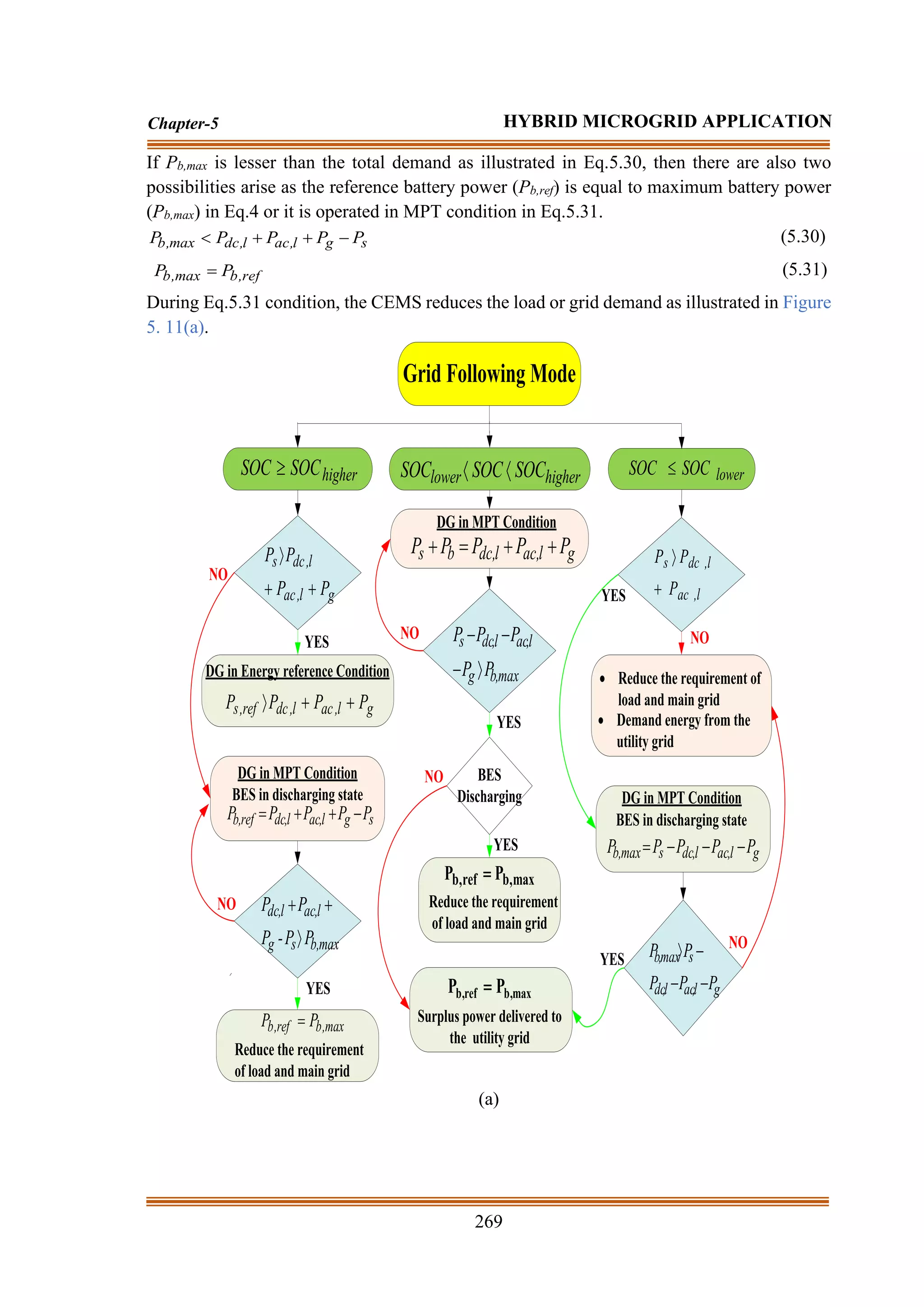
(a) Grid-following Mode Architecture:
Figure 5. 11(a) illustrates the grid following mode architecture flow chart by which the
projected CEMS regulates the undertaken HMS. A detailed description of the flowchart is
presented below.
(i) During higher
SOC
SOC Condition:
During that period, there are two possibilities to regulate the HMS such as energy reference
condition (ERC) in Eq.5.28 and MPT condition in Eq.5.29. To avail the real power flow from
source to load and grid, the HMS must operate according to Eq.5.28.
g
l
,
ac
l
,
dc
s P
P
P
P +
+
(5.28)
If Eq.5.28 condition satisfies then the HMS is operated in ERF condition otherwise the
system is operated in MPT condition and the battery is used to start discharging. In MPT
conditions to fulfill the desired load demand, the HMS must operate according to Eq.5.29.
s
g
l
,
ac
l
,
dc
ref
,
b P
P
P
P
P −
+
+
= (5.29)](https://image.slidesharecdn.com/dr-211204045233/75/Robust-Active-Power-Filter-Controller-Design-for-Microgrid-and-Electric-Vehicle-Applications-part-2-63-2048.jpg)

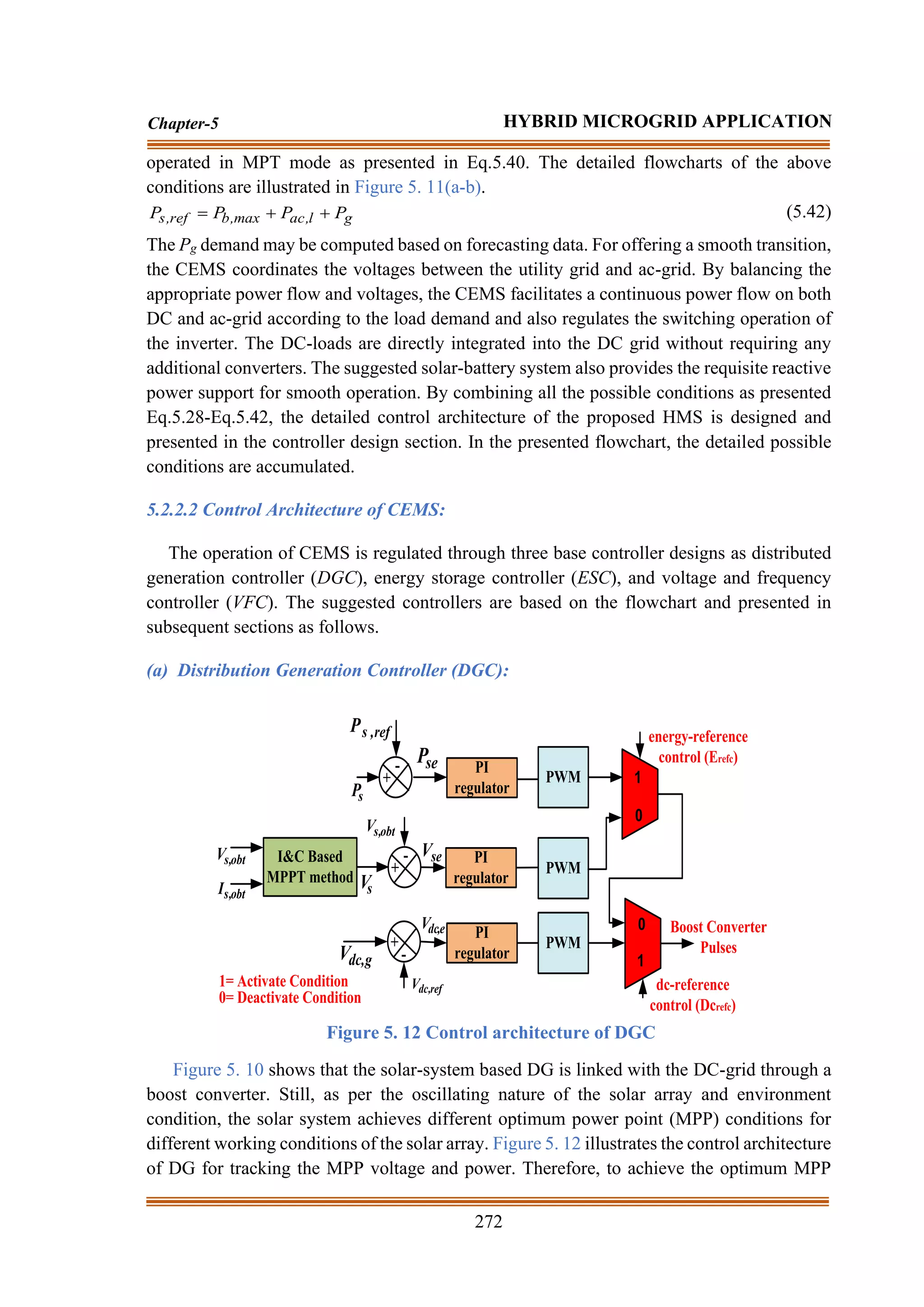
![273
Chapter-5 HYBRID MICROGRID APPLICATION
condition, the Incremental Conductance (IC) based MPT algorithm is used [154,289,212] to
track maximum power under different irradiance and temperature condition [1]. The
instantaneous voltage and current result of the solar is denoted as Vs,obt, and Is,obt respectively.
The energy-reference control (Erefc) mode is activated by comparing the Ps and the reference
of solar power (Ps,ref). The DC-reference control (DCrefc) mode is activated by comparing the
DC-grid voltage (VDC,g) and the reference DC-grid voltage (VDC,ref). Depending on the test
scenarios, the proposed DGC controller is operated by considering three important factors
such as MPT control, Erefc, and DCrefc mode. After comparing the instantaneous signals with
the reference signals, the error signals such as an error in power (Pse), error in solar voltage
(Vse), and error in DC grid voltage (VDC,e) are passed through the PI regulator to linearize the
outputs and used to provide the necessary pulses for the converter operation.
For example, in Grid forming mode, if l
ac,
l
dc,
mpp
,
s P
P
P +
and the BES is fully charged
(Pb >Pb,max), the proposed CEMS generates the control commands such that the Erefc = 1, and
DCrefc = 0. As shown in Figure 5. 11(a-b), due to the above command the solar array is set to
work in the Erefc mode to produce the pulses for boost converter operation. In this case, to
balance the power flow, the CEMS will choose the appropriate Ps,ref for the solar array by
selecting the proper Vs,obt. The Vs,obt is lying in between the open-circuit voltage (Voc) and the
MPP voltage (Vs). As VDC,g is controlled through the energy storage device buck-boost
converter then in this condition, the voltage across the grid is maintained constant even under
solar power fluctuation situations. In addition to that when the battery is inactive (under fault
condition), the boost converter has shifted the power flow to maintain the DC-grid voltage
for a continuous power supply to the load by giving the command Erefc=0 and DCrefc =1.
Therefore, in this condition, only DCrefc is activated. In the MPP case, the proposed CEMS
generates the control commands Erefc= 0 and DCrefc=0, where the real-time voltage (Vs.obt)
and current (Is,obt) values of the solar array are computed and sent to the MPT module for
generating the maximum power point voltage (Vs). The DGC controller is designed by
considering the above three conditions as illustrated in Figure 5. 12. Note that the
simultaneous activation of Erefc and DCrefc is not relevant.
(b) Energy Storage Controller (ESC):
>0?
ref
,
b
P
Y
N
0
T
,
1
T 2
1 =
=
1
T
,
0
T 2
1 =
=
+
-
+-
b
P 0
1
PI
Controller
PWM
g
,
dc
V
ref
,
dc
V
1
T
2
T
2
S
3
S
dc-reference
control (Dcrefc)
1= Activate Condition
0= Deactivate Condition
Figure 5. 13 Control architecture of ESC](https://image.slidesharecdn.com/dr-211204045233/75/Robust-Active-Power-Filter-Controller-Design-for-Microgrid-and-Electric-Vehicle-Applications-part-2-68-2048.jpg)
![275
Chapter-5 HYBRID MICROGRID APPLICATION
)
V
2
1
V
2
1
V
(
3
2
V c
,
L
b
,
L
a
,
L
L −
−
=
(5.43)
)
V
2
3
V
2
3
(
3
2
V c
,
L
b
,
L
L −
=
(5.44)
)
I
2
1
I
2
1
I
(
3
2
I c
,
L
b
,
L
a
,
L
L −
−
=
(5.45)
)
I
2
3
I
2
3
(
3
2
I c
,
L
b
,
L
L −
=
(5.46)
L
L
L
L
L I
V
I
V
P +
= (5.47)
To supress the limitations of the numerical LPF, in the proposed approach a mathematical
average technique (MAT) is suggested to obtain the filtered DC load power (PL,f). The
proposed MAT is presented as follows.
=
T
0
L
f
,
L dt
P
T
1
P (5.48)
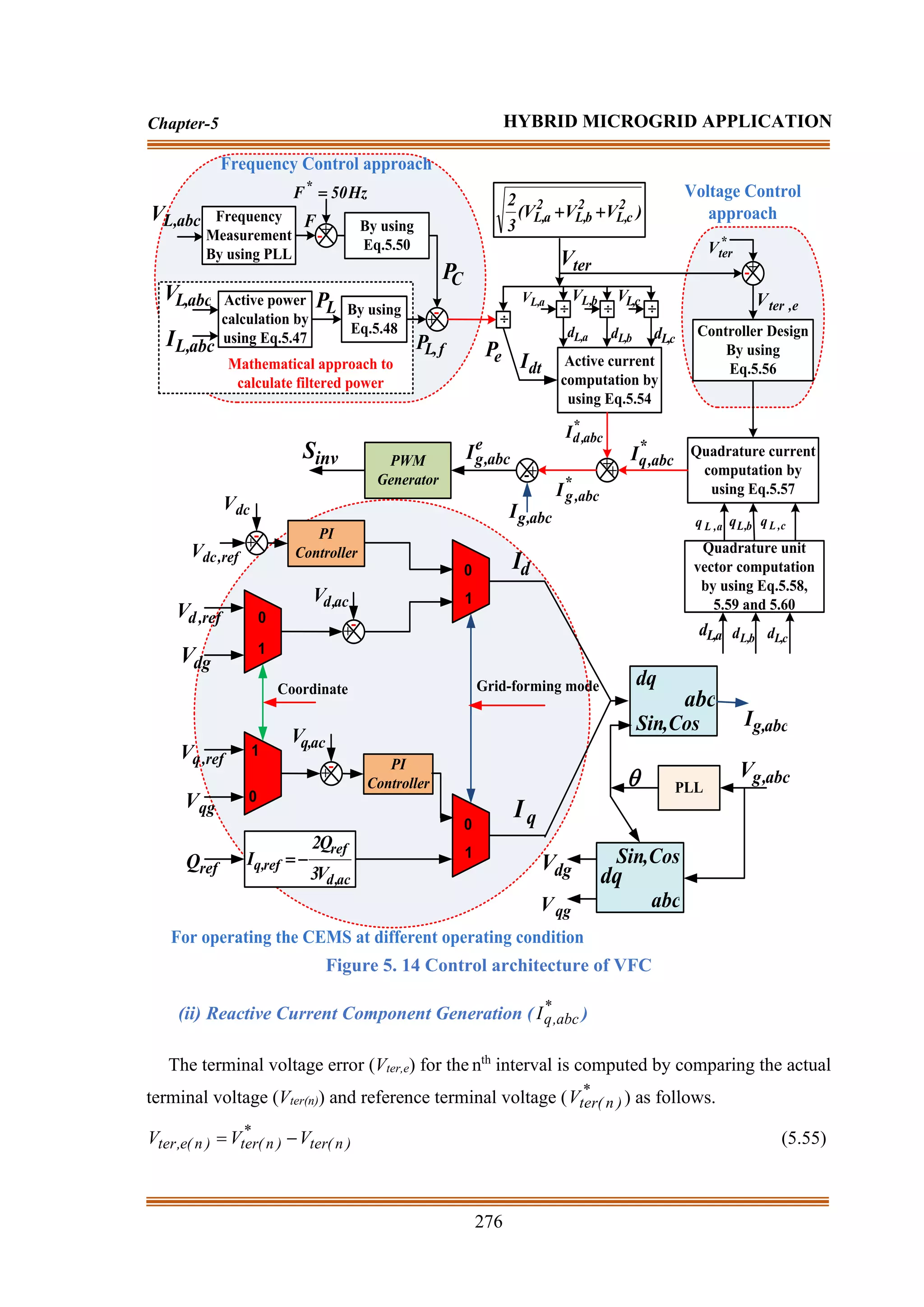
T denotes the total time duration of the circuit operation. As illustrated in Figure 5. 14, the
VL,abc is passed through PLL to produce the F. F*
of the system is chosen as 50Hz. Fe is
computed as:
)
n
(
F
)
n
(
F
)
n
(
F *
e −
= (5.49)
For nth
sampling instant, the output of frequency error is passed through the PI controller to
generate PC as follows.
)
n
(
F
K
)}
1
n
(
F
)
n
(
F
{
K
)
1
n
(
P
)
n
(
P e
IF
e
e
PF
C
C +
−
−
+
−
= (5.50)
where KPF and KIF denote as the proportional and integral frequency constant of the PI
controller respectively. The detailed controller design procedure is presented in [3], [5], and
[25]. The instantaneous load terminal voltage (Vter) is computed as:
2
1
2
c
,
L
2
b
,
L
2
a
,
L
ter )
V
V
V
(
3
2
V
+
+
= (5.51)
By using the PC, PL,f, and Vter, the active current component (Idt) is computed as:
ter
C
f
,
L
dt
V
3
)
P
P
(
2
I
−
= (5.52)
The active unity amplitude parameters (dL,a, dL,b, and dL,c) depend upon the instantaneous
load voltage (VL,abc) and the terminal amplitude load voltage (Vter).
The unity amplitude parameters are presented as:
ter
a
,
L
a
,
L
V
V
d = ;
ter
b
,
L
b
,
L
V
V
d = ; and
ter
c
,
L
c
,
L
V
V
d = (5.53)
From Eq.5.38, the generated instantaneous reference active current can be computed as:
a
dt
*
da d
I
I = ; b
dt
*
db d
I
I = ; and c
dt
*
dc d
I
I = (5.54)](https://image.slidesharecdn.com/dr-211204045233/75/Robust-Active-Power-Filter-Controller-Design-for-Microgrid-and-Electric-Vehicle-Applications-part-2-70-2048.jpg)
![278
Chapter-5 HYBRID MICROGRID APPLICATION
(Vdg and Vqg), the angle is generated by using the PLL block. After the breaker operation
as shown in Figure 5. 14, Vdg and Vqg are chosen as the reference voltage for the ac-grid
voltage.
To avoid the overloading condition, it is essential to regulate the dq current component (Id
and Iq). After generating the proper Id and Iq current component, it is converted to abc current
component (Ig,abc). As discussed above, the reference current signal ( *
abc
,
g
I ) is produced.
To generate the error signal ( e
abc
,
g
I ), the Ig,abc, and *
abc
,
g
I currents are compared and passed
through a PWM controller to produce the appropriate pulses for inverter operation.
5.2.2.3 Result Analysis:
To examine the performance of the proposed HMS and CEMS, different case studies are
carried out through the MATLAB/ Simulink environment. The overall configuration of the
designed system model is shown in Figure 5. 10. The solar system is tested under a standard
testing condition (STC) of irradiance =1000W/m2
and temperature = C
25
. The size of the
nickel-cadmium (Ni-cd) characteristics-based battery is chosen according to the IEEE 1562-
2007 standard [322]. The battery is chosen such that it can facilitate 5 days of independent
operation for 150kW load capacity under changing environmental conditions. The
undertaken simulated parameters of the proposed HMS are presented in Chapter-5
Appendix-1 (Table.A.6). The suggested CEMS regulates the system performance and
operates the data according to the requirement as shown in Figure 5. 11 (a-b). As per the
situation raised, CEMS regulates the switches of the inverter and converter to facilitate the
system operation for both grid-following and grid-forming mode as illustrated in Figure 5.
11 (a-b) flowchart. The proposed approach provides a complete solution to maintain the
continuity of power flow as per the requirement. The designed HMS model is tested by using
CEMS and without CEMS. The obtained results are compared with each other to show the
existence of proposed CEMS over without CEMS.
(a) Grid-following Operating Condition:
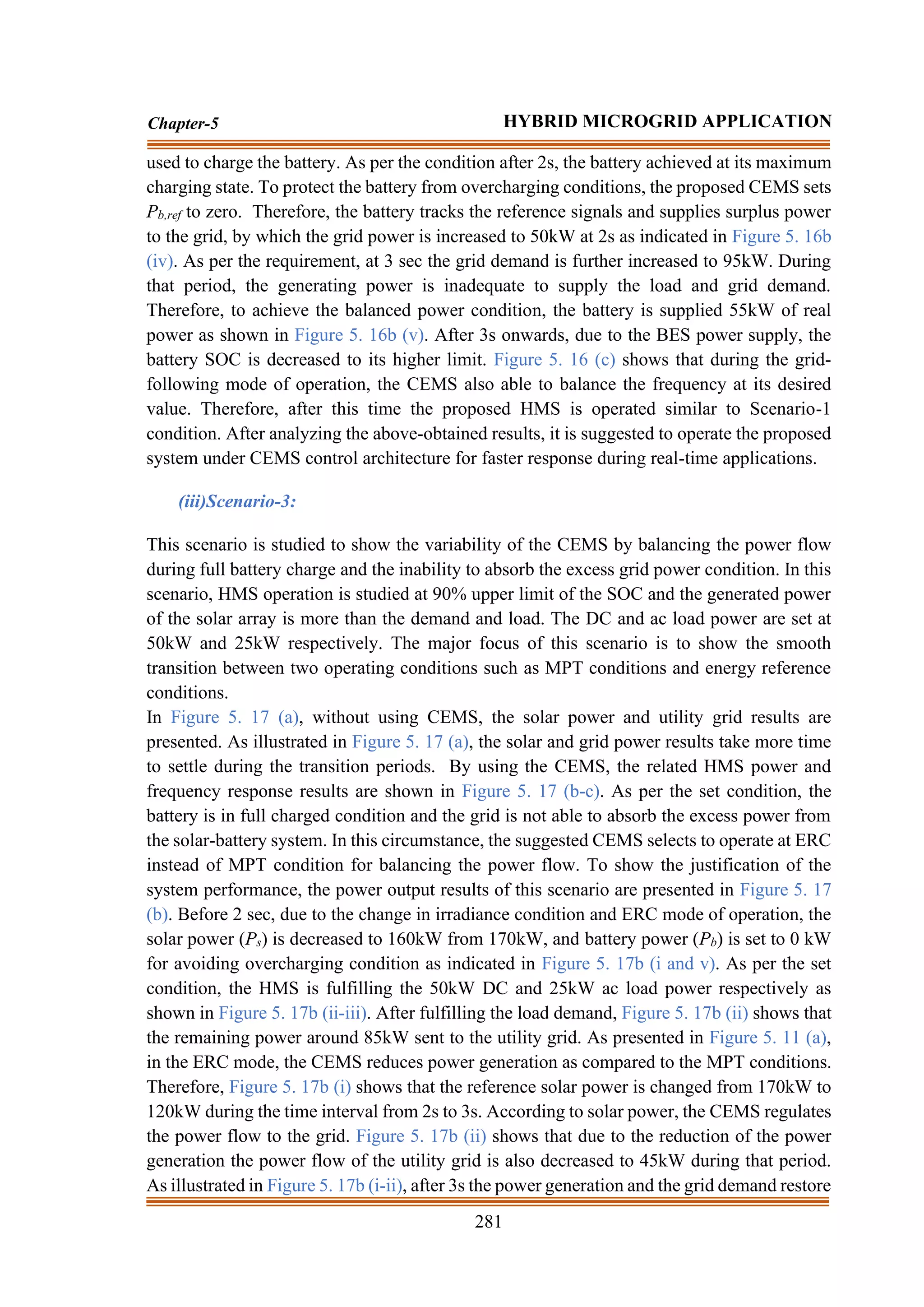
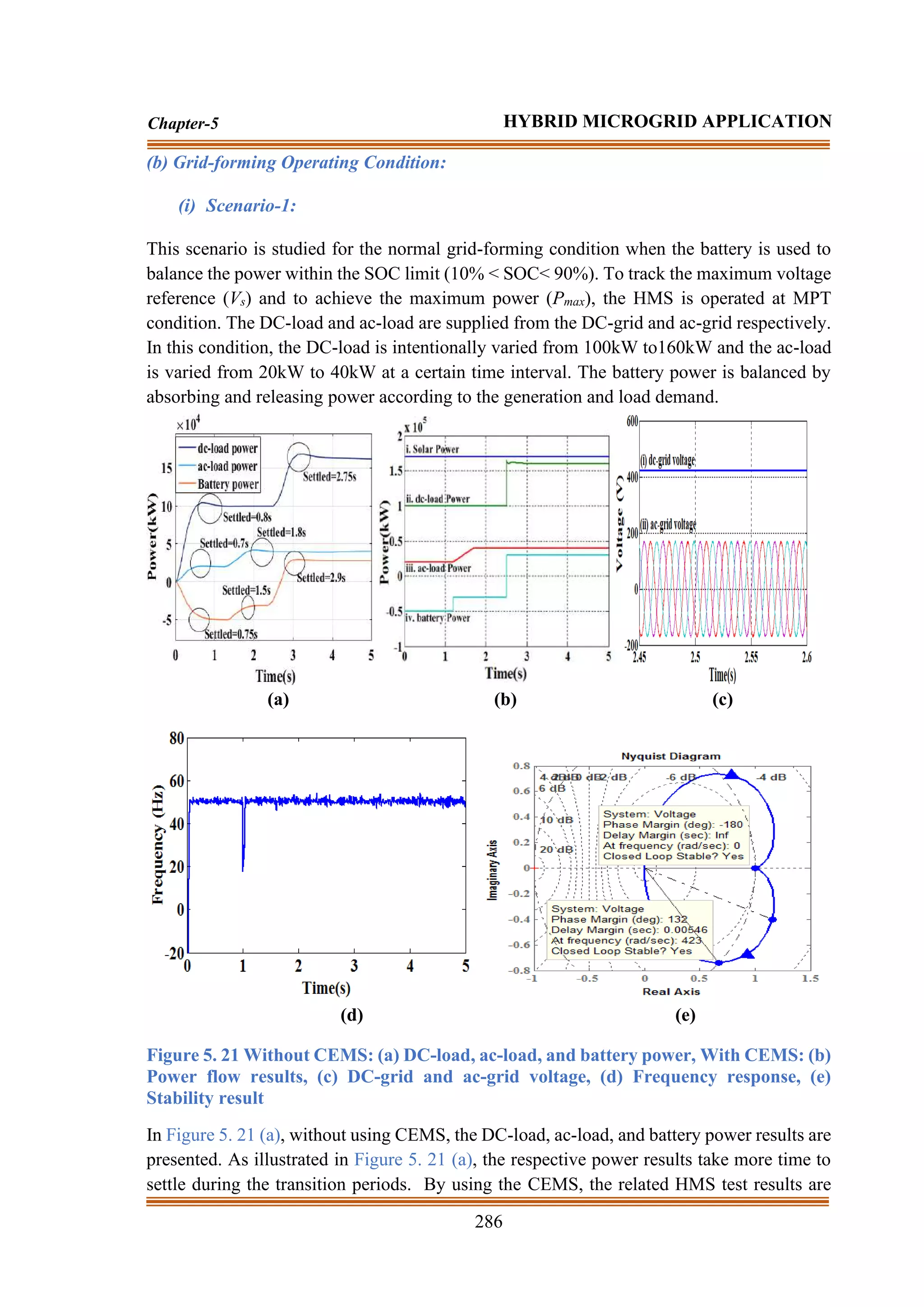
(i) Scenario-1:
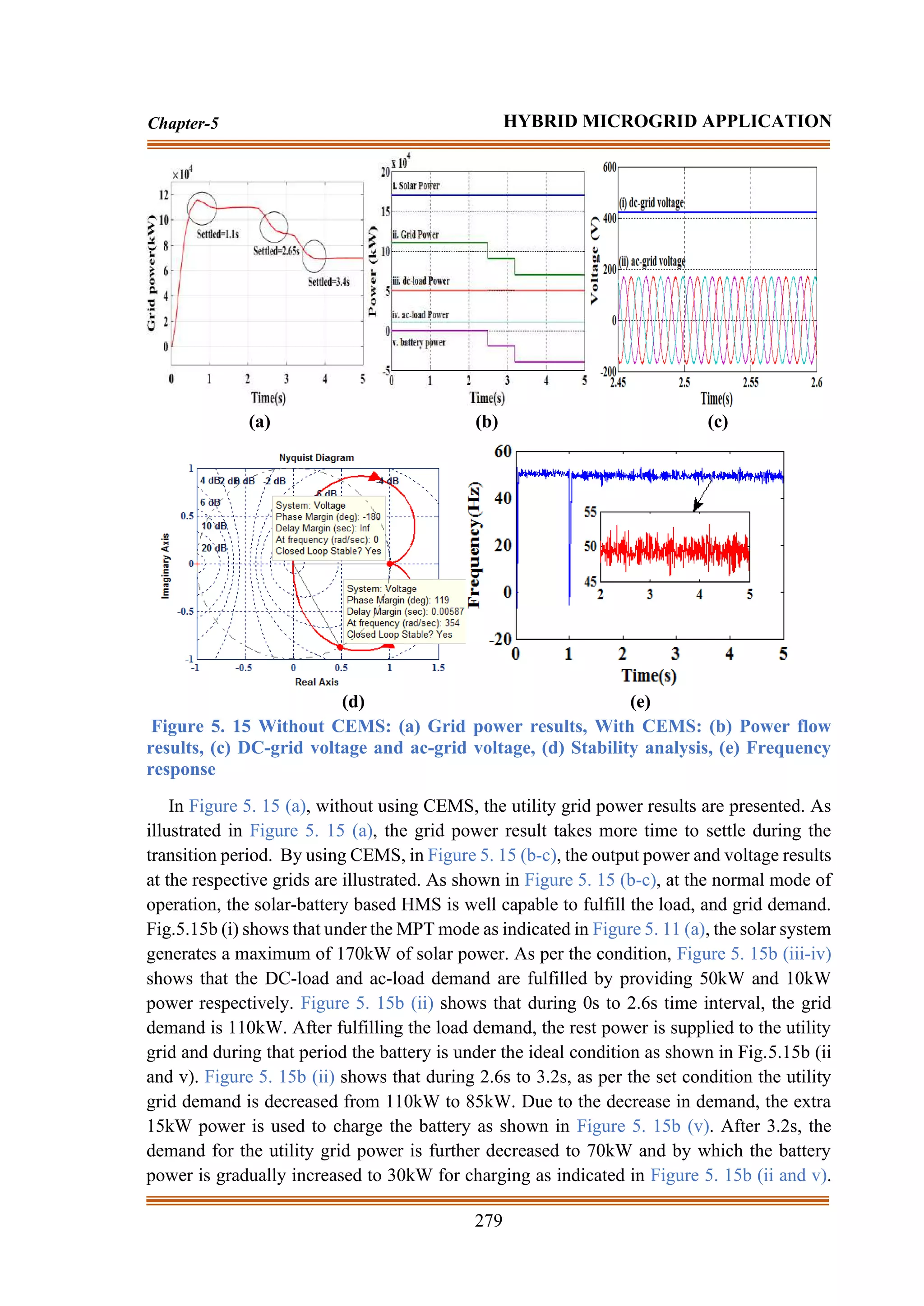
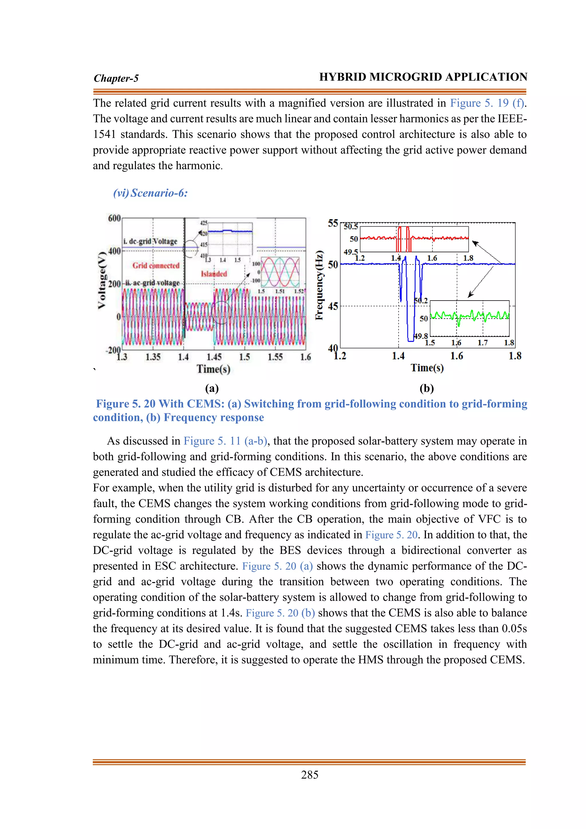
This scenario is studied for the normal grid-following condition when the battery is used to
regulate the power within the SOC limit (10% < SOC< 90%) as illustrated in Figure 5. 11
(a). According to the proposed DGC, the maximum voltage reference (Vs) and maximum
power (Pmax) are tracked by using the I&C MPT algorithm. The DC-loads and ac-loads are
supplied from the DC-grid and ac-grid respectively. In this condition, the DC-load and ac-
load are set 50kW and 10kW respectively. To show the variability of the supervised control
strategy and BES working conditions, the grid demand is intentionally varying from 110kW-
85kW-70kW at a specific time interval. According to the ESC, the battery power is balanced
by absorbing and releasing the power as per the generation, load, and utility grid demand.](https://image.slidesharecdn.com/dr-211204045233/75/Robust-Active-Power-Filter-Controller-Design-for-Microgrid-and-Electric-Vehicle-Applications-part-2-73-2048.jpg)
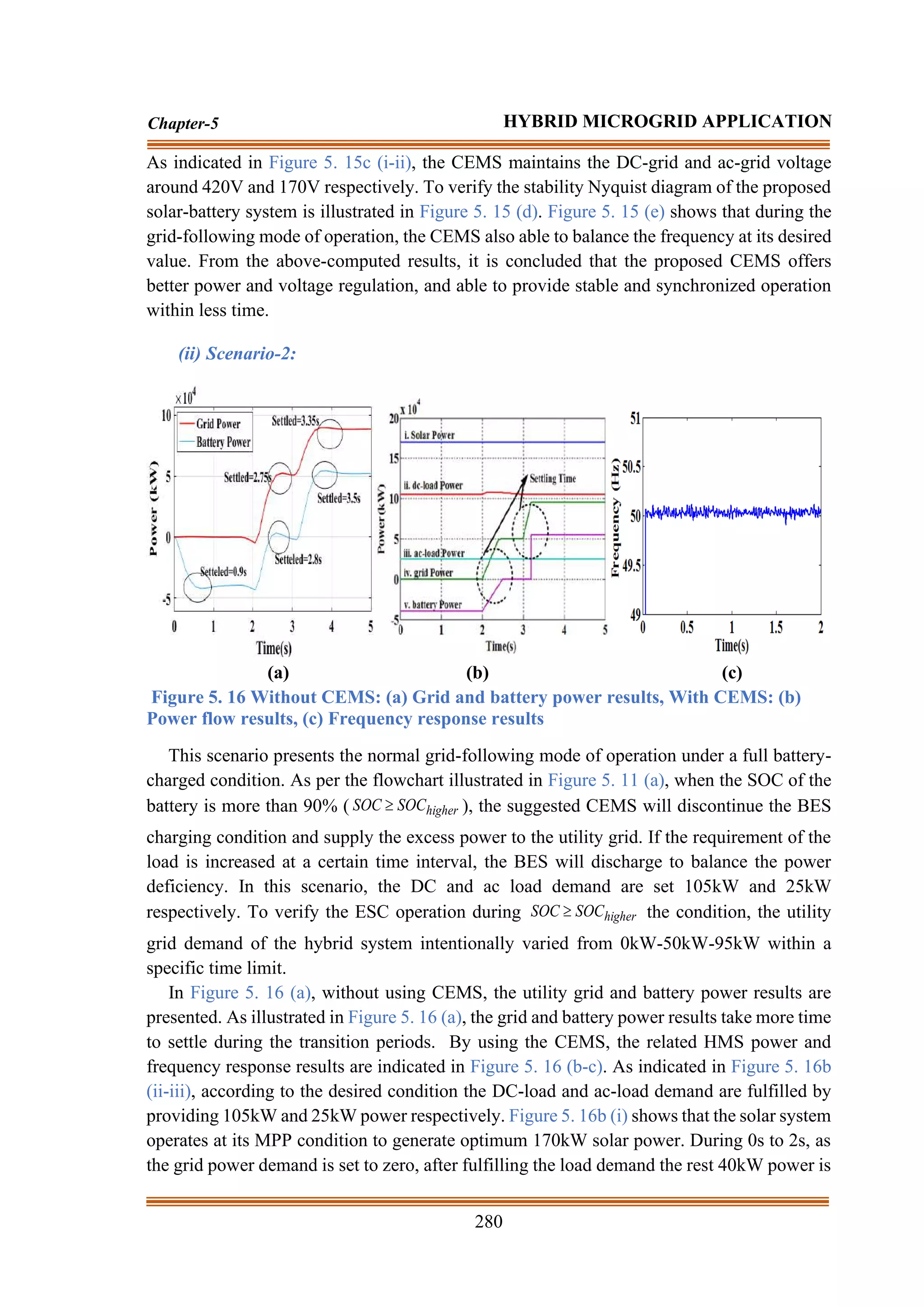
![290
Chapter-5 HYBRID MICROGRID APPLICATION
concluded that the proposed approach results have faster settled as compared to the
traditional approach results. Due to the faster settling responses, the system offers better
synchronization as compared to the traditional absence of CEMS. To show the proposed
approach effectiveness, a comparison between without CEMS and with CEMS based HMS
is presented in Table.5. 2. From Table.5. 2, it is clearly illustrated that the responses of the
proposed approach are a faster settling time according to IEEE-1541 and IEEE 1562-2007
standards [28]. From the results and comparative table, it is concluded that the proposed
HMS achieves better power quality and power reliability by producing linear results and
faster settling time during both normal and transient conditions.
Table.5. 2 Comparative study
Grid following mode Without CEMS With CEMS
Duration Duration
Transition Condition Initial 2.5s 3.2s Initial 2.5s 3.2s
Scenario-1 Grid power 1.1s 2.65s 3.4s 0.1s 2.51s 3.22s
Duration Duration
Transition Condition Initial 2s 3s Initial 2s 3s
Scenario-2 Grid power 0.1s 2.75s 3.35s 0.1s 2.4s 3.2s
Battery power 0.9s 2.8s 3.5s 0.1s 2.4s 3.15s
Duration Duration
Transition Condition Initial 2s 3s Initial 2s 3s
Scenario-3 Solar power 0.82s 2.7s 3.25s 0.1s 2.1s 3.15s
Grid power 0.813s 2.62s 3.22s 0.1s 2.25s 3.16s
Duration Duration
Transition Condition Initial 2s 3s Initial 2s 3s
Scenario-4 Grid power 0.65s 2.7s 3.5s 0.1s 2.5s 3.2s
Transition Condition Duration=2.5s Duration=2.5s
ac-load power 3.3s 3s
Transition Condition Duration=2s Duration=2s
DC-load
power
2.5s 2.23s
Duration Duration
Transition Condition Initial 4s 6.2s Initial 4s 6.2s
Scenario-5 Battery power 0.98s 4.25s 6.5s 0.1s 4.05s 6.21s
Active power 1.1s - - - - -
Reactive
power
0.1s 4.5s 6.35s 0.1s 4.2s 6.23s
Grid forming mode Without CEMS With CEMS
Duration Duration
Transition Condition Initial 1.2s 2.5s Initial 1.2s 2.5s
Scenario-1 Battery power 0.75s 1.5s 2.9s 0.1s 1.21s 2.51s
Transition Condition Duration=2.5s Duration=2.5s
DC-load
power
2.75s 2.52s
Transition Condition Duration=1.2s Duration=1.2s
ac-load power 1.8s 1.56s](https://image.slidesharecdn.com/dr-211204045233/75/Robust-Active-Power-Filter-Controller-Design-for-Microgrid-and-Electric-Vehicle-Applications-part-2-85-2048.jpg)

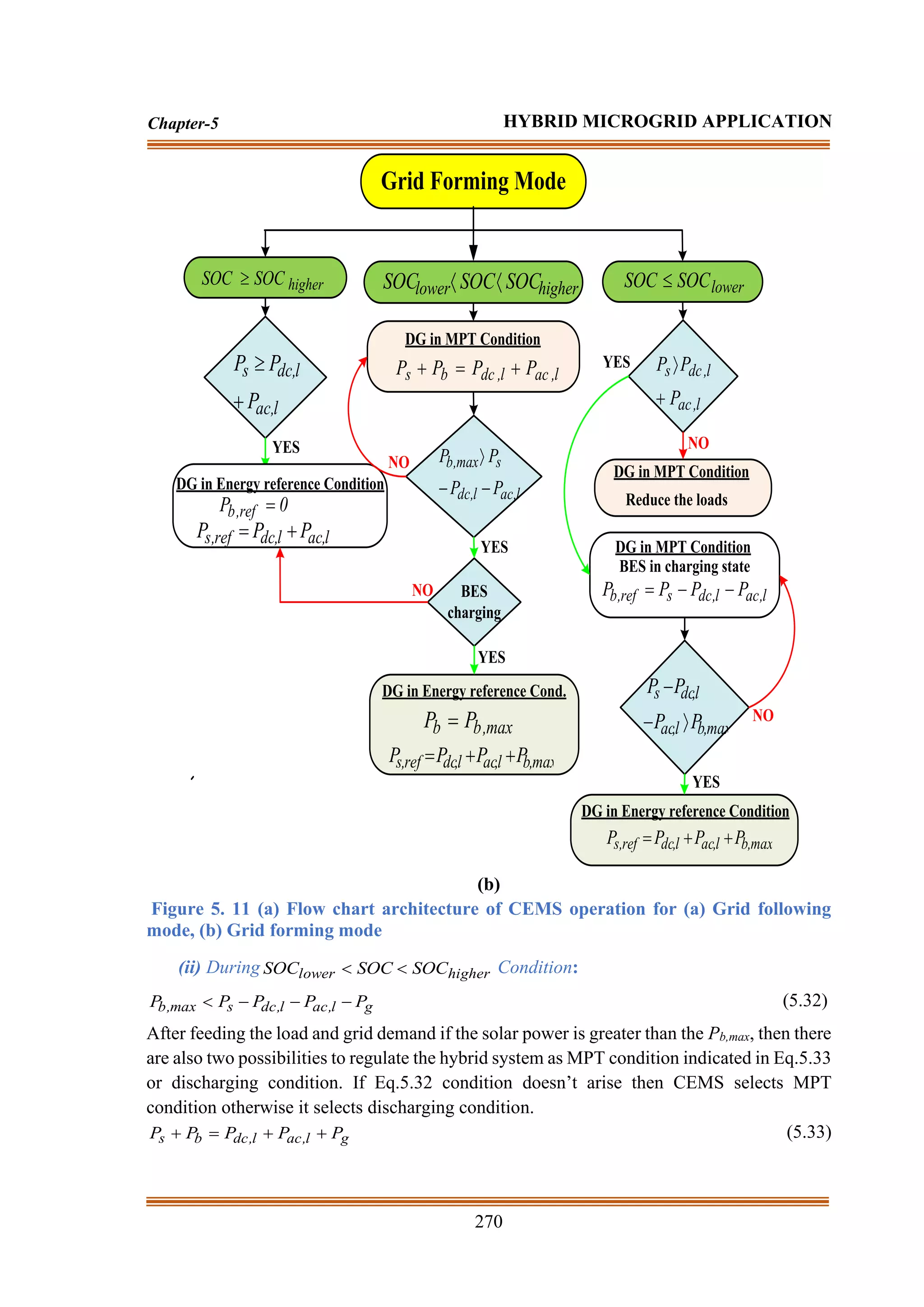
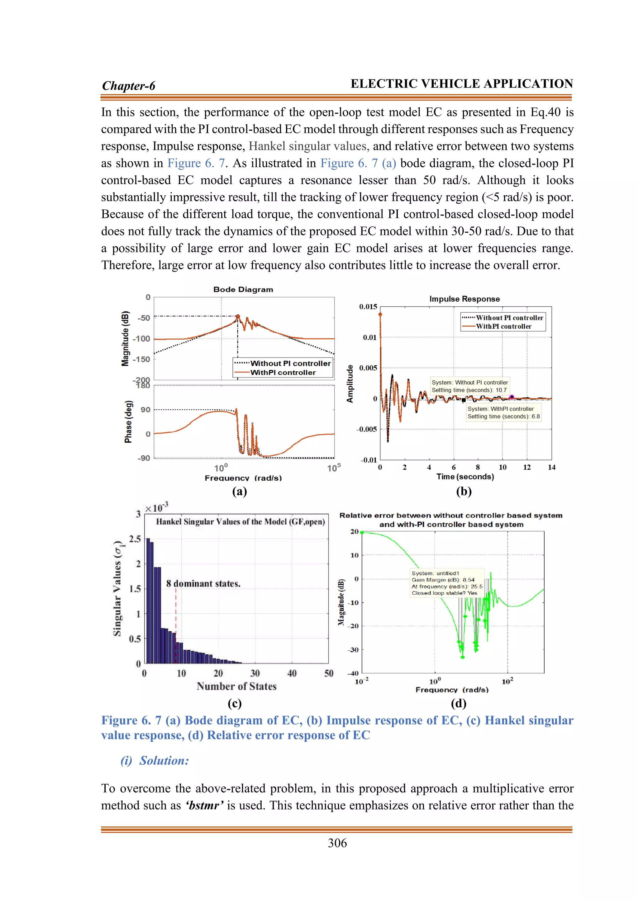
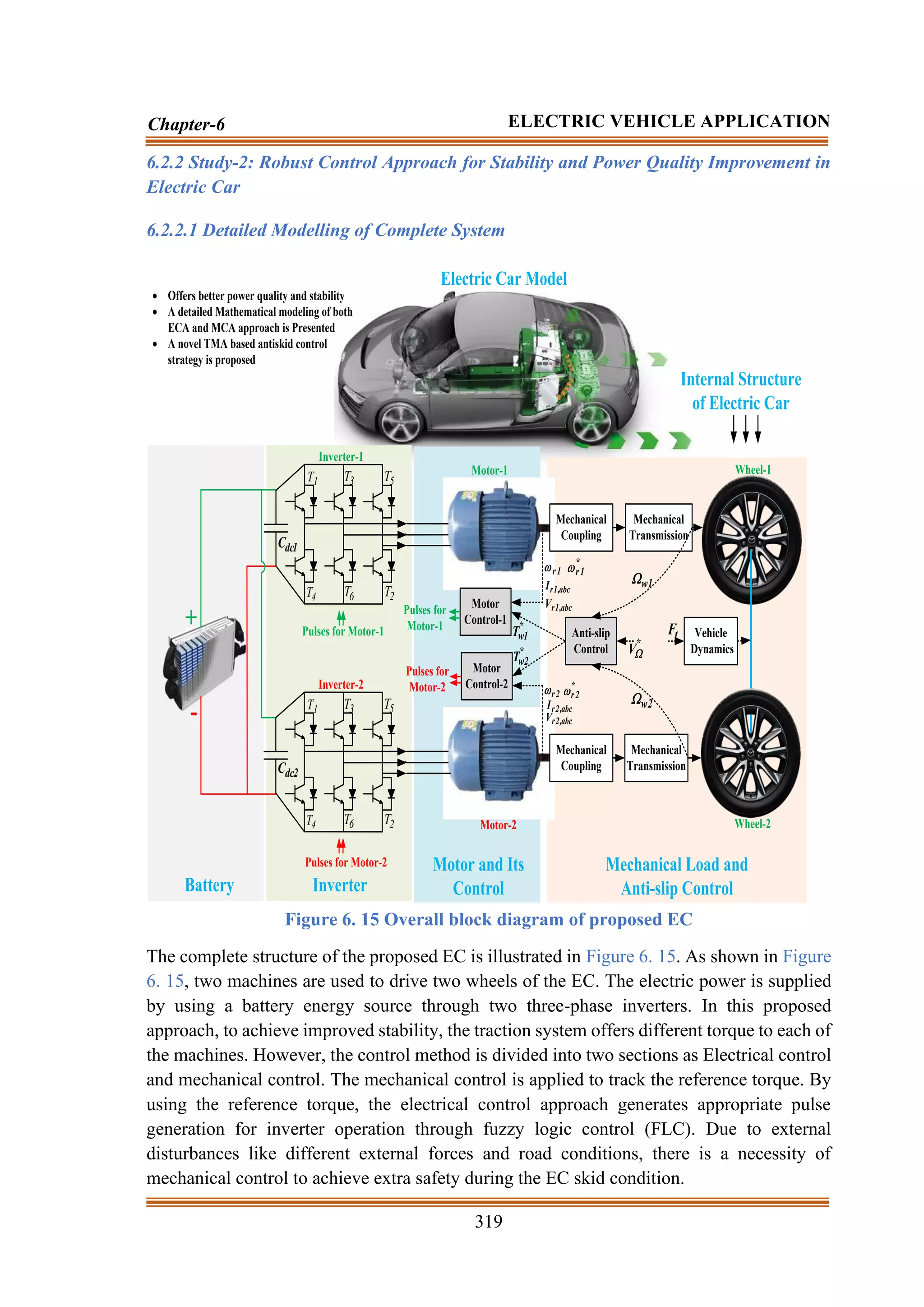
![Chapter-6
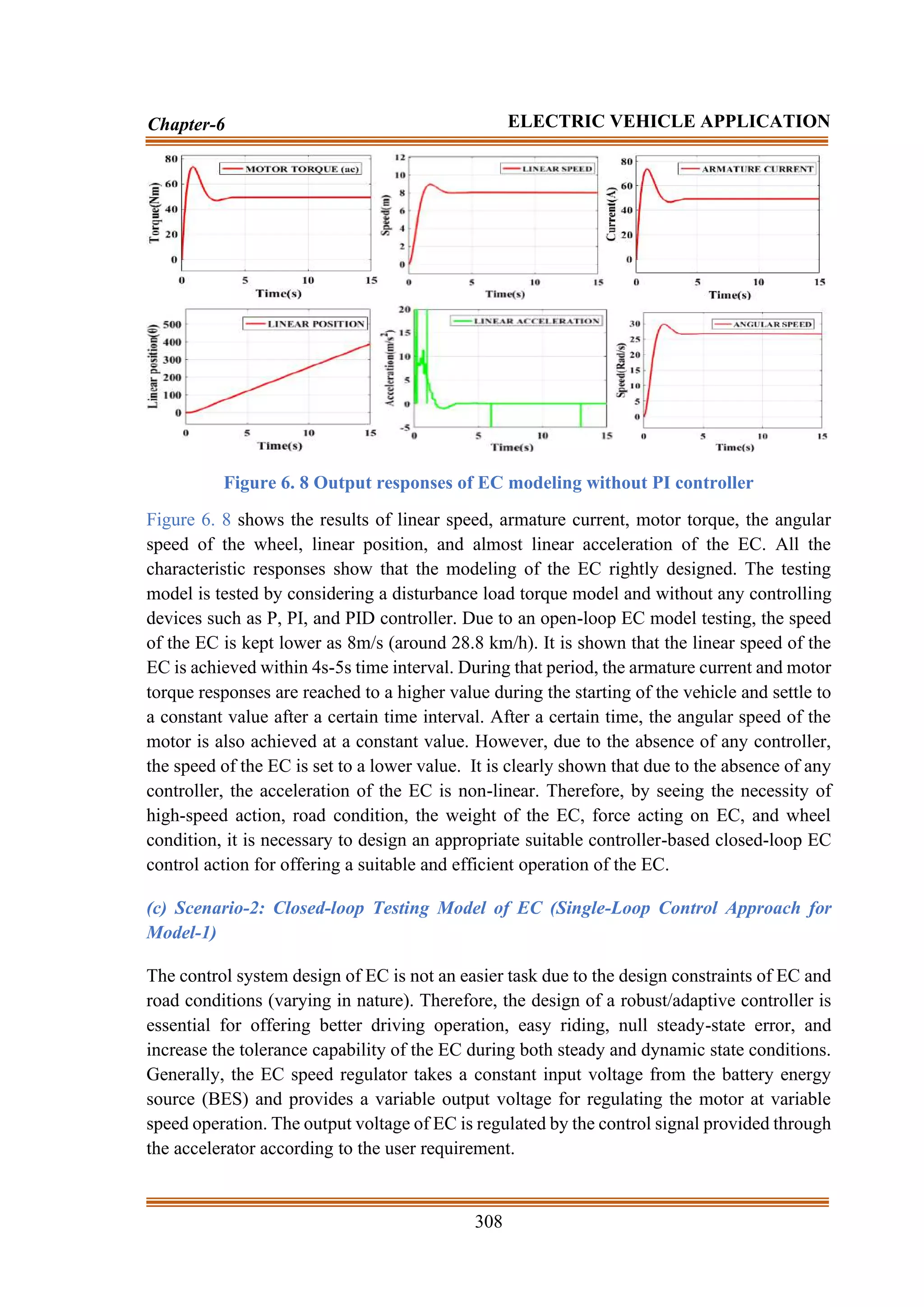
ELECTRIC VEHICLE APPLICATION
6.1 Introduction
Looking at the environmental condition and the awareness of energy conservation,
researchers are paying more attention to the design of zero-polluting ECs. Recently, the
improvement with regards to EC/Hybrid-EC modeling is gaining interest on an augmented
pace [323]. Particularly, the lesser weight ECs are becoming popular in many applications
like patrolling and smaller distance transportation cars. Lots of EC modeling techniques are
suggested to offer a larger driving range and linear operation [324]. Generally, the EC
modeling is designed by considering two subsystems like electric motors (EM) as a drive
system and the car platform as indicated in Fig.1. The main components of EC are battery
energy storage (BES) devices, central control structures, tachometer, and voltage source
converter (VSCs) that convert dc-ac power. To drive the EC wheel, single EM is used for
each of the wheels [325]. However, the increasing cost and complex modeling, [326] lose its
attraction during real-time applications. By viewing the simplicity and easier control action,
dc EM is popularly selected for the traction of ECs [327]. In addition to that dc-motors also
supply high starting torque. Therefore, for availing a robust/lighter model with high
efficiency, and reduced cost EC, it is necessary to derive an appropriate mathematical model
of EC and EM for both steady and dynamic state operations.
Simple EC design leads to a simple control strategy that decreases the overall cost of
the vehicle. However, the development of the simple EC model is difficult because of the
uncertainty and non-linearity present in the environmental, wheel, and road conditions [328-
212]. Mostly, the disturbances are categorized into two types such as (1) parametric non-
linearities and (2) inner/outer disturbances. The first type of disturbance is raised due to the
lack of appropriate information regarding the EC modeling, friction modeling, and parameter
fault conditions, and the second type of disturbance is generated due to the unidentified
effects of existing physical constraints in the environment [329-330]. Therefore, there is a
necessity to design improved mathematical modeling of EC by considering the possible real-
time disturbances.
Normally, the ECs are recognized as ‘MCMM’ [331-332]. Therefore, there is a
necessity to develop a coordinated electrical and mechanical control approach for facilitating
satisfactory driving performance and smoother operation by optimally consuming power](https://image.slidesharecdn.com/dr-211204045233/75/Robust-Active-Power-Filter-Controller-Design-for-Microgrid-and-Electric-Vehicle-Applications-part-2-90-2048.jpg)
![294
Chapter-6 ELECTRIC VEHICLE APPLICATION
[287]. Due to the tremendous growth of the microprocessors/microchips, it is easier to
develop the complex controller for MCMM based EC operation [333]. By using the above
controller, the stability and safety of the EC are significantly improved during different state
conditions [334]. Many researchers have proposed different adaptive techniques to overcome
the first type of problems [335]. However, during the non-linear and disturbance conditions,
the adaptive techniques lag their performance by increasing the torque ripples. As a solution,
different adaptive techniques are proposed to overcome the nonlinearity present in the
environment by increasing the stability and safety of the system [336-338]. In [223], direct
torque control (DTC) for the synchronous machine has gained a lot of attention in the field
of industrial drive application specifically to EC operation. However, due to the excess use
of the hysteresis band controller, the DTC scheme lags their performance by increasing the
torque ripple during the transient condition. In [339], a robust control approach is proposed
to obtain faster ripple-free torque action for eliminating the problems related to the
mechanical transmission of the electrical traction chain. In [340], a novel control technique
for the synchronous machine-based EC wheel is proposed to increase the dynamic DTC
performance and decrease the ripple torque by using a model predictive direct torque control
(MPDTC) with an enhanced cost function during steady-state operation. However, for
MCMS based EC operation, the predictive torque control is not providing a suitable solution
during dynamic state conditions like slippery road conditions. To reduce the ripple torque
problem and disturbance conditions, adaptive feedback linearization approaches are
proposed for guessing an approximate disturbance component [341]. However, the offline
non-linearity identification control techniques are not well suited for MCMS because the
disturbances change over time. Therefore, there is a necessity to develop a suitable online
adaptation technique for generating lesser ripples torque components.
In addition to the above, for improving the EC stability and safety condition, it is
necessary to regulate the electric machines according to the road and wheel position. To
achieve this, there is a requirement for better synchronization between ECA and MCA. For
achieving better synchronization and full utilization of the electric motor application, a
control law is required to formulate. By tracking the appropriate EC speed, the electrical
torque, wheel torque, road condition, and operating time, the control law for the MCMS
system is proposed for accelerating and deaccelerating the EC [342]. For improving the
stability and safety of the EC during slippery road conditions, the formulation of a suitable
control is considered as one of the major aspects of the study.
Furthermore, recently in automotive applications, there is a novel active control
technique used to improvise safety and provide antiskid operation during the EC riding and
handling conditions. Special control techniques are developed and applied for different parts
of the EC applications [343]. One of the special techniques like the traction control technique
(TCA) is a very classic and unique technique used for improving the EC stability and
reliability problem [154]. TCA is a control approach which prevents the skidding of wheels
during slippery road condition [286]. By doing a technical literature survey, it is found that
TCA is alternatively termed as an acceleration slip regulation (ASR) [344]. To design TCA,](https://image.slidesharecdn.com/dr-211204045233/75/Robust-Active-Power-Filter-Controller-Design-for-Microgrid-and-Electric-Vehicle-Applications-part-2-91-2048.jpg)
![295
Chapter-6 ELECTRIC VEHICLE APPLICATION
different control schemes are suggested by many researchers, and few of them are discussed
below.
In [334], a Fuzzy-PI based ASR scheme for appropriate estimation of wheel torque is
proposed. However, the above-proposed technique lags their performance and stability due
to the absence of the antiskid function. As a solution in [345], to improve the stability and
vehicle safety, an FLC based antiskid control technique is suggested. In addition to that, a
sliding mode control-based wheel slip controller is suggested for MCMM [346]. A model
predictive controller is suggested for wheel slip control for four in-wheel machines of EC
[311]. However, the above-proposed technique lags their tracking performance due to the
use of a predictive controller, low pass filters, complex control structures, and excess use of
the hysteresis band controller. Therefore, there is a necessity to develop a simple and robust
controller for providing appropriate breaking operations during slippery road conditions.
Looking at the above problems, this chapter is divided into two individual studies as
Study-1, and Study-2, for the appropriate design and control of the electric car through an
appropriate inverter model and novel control strategy. By using the developed RSMLI and
its control strategy, the proposed electric vehicle is designed and its performances are also
studied at different state conditions. In addition to that, the PQ and PR of the proposed
systems are also studied during external disturbance conditions. The main contribution to the
individual studies is presented as follows.
Study-1: A Novel Speed and Current Control Approach for Dynamic Electric
Car Modelling
Major contribution:
• For designing a lighter weight and reduced cost electric car (EC) system, the detailed
mathematical modeling of EC and electric machine (EM) are developed.
• By viewing the inner and outer uncertainty/disturbances, two load models are
designed. Due to the load model, the system gets an appropriate idea about the real
uncertainty conditions.
• Different subsystem transfer functions of EC components such as the battery,
inverter, and motor model are developed to obtain an appropriate idea of the EC
model.
• Improved control models are designed by using different geometrical methods by
using the sensitivity gain of both current sensors and tachometer.
• For offering linear output and linear EC operation, a combined PI control-based outer
speed and inner current control approach is suggested.
• Looking at the real-time conditions, different EC models are suggested for different
operations and applications.](https://image.slidesharecdn.com/dr-211204045233/75/Robust-Active-Power-Filter-Controller-Design-for-Microgrid-and-Electric-Vehicle-Applications-part-2-92-2048.jpg)

![297
Chapter-6 ELECTRIC VEHICLE APPLICATION
appropriate EC model carefully. By computing the appropriate torque and power model, the
detailed dynamic modeling of respective EM and EC is presented below.
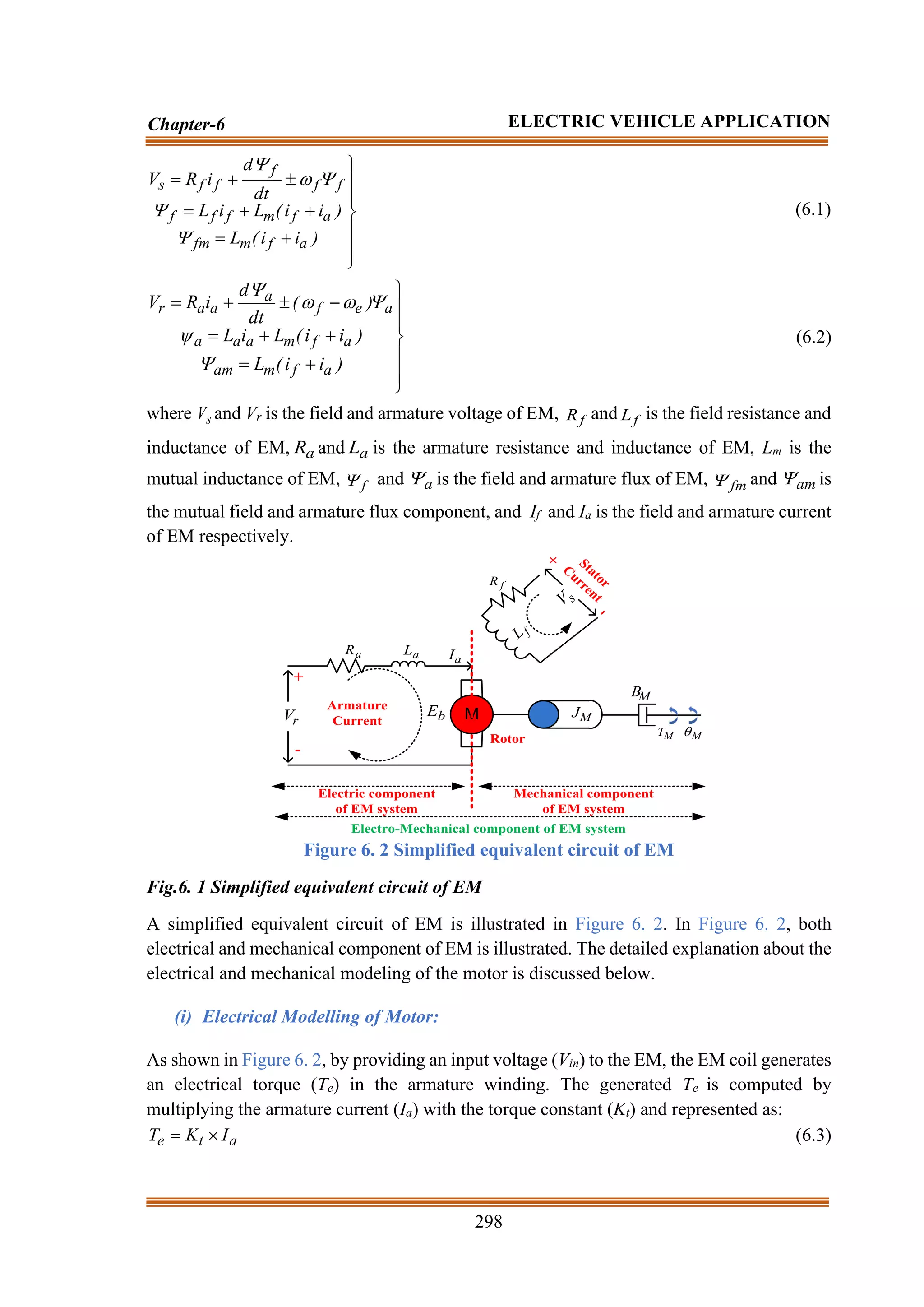
(a) Dynamic Modelling of Electric Motor (DMEM):
The main role of an electric motor (EM) is to provide necessary force for the EC speed
regulation as indicated in Figure 6. 2. Therefore, appropriate mathematical modeling of the
EM is much more important for the EC operation. To assure a suitable speed-up time, the
driving EM necessitates an excess torque output under slower speed and lesser torque output
under higher speed operation. In addition to that, to achieve a higher speed time, driving EM
is necessary to attain a certain power output at high-speed operation [347]. The appropriate
dynamic equation of EM is obtained by combining Newton’s law and Kirchhoff’s law.
Mechanical
Transmission
Mechanical
Coupling
Battery
Charger
Battery Charging point
Controller
Electric
Drivers
DC-AC
Power
inverter
Tachometer
Battery
Front Wheel
AC Motor
Overall diagram of
electric vehicle
Control architecture
of electric vehicle
Figure 6. 1 Complete system architecture of EC
The basic mathematical equations of any EM are presented as follows.](https://image.slidesharecdn.com/dr-211204045233/75/Robust-Active-Power-Filter-Controller-Design-for-Microgrid-and-Electric-Vehicle-Applications-part-2-94-2048.jpg)

![301
Chapter-6 ELECTRIC VEHICLE APPLICATION
n
r
V M
=
(6.25)
Applying Eq.6.25 in Eq.6.23, the JL becomes,
2
2
T
L
n
r
M
J = (6.26)
By considering the above-discussed equations, the equivalent EC open-loop transfer function
( )
s
(
Gs ) can be presented as
b
t
T
T
a
a
t
in
M
s
K
K
)
B
sJ
)(
R
sL
(
n
K
)
s
(
V
)
s
(
)
s
(
G
+
+
+
=
=
(6.27)
By considering the armature voltage input (Vin), the output voltage of the tachometer (Vtach)
with the corresponding load torque (TL), the EC open-loop transfer function ( )
s
(
Go ) can be
presented as.
b
t
a
a
T
T
a
a
tach
t
in
M
tach
in
o
o
K
K
T
)
R
sL
(
)
B
sJ
)(
R
sL
(
K
K
)
s
(
V
)
s
(
K
)
s
(
V
)
s
(
V
)
s
(
G
+
+
+
+
+
=
=
=
(6.28)
where T is denoted as the disturbance torque including the Coulomb friction (TF). To track
the actual speed of the EC and fed it back to the control system, a tachometer is used in EC.
The tachometer dynamics and the corresponding transfer function is illustrated in Eq.6.29.
To achieve a linear speed of EC of 23m/s, the tachometer constant (Ktach) is selected as 0.4696
[28].
)
s
(
K
)
s
(
V
dt
)
t
(
d
K
)
t
(
V M
tach
o
M
tach
o
=
= (6.29)
where o
V is denoted as the system output voltage.
(b) Dynamic Modelling of Electric Car (DMEC):
Force
Resistance
Rolling
FR =
Velocity
Vehicle
VEV =
Force
Wind
FW =
Vehicle
the
of
Force
nal
Gravitatio
Fg =
Force
Inertial
FI =
Force
Traction
FT =
Force
Normal
FN =
angle
driving
=
Figure 6. 3 Free body diagram of EC with different forces
Figure 6. 3 illustrates the overall motion diagram of the electric car by showing different
forces. By balancing the magneto and electromotive force (MMF and EMF) of electric motor
and operating resistive forces [28], the speed of the EC is decided. To derive an accurate](https://image.slidesharecdn.com/dr-211204045233/75/Robust-Active-Power-Filter-Controller-Design-for-Microgrid-and-Electric-Vehicle-Applications-part-2-98-2048.jpg)
![302
Chapter-6 ELECTRIC VEHICLE APPLICATION
DMEC, it is much more important to track the dynamics between the road, wheel condition
and the acting forces such as wind force (FW), inertia force (FI), rolling force (FR), traction
force (FT), and normal force (FN) upon the EC respectively. The EC torque disturbance is the
resultant torque produced by all the resistive forces acting upon the EC as presented below.
acc
_
a
W
R
N
g
I
F
C
2
W
C
F
2
W
C
f
d
W
C
F
r
F
C
C
F
C
F
C
C
T
V
r
J
M
)
V
V
(
A
C
2
1
)
V
V
(
sign
C
.
)
cos(
.
g
.
M
)
V
(
sign
)
sin(
.
g
.
M
V
M
F
+
+
+
+
+
+
+
=
(6.30)
2
a
acc
_
a
r
G
I
F
= (6.31)
where MC is the mass of the car (kg), VC is the velocity of EC (m/s), C
V
is the acceleration
of EC (m/s2
), g is the gravitational force on EC (m/s2
), is the driving angle of EC (rad), Cr
is the rolling coefficient of EC, is the density of air at 20°𝐶 , Cd is the drag coefficient of
EC, Af is the front area of EC, VW is the wind velocity (m/s), JW is the wheel moment of
inertia of EC, r is the radius of the wheel, G is the gear ratio, Ia is the armature current of the
motor, and Fa_acc is the angular acceleration force.
After computing the possible force acting on the EC model, it is necessary to design the
battery model. The battery is used only to provide the supply voltage for the EC operation.
Before computing the battery capacity of the EC, it is necessary to estimate the total
requirement of electrical energy for the EC operation. The power demand is measured in kW
and the power is used to regulate the speed of the EC. The electric power (Pe) is computed
by multiplying the total traction force (FT) and VC, and represented as follows.
C
T
C
e V
F
V
F
P
=
= (6.32)
The battery is the key element for the EC applications. In recent times, many different types
of battery like lead-acid, nickel hydride, and lithium-ion, etc., are used for different purposes
[28]. However, for real-time application point of view, lithium ion-based battery storage
device is selected due to relatively increase in specific energy and power [2-4].
(c) Battery Electric Model:
The equivalent model of the battery is illustrated in Figure 6. 4. As illustrated in Figure 6. 4,
the equivalent battery model is designed by using internal voltage source (Vbi), battery
voltage (Vb), charging and discharging diode (Dbc and Dbd), and charging and discharging
resistance (Rbc, and Rbd) respectively. Db is known as the forward diode of battery and Ib is](https://image.slidesharecdn.com/dr-211204045233/75/Robust-Active-Power-Filter-Controller-Design-for-Microgrid-and-Electric-Vehicle-Applications-part-2-99-2048.jpg)
![303
Chapter-6 ELECTRIC VEHICLE APPLICATION
known as the obtained battery current. The two diodes are generally ideal and only used to
facilitate both charging and discharging operations. The charging currents are denoted as ‘+’
sign and discharging currents are denoted as ‘-’ sign. The rating of Vbi, Rbd, and Rbc depends
upon the depth of battery discharge capability. As indicated in Figure 6. 4 equivalent circuit,
Vb is computed as follows.
−
−
=
0
I
R
V
0
I
R
V
V
b
bc
bi
b
bd
bi
b (6.33)
Internal
Battery
Voltage
Battery
Voltage
+
-
bd
R
bd
D
bc
D bc
R
bi
V
b
V
b
D
b
I
Figure 6. 4 Equivalent battery model
After generating the necessary electric power from the battery (Pe= VC*I) and power
available in the wheel of the EC (Pw), the driving angle ( ) of the EC is computed as follows.
C
C
e
w
V
M
P
P
−
=
(6.34)
After the successful modeling of the battery and DMEC, to get a more accurate precision
about the disturbance force (FD) acting on the EC, some other factors are also taken into
consideration. By viewing the accuracy demand of the EC, different constraints like total
driving resistance force (Fdr) and EC dynamics are considered. For a smooth acceleration of
the EC, the electric motor of the EC is necessary to overcome the Fdr. The modeling of the
EC dynamics is simplified in [286 ,347-348] and the corresponding equations are presented
below. The detailed explanation of the following equations is presented in [311].
2
C
W
d
f
r
C
C
w
D )
V
V
(
r
C
A
2
1
grC
M
)
sin(
g
M
R
)
t
(
F +
+
+
=
(6.35)
r
C
C
2
D C
)
sin(
gr
M
2
1
dt
d
M
r
2
1
)
t
(
T
+
+
= (6.36)
r
C
d
f
2
C
W
C
C
D grC
M
C
A
))
t
(
V
)
t
(
V
(
2
1
)
t
(
V
M
)
t
(
F +
+
+
=
(6.37)
)
cos(
gC
M
C
A
))
t
(
V
)
t
(
V
)(
sin(
g
M
2
1
a
K
M
)
t
(
F r
C
d
f
2
C
W
C
m
C
D
+
+
+
= (6.38)
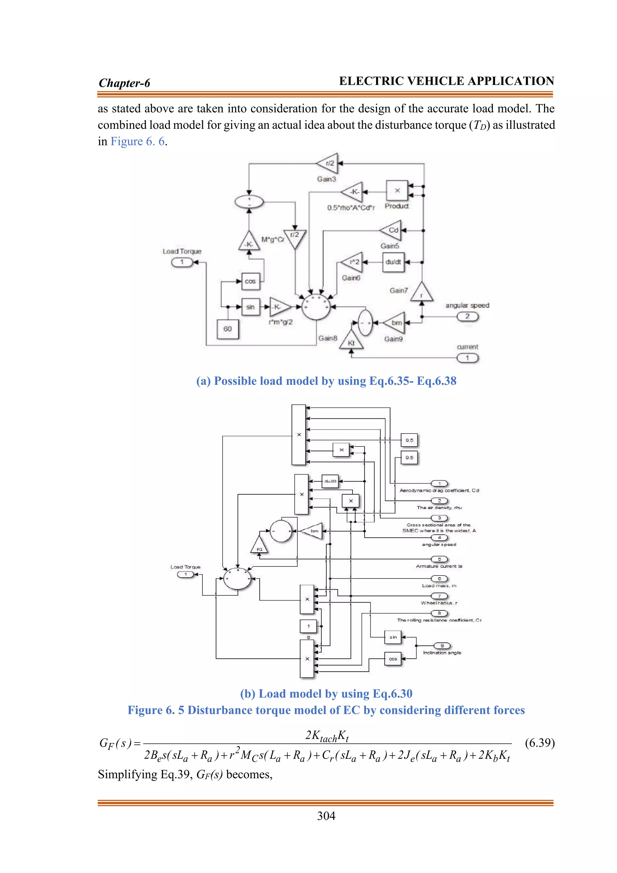
where Rw is the wheel resistance, Km is the equilibrium constant, and ‘a’ is the acceleration
constant of the EC. Based on all the derived dynamic equations as presented in Eq.6.30,
Eq.6.35, Eq.6.36, Eq.6.37, and Eq.6.38, two load models are derived and presented in Figure
6. 5 (a) and Figure 6. 5 (b) respectively. To meet the accuracy level, all the related parameters](https://image.slidesharecdn.com/dr-211204045233/75/Robust-Active-Power-Filter-Controller-Design-for-Microgrid-and-Electric-Vehicle-Applications-part-2-100-2048.jpg)

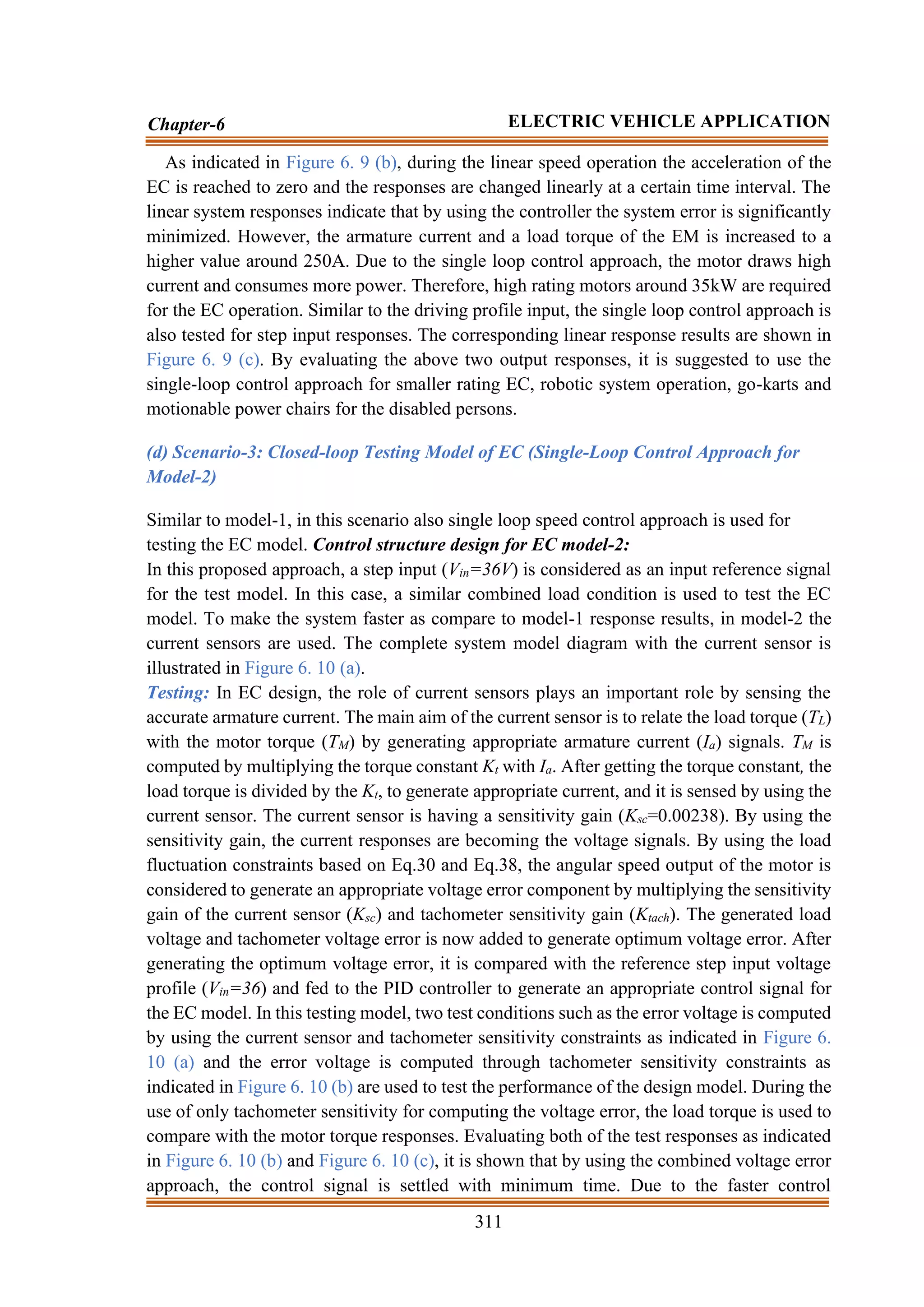
![310
Chapter-6 ELECTRIC VEHICLE APPLICATION
Due to the voltage regulation, the motor speed, as well as EC speed is regulated [349]. During
the operation of the EC accelerator, the battery discharges a specific amount of current to the
EM for achieving the required EC speed. In addition to that, the car sensors sense the actual
speed of the EC and send back it to the controller for offering a closed-loop control action.
As the battery supplies DC voltage and current, inverter plays an important role in dc-ac
voltage and current conversion for EM action. For appropriate voltage regulation, the inverter
switches are necessary to operate through the pulse width modulation (PWM) technique. By
using the PWM technique, the controller sends the required ac power pulses to the EM as a
ratio of thousand times per second. The shorter pulses slow down the motor speed and longer
pulses increase the motor speed. Different control strategies are suggested for the specific
operation of the EC with specific merits and demerits. In this proposed approach, the most
important controllers such as PI, PID, and PI with a deadbeat controller and prefilter is
selected for specific control structure design action.
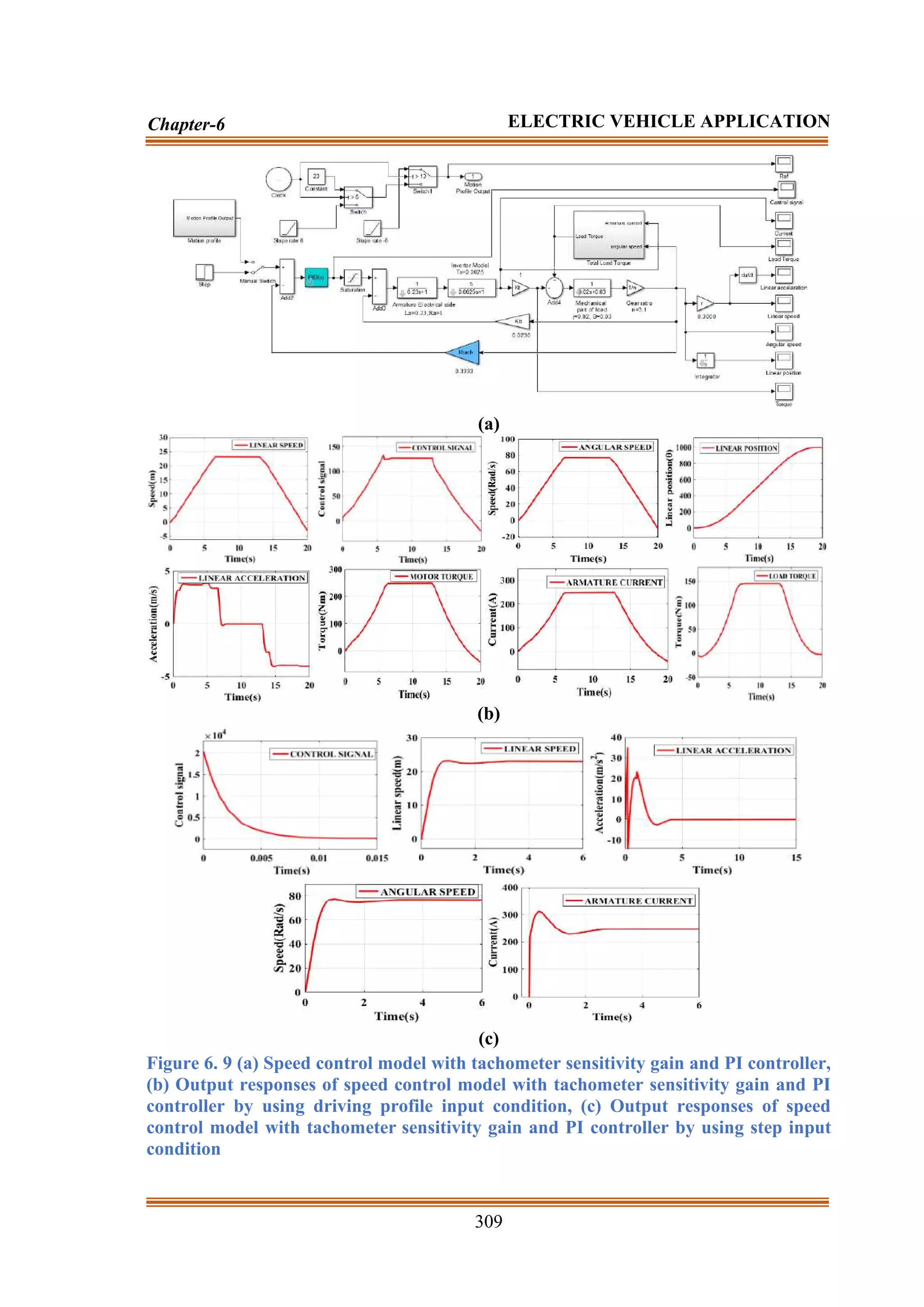
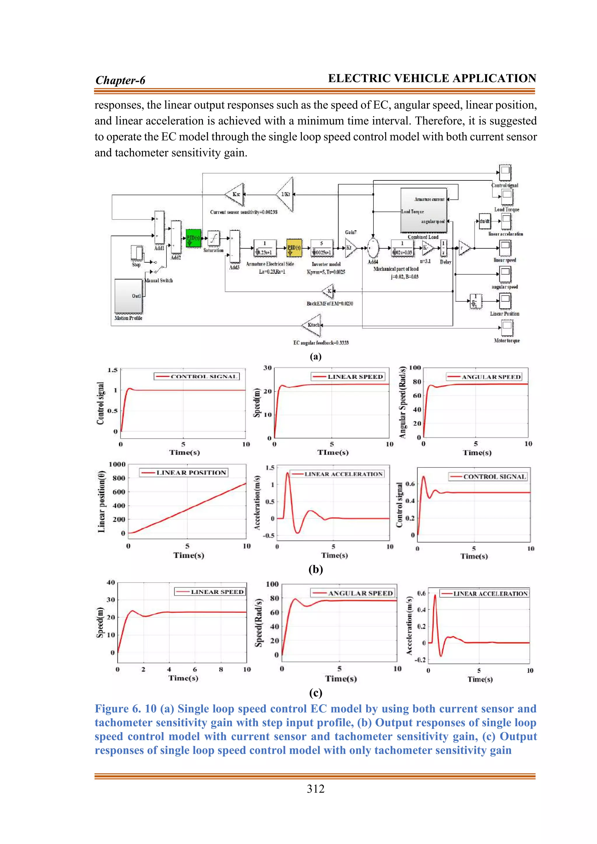
Control structure design for EC (model-1): In this proposed approach, a single PID
regulator-based closed-loop control approach is used to regulate the total EC system. The
total control approach for the EC as illustrated in Figure 6. 9 (a) is known as a speed regulator.
In this test condition, both of the load torque model illustrated in Figure 6. 9 is attached to
the system.
Testing: During the testing of the model, two reference input signals such as step input
(Vin=36) and driving profile input signals are considered. The reference input signals are
manually operated through a manual switch as illustrated in Figure 6. 9 (a). To test the EC
performance, firstly the driving profile is taken as input for the closed-loop EC model. In this
test condition, the most preferred Proportional Integral and Derivative Controller (PIDC) is
selected for controlling the errors generated during the transient condition. Different
strategies like optimization, self-tuning operations, and Zeigler Nicolas are commonly used
to compute the constant parameters. However, during the transient condition, the
computation performances are not well performed [15]. Therefore, in this proposed
approach, the selection of the PID controller parameter is achieved by using the simple
mathematical closed and open-loop time-domain analysis. The detailed explanations to the
constant parameter such as proportional (KP), integral (KI), and derivative (KD) are presented
in [15] by showing the stability criteria of the system. Similar to [15], in this approach, the
Kp, KI, and KD values are computed as 6.734528, 9.652537, and 1.248723 respectively.
In this condition by using the PID controller, the system responses are shown in Figure 6. 9
(b). Figure 6. 9 (b) shows the linear responses of current, speed, torque, and power by
considering the driving profile input. Figure 6. 9 (b) shows that the EC system achieves a
linear speed of 23m/s (approximately 82.8km/h) within 5s-6s time interval. Due to the use
of the PID controller, the linear control output of the PI controller is shown in Figure 6. 9
(b). According to the input condition profile, the angular speed of the motor is computed.
The angular speed of EM is computed around 80 rad/s. By using the computed angular speed,
the linear position of the motor speed is achieved at its desired value. The derivative of the
linear speed generates linear acceleration of the EC.](https://image.slidesharecdn.com/dr-211204045233/75/Robust-Active-Power-Filter-Controller-Design-for-Microgrid-and-Electric-Vehicle-Applications-part-2-107-2048.jpg)
![314
Chapter-6 ELECTRIC VEHICLE APPLICATION
where Kpc is known as the proportional gain (nearer to 1.68), Kic is known as the integral
gain. Tc is denoted as the time constant of the PI regulator (near to 0.08 for faster action).
During the controller design, it is assumed that the proposed inner loop operates faster than
the outer loop. During the controller action, the PIzero (Z0=-Kic/Kpc) factor inversely affects
the system performance. Therefore, to eliminate the Z0 factor a prefilter is used in the SMEC
system. The transfer function of the prefilter ( )
s
(
Gp ) is presented as follows.
1
sT
1
z
s
z
)
s
(
G
c
0
0
p
+
=
+
= (6.43)
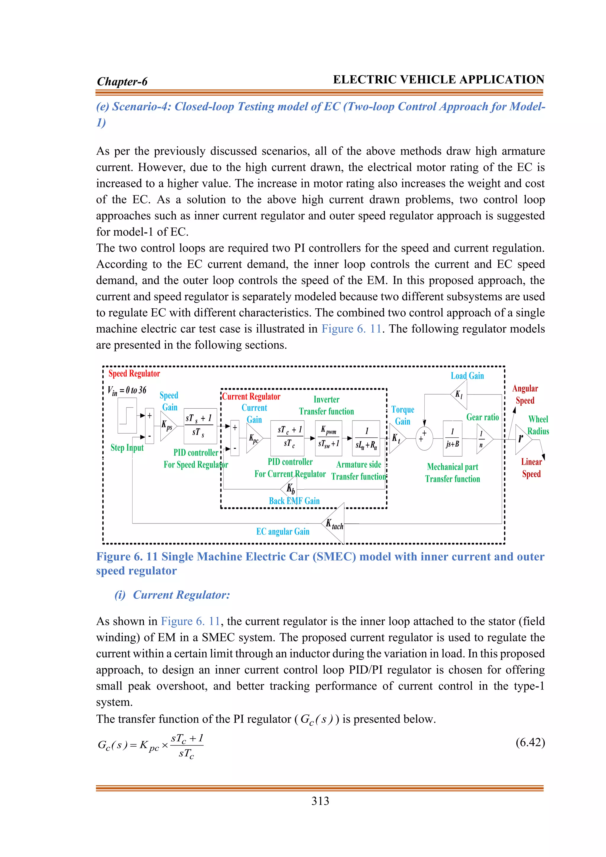
(ii) Speed Regulator:
As shown in Figure 6. 11, the speed regulator is the outer loop of the SMEC model. The
proposed speed regulator loop offers smooth and comfortable riding, zero steady-state error,
and reduces the disturbance during the transient conditions. In this proposed approach, for
achieving a comfortable condition a PID/PI control-based speed regulator is suggested. The
transfer function of the PI regulator for the speed regulator ( )
s
(
Gs ) is presented as follows.
+
=
+
=
+
=
+
=
s
ps
s
s
ps
ps
is
ps
is
ps
s
sT
1
1
K
sT
sT
1
K
s
K
K
s
K
s
K
sK
)
s
(
G (6.44)
where Kps is known as the proportional gain, and Kis is known as the integral gain. Ts is
denoted as the time constant of the PI regulator. The parameters of the PI regulator computed
from the open-loop transfer function is presented as follows.
D
is
D
ps
T
4
J
K
,
T
2
J
K =
= (6.45)
where TD is denoted as the combination of time delay due to the outer loop. In outer loop
condition also the prefilter approach is used to cancel the Z0 factor.
(iii) Inverter Model:
In this approach, the input voltage (Vin) is equal to 36, which is fed to the inverter. The role
of the inverter is to convert the dc voltage to ac voltage. The conversion is dependent upon
the pulse width modulation (PWM) strategy. The output voltage of the system is regulated
through the duty ratio (D) of the PWM signal. The transfer function of the inverter model (
)
s
(
Gi ) and related detailed explanation is presented in [324-326] as shown in Eq.6.46. The
inner loop PI regulator regulates the inverter switching frequency to decrease the ripples in
the motor torque and current in a SMEC system.
1
sT
K
)
s
(
G
sw
pwm
i
+
= (6.46)
where Kpwm is known as the inverter gain (nearer or equal to 5), and Tsw is the switching time
constant of the PWM controller (nearer to 0.25ms).](https://image.slidesharecdn.com/dr-211204045233/75/Robust-Active-Power-Filter-Controller-Design-for-Microgrid-and-Electric-Vehicle-Applications-part-2-111-2048.jpg)


![320
Chapter-6 ELECTRIC VEHICLE APPLICATION
Force
Resistance
External
FR =
Velocity
Car
VC =
Vehicle
the
of
Force
nal
Gravitatio
Fg =
Force
Inertial
FI =
Force
Traction
FT =
Force
Normal
FN =
Surface
Driving
the
of
Angle
=
MMRC
W
V
T
F
C
V
T
F
MMGW
M
RM
T
W
V
T
F
(a) (b) (c)
Force
c
Aerodynami
FA =
MMRC
1
T
F
C
V
MMGW
1
M
1
RM
T
1
W
V
MRMC
MMRC
MMGW
2
M
2
RM
T
2
W
V
C
V
2
T
F
2
T
F
1
T
F
1
M
T
1
M
2
M
2
M
T
EF
C
V
R
F
Mechanical Coupling of EC
** 1 and 2 subscript is used for Machine-1 and
Machine-2 respectively
Machine-1
Machine-2
(d)
Figure 6. 16 Modelling figures (a)MMRC, (b)MMGW, (c) MMFC, (d) Mechanical
coupling of EC
(a) Mechanical Modeling of EC:
The mathematical modeling of EC is presented in the following sections.
(i) Mathematical modeling of road and EC contact (MMRC):
Traction force ( T
F ) between the EC and road is computed as.
F
a
T N
F
= (6.47)
where a
is the adhesive coefficient, and F
N is the normal force acting on EC. The value of
a
is completely dependent upon the slip ‘ ’ and wheel characteristics [333]. is
computed as.](https://image.slidesharecdn.com/dr-211204045233/75/Robust-Active-Power-Filter-Controller-Design-for-Microgrid-and-Electric-Vehicle-Applications-part-2-117-2048.jpg)

![323
Chapter-6 ELECTRIC VEHICLE APPLICATION
r
m cos
I
L
+
= (6.63)
r
m cos
I
L
+
= (6.64)
For the above
/
abc transformation, the slip angle ( s
θ ) is computed as.
r
e
s θ
θ
θ −
= (6.65)
By aligning the
3 rotor current ( abc
,
r
I ) with the
3 rotor voltage ( abc
,
r
V ), through the
phase-locked loop (PLL) the e
θ is computed. The rotor position r
θ is computed through an
encoder. The brushless motor is a non-salient machine and able to generate linear
E .
Therefore, the
L values are equal. For offering smoother operation, reduce the power
losses, sound, vibration, and noise, it is necessary to regulate the current results according to
the linear
E . The generation of linear current responses for inverter action is possible by
computing the proper position of the rotor through
E and proper rotor speed estimation.
The related mathematical modeling is presented in the following section.
The
of the machine is used to compute the angular position of the rotor. Particularly,
during steady-state conditions, the real
vector is synchronized with the rotor and the
position
is the actual rotor position. Still, due to the measurement errors, there is a
possibility of error occurred during the computation of appropriate phase angle and
magnitude of
respectively. The above problem is resolved by using a low pass filter
(LPF) as indicated in Figure 6. 17. The above indecisions are mainly dependent on the
machine speed and it rises during lower frequency motor operation as compared to the LPF
cut-off frequency operation. As a solution, there is a necessity of routine correction for the
correction of errors. However, the routine error correction is not possible during EC
operational conditions. To overcome the possible errors, the following solutions are
necessary to follow.
The
of the machine is computed by integrating the line current and phase voltage of the
machine. The related mathematical expression is presented as follows.
−
=
= dt
)
RI
V
(
dt
E
(6.66)
−
=
= dt
)
RI
V
(
dt
E
(6.67)
By using Eq.6.66 and Eq.6.67, the actual rotor angle ( a
) is computed as.
−
−
= −
LI
LI
tan 1
a (6.68)
By analyzing Eq.6.66 and Eq.6.67, due to the use of pure integrators, the EC suffers from
drift and saturation problems. Meanwhile, the pure integration necessitates an initial
condition at t=0s and the position of the rotor must be known during that period. However,
the possibility of knowing the actual rotor position is not computed during EC operation. As
a solution, to avoid the possibility of error, by using the fact presented in [9] that the position](https://image.slidesharecdn.com/dr-211204045233/75/Robust-Active-Power-Filter-Controller-Design-for-Microgrid-and-Electric-Vehicle-Applications-part-2-120-2048.jpg)

![325
Chapter-6 ELECTRIC VEHICLE APPLICATION
In this proposed approach, the reference speed ( *
r
) of the EC is set to 1750 rpm. By
comparing, the *
r
with the c
speed error e
of the machine is generated. To compute the
linear electrical torque of the machine ( *
r
T ), the e
is passed through an FLC controller.
From the proposed mechanical controller, the mechanical torque (
*
m
T ) is computed. To
generate an appropriate torque error (
*
e
T ), the *
r
T is compared with the
*
m
T respectively. By
using Eq.6.74, the reference reactive current component ( *
r
I ) is computed [339].
dc
C
1
T 3
T
a
a I
,
V
2
T
6
T
4
T
Inverter Motor
b
b I
,
V c
c I
,
V
dc
V
5
T
e
r
+-
s
abc
Cos
_
Sin
abc
abc
V
abc
I
V
V
I
I
R
R
+-
+
-
LPF
LPF
+
+
+
-
+
-
m
1
a
1
a
E
E a
1
−
−
−
LI
LI
tan 1
I
I dt
d
c
+
- *
r
e
FLC
*
r
T
m
p
2
3
2
−
*
r
I
+
-
abc
abc
,
r
I
r
I
e
I
+
-
dc
V
*
dc
V
+
-
p
I
r
I
e
I
Mechanical
Control
+
-
FLC e
,
dc
V
FLC
FLC
I
I
abc
SVPWM
Inverter
Pulses
Selector
abc
I
abc
I
abc
,
r
abc
,
r V
,
I
abc
,
s
abc
,
s V
,
I
r
r
m
s
Inverter Current Controller
2
E
2
E
E
E
*
m
T
*
e
T
Figure 6. 17 Control diagram of proposed ECA
The related mathematical equation is presented as.
*
m
_
r
r
s
m
*
r
e
I
2
p
2
3
)
i
I
(
L
L
2
p
2
3
T
−
=
−
= (6.74)
Similarly, the reference active current component ( p
I ) of the machine is computed by
comparing the reference and actual dc-link voltage (
*
dc
V and dc
V ) of the inverter. By using
−
abc transformation and computed value, the rotor current component is decomposed](https://image.slidesharecdn.com/dr-211204045233/75/Robust-Active-Power-Filter-Controller-Design-for-Microgrid-and-Electric-Vehicle-Applications-part-2-122-2048.jpg)
![326
Chapter-6 ELECTRIC VEHICLE APPLICATION
into the active and reactive current component (
r
I and
r
I ) respectively. The obtained
r
I
and
r
I is compared with the reference p
I and *
r
I current component to generate the
appropriate current error (
e
I and
e
I ) respectively. To linearize
e
I and
e
I , it is passed
through the proposed FLC. The linearized current component (
I and
I ) is transformed
into abc component for generating appropriate switching pulses for the inverter.
Table.6. 1 FLC rules
e
I
Current Error ( e
I )
NB NM NS ZE PS PM PB
NB NB NB NB NM NS ZE PS
NM NB NB NB NM ZE PS PM
NS NB NB NM NS ZE PM PB
ZE NB NM NS ZE PS PM PB
PS NB NM ZE PS PM PB PB
PM NM NS ZE PM PB PB PB
PB NS ZE PS PM PB PB PB
(a) (b) (c)
Figure 6. 18 FLC results: seven linguistic variables based (a) Current input, (b) ∆-
current input, (c) Surface view of FLC
As discussed above, the ECA is used to regulate the current flow by properly regulating the
machine torque and speed through a fuzzy logic controller (FLC). To design the Mamdani
type FLC, the centroid method is used for defuzzification and Gaussian-2 membership
functions are used to design the input and output. Considering two input signals such as
current and ∆-current is used to design the FLC. Each of the input signals contains seven
linguistic variables as negative big (NB), negative medium (NM), negative small (NS), zero
(ZE), positive small (PS), positive medium (PM), and Positive big (PB). By combining two
input signals, to design the FLC 49-rules are selected and presented in Table.6. 1. Similarly,
for speed and dc-link voltage regulation, different
I FLCs are used. The time range of the
inputs is set in between [-10 10] range. As per the requirement, the linguistic variables are](https://image.slidesharecdn.com/dr-211204045233/75/Robust-Active-Power-Filter-Controller-Design-for-Microgrid-and-Electric-Vehicle-Applications-part-2-123-2048.jpg)
![328
Chapter-6 ELECTRIC VEHICLE APPLICATION
• Inversion of MMGW Strategy:
As discussed previously in the MMGW strategy, it is essential to compute the reference speed
and traction force acted upon each of the wheels to achieve maximum control operation for
improving the stability. The linear velocity of the vehicle is achieved by properly regulating
each of the vehicle wheel operations. In this proposed approach, the
*
W
V is computed as.
*
C
*
W
1
V
V
−
= (6.75)
The car velocity is selected as 80km/h. In this proposed approach, during the control
architecture design, the reference slip ( *
) of the vehicle is limited to 10% of the stable slip
and used as the actual antiskid function of the vehicle. The slip selection of the vehicle is
similar to both of the wheels.
(iii) Antiskid Torque Model Architecture (TMA) for Stability Improvement
The proposed TMA is used as an alternative to the robust control method. The major
objective of the proposed TMA is to compute the output of the real plant (process)for
appropriate tracking of the model behavior, through an adaptation method [23-24]. As
illustrated in Figure 6. 19, the adaptation regulator output is directly passing to the process
through the reference input. In the TMA approach, the adaptation method may be a simple
gain or a classical regulator [25]. In this proposed approach, the undertaken real plant model
is a nonlinear system. Therefore, a simple linear regulator is enough to regulate the related
parameters and to assume any operating condition. In this proposed approach a PI controller
is used.
Model
By using the Inverse model
and antiskid control Technique
Adaptation
Process
++
+
-
*
M
T
*
M
T
mod
,
M
M
M
Torque Model Approach
*
m
T
Figure 6. 19 Control diagram of proposed TMA](https://image.slidesharecdn.com/dr-211204045233/75/Robust-Active-Power-Filter-Controller-Design-for-Microgrid-and-Electric-Vehicle-Applications-part-2-125-2048.jpg)
![329
Chapter-6 ELECTRIC VEHICLE APPLICATION
• Design of the behavioural Model:
During the model design, the first priority is to set a behavioural model. In this study, a
mechanical model is selected without considering the slip, which is similar to the interaction
of the wheel and road in the area known as pseudo slip [26]. The developed model is
considered as an ideal model. Moreover, by using the inertia moment of the wheel speed (
Ĵ ) and weight of EC, the total inertia moment ( *
T
J ) of each motor can be computed as.
2
W
g
C
*
T )
R̂
n̂
(
M̂
Ĵ
J +
= (6.76)
MMRC
1
T
F
MMGW
1
M
1
RM
T
1
W
V
MRMC
MMRC
MMGW
2
M
2
RM
T
2
W
V
C
V 2
T
F
2
T
F
1
T
F
1
M
T
1
M
2
M
2
M
T
EF
C
V
R
F
Machine-1
Machine-2
C
V
*
C
V
*
2
T
*
1
T F
F =
*
T
F
*
W
V
Control
MMGW
Inversion
Model
*
M
*
M
T
Model
Model
mod
,
M
,mod
M
T Control
MMGW
,mod
M
T
mod
,
W
V
mod
,
T
F
BMA
mod
,
M
BMA
Proposed
ECA
Proposed
ECA ++
+
+
BMA-2
BMA-1
Process
with
slip
Process
with
slip
Antiskid
Strategy
*
m
T
*
m
T
*
M
T
*
M
T
Figure 6. 20 Control diagram of proposed MCA
The dynamic modeling of the undertaken system becomes,
*
RM
*
M
*
M
*
T T
T
dt
d
J −
=
(6.77)
After developing the dynamic modeling, by considering the slip of the wheel the total
moment of inertia of the system is computed as.
2
W
g
C
T )
R
n
)(
1
(
M
J
J
−
+
= (6.78)](https://image.slidesharecdn.com/dr-211204045233/75/Robust-Active-Power-Filter-Controller-Design-for-Microgrid-and-Electric-Vehicle-Applications-part-2-126-2048.jpg)
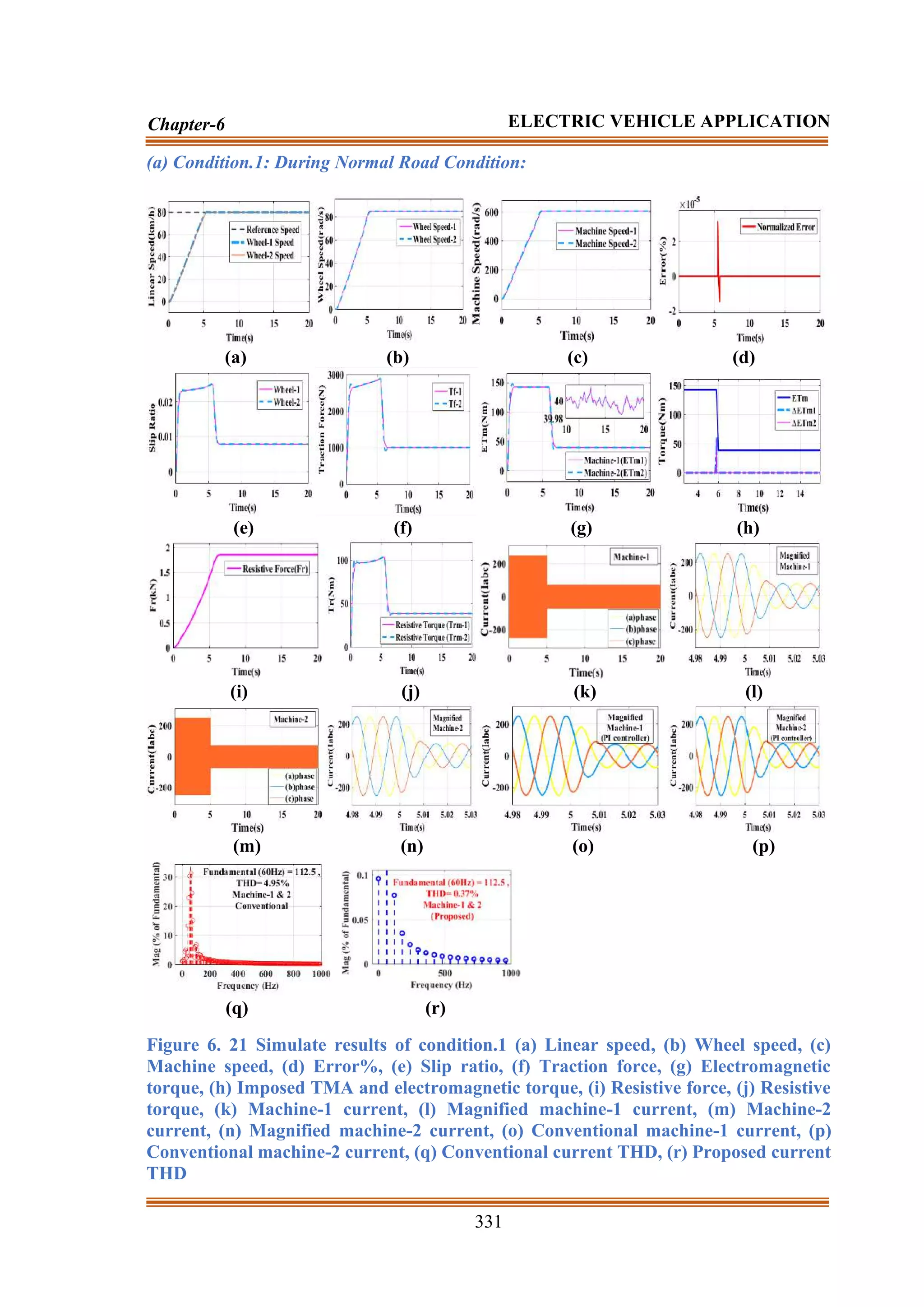

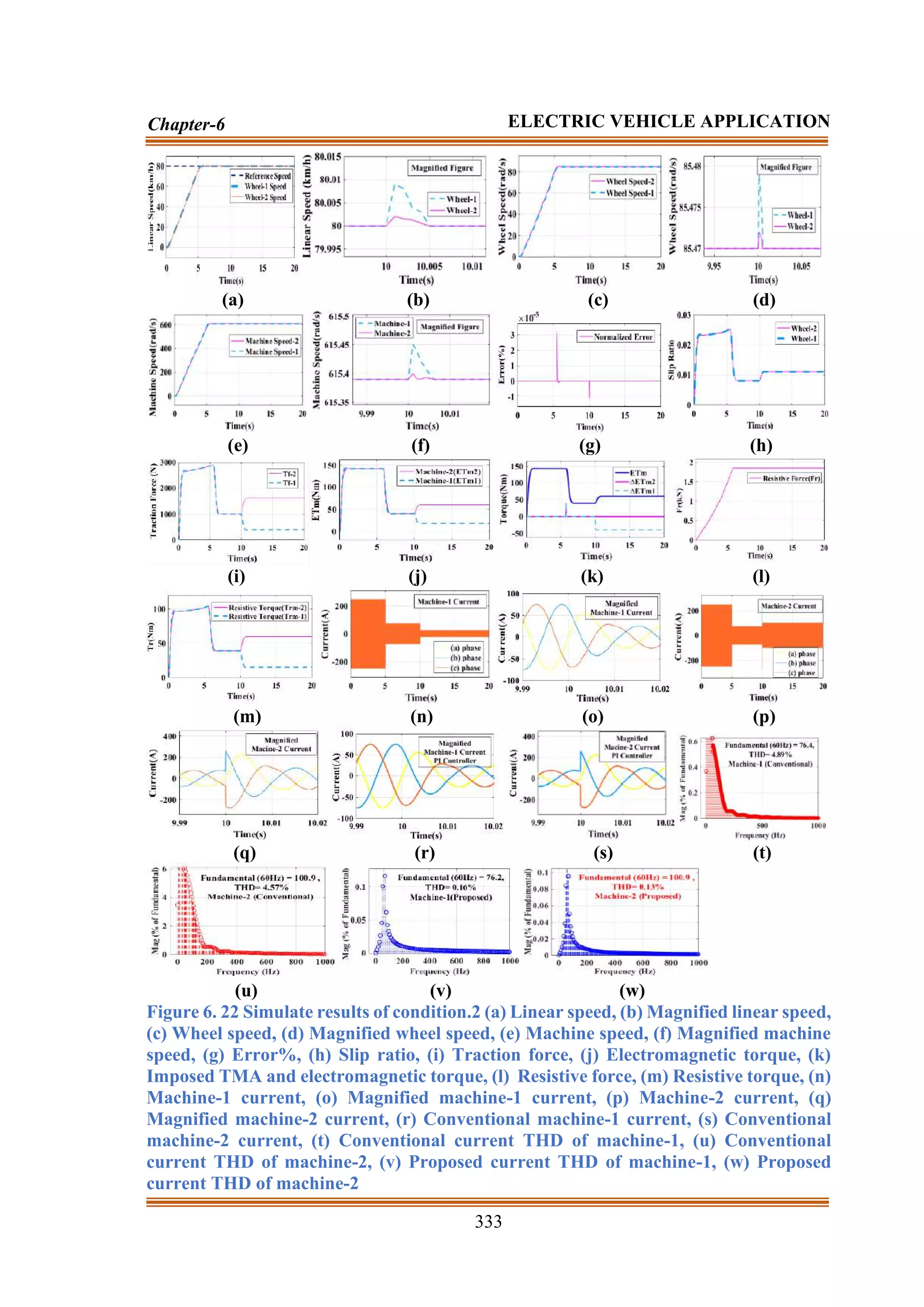
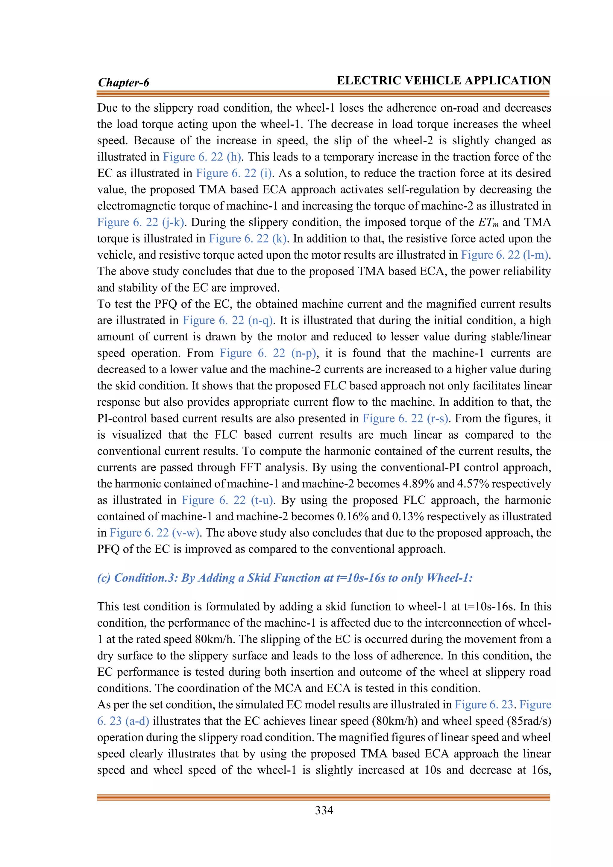

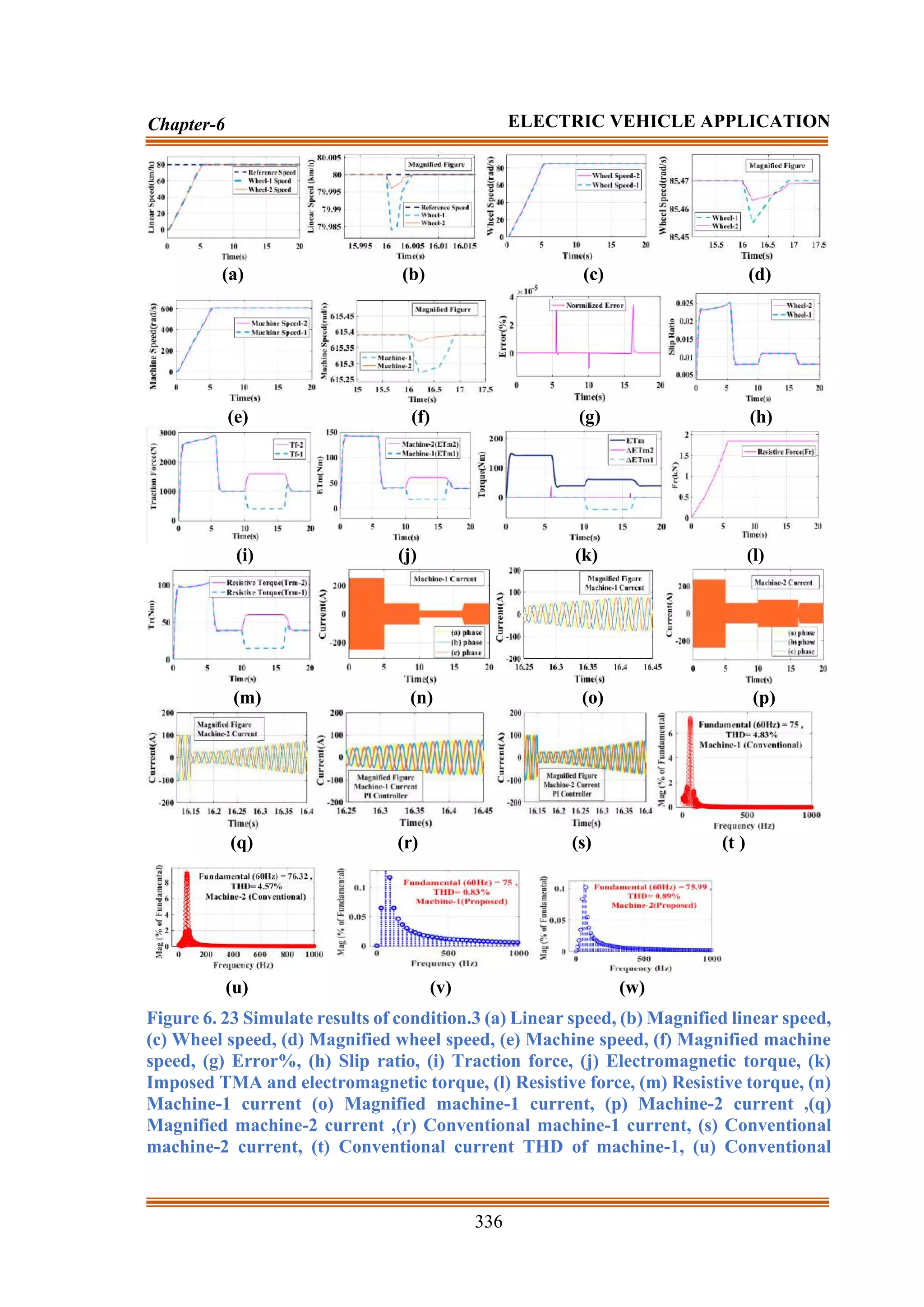

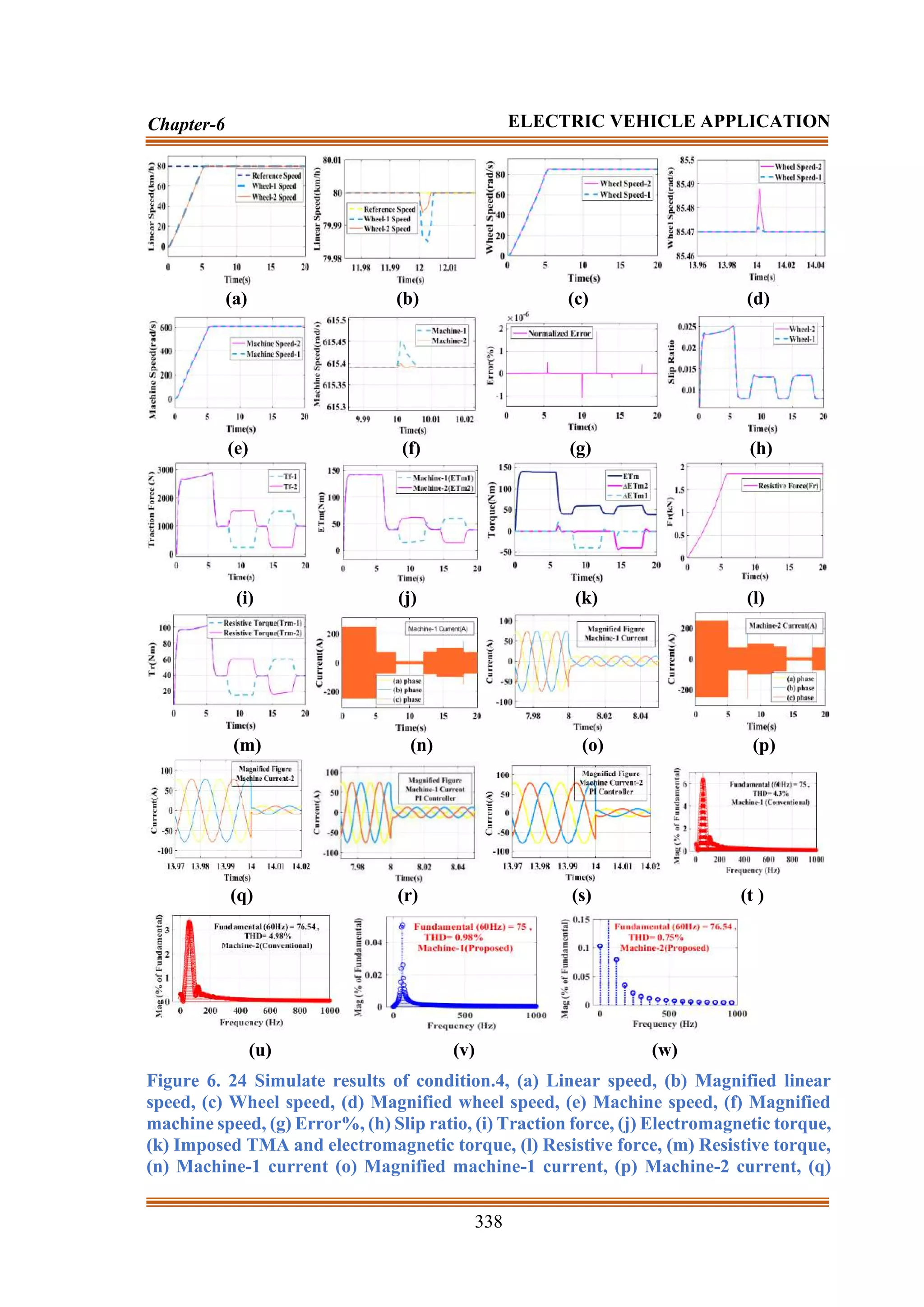


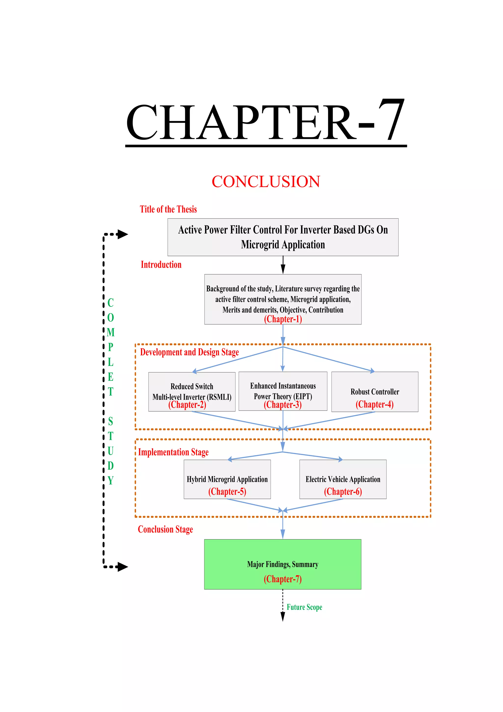


![REFERENCES
[1] Zia, Muhammad Fahad, Elhoussin Elbouchikhi, and Mohamed Benbouzid.
"Microgrids energy management systems: A critical review on methods, solutions,
and prospects." Applied energy 222 (2018): 1033-1055.
[2] Kumar, Dinesh, Firuz Zare, and Arindam Ghosh. "DC microgrid technology: system
architectures, AC grid interfaces, grounding schemes, power quality, communication
networks, applications, and standardizations aspects." Ieee Access 5 (2017): 12230-
12256.
[3] Wu, Pan, et al. "A novel design of architecture and control for multiple microgrids
with hybrid AC/DC connection." Applied Energy 210 (2018): 1002-1016.
[4] Kumar, Mahesh, S. C. Srivastava, and S. N. Singh. "Control strategies of a DC
microgrid for grid connected and islanded operations." IEEE Transactions on Smart
Grid 6.4 (2015): 1588-1601.
[5] Serban, Iona. "A control strategy for microgrids: Seamless transfer based on a leading
inverter with supercapacitor energy storage system." Applied Energy 221 (2018):
490-507.
[6] Cagnano, A., E. De Tuglie, and P. Mancarella. "Microgrids: Overview and guidelines
for practical implementations and operation." Applied Energy 258 (2020): 114039.
[7] Wang, Hao, and Jianwei Huang. "Joint investment and operation of microgrid." IEEE
Transactions on Smart Grid 8.2 (2015): 833-845.
[8] Zenginis, Ioannis, et al. "Cooperation in microgrids through power exchange: An
optimal sizing and operation approach." Applied Energy 203 (2017): 972-981.
[9] Quashie, Mike, et al. "Optimal planning of microgrid power and operating reserve
capacity." Applied Energy 210 (2018): 1229-1236.
[10]Zenginis, Ioannis, et al. "Optimal power equipment sizing and management for
cooperative buildings in microgrids." IEEE Transactions on Industrial Informatics
15.1 (2018): 158-172.
[11]Edge, R., B. York, and N. Enbar. "Rolling out smart inverters: Assessing 1245 utility
strategies and approaches." Power Del. Utilization, Technical Results, Tech. Rep.
3002007047 (2015): 16.
[12]Seal, B., and B. Ealey. "Common functions for smart inverters." EPRI, Knoxville,
TN (2016).
[13]Nejabatkhah, Farzam, Yun Wei Li, and Hao Tian. "Power quality control of smart
hybrid AC/DC microgrids: An overview." IEEE Access 7 (2019): 52295-52318.](https://image.slidesharecdn.com/dr-211204045233/75/Robust-Active-Power-Filter-Controller-Design-for-Microgrid-and-Electric-Vehicle-Applications-part-2-147-2048.jpg)
![349
REFERENCES
[14]Photovoltaics, Distributed Generation, and Energy Storage. "IEEE standard for
interconnection and interoperability of distributed energy resources with associated
electric power systems interfaces." IEEE Std (2018): 1547-2018.
[15]Katiraei, Farid, et al. "Microgrids management." IEEE power and energy magazine
6.3 (2008): 54-65.
[16]Bidram, Ali, and Ali Davoudi. "Hierarchical structure of microgrids control system."
IEEE Transactions on Smart Grid 3.4 (2012): 1963-1976.
[17]Zamora, Ramon, and Anurag K. Srivastava. "Controls for microgrids with storage:
Review, challenges, and research needs." Renewable and Sustainable Energy
Reviews 14.7 (2010): 2009-2018.
[18]Hoevenaars, Eric J., and Curran A. Crawford. "Implications of temporal resolution
for modeling renewables-based power systems." Renewable Energy 41 (2012): 285-
293.
[19]Rikos, Evangelos, et al. "Stability and power quality issues in microgrids under
weather disturbances." IEEE Journal of Selected Topics in Applied Earth
Observations and Remote Sensing 1.3 (2008): 170-179.
[20]Salam, A. A., Azah Mohamed, and M. A. Hannan. "Technical challenges on
microgrids." ARPN Journal of engineering and applied sciences 3.6 (2008): 64-69.
[21]Eghtedarpour, Navid, and Ebrahim Farjah. "Power control and management in a
hybrid AC/DC microgrid." IEEE transactions on smart grid 5.3 (2014): 1494-1505.
[22]Wang, Wei, Rui Li, and J. C. Jiang. "Key issues and research prospects of distribution
system planning orienting to energy internet." High Volt Eng 42.7 (2016): 2028-2036.
[23]Mariam, Lubna, Malabika Basu, and Michael F. Conlon. "Microgrid: Architecture,
policy and future trends." Renewable and Sustainable Energy Reviews 64 (2016):
477-489.
[24]Zhao, Chen, et al. "New problem formulation for optimal demand side response in
hybrid ac/dc systems." IEEE Transactions on Smart Grid 9.4 (2016): 3154-3165.
[25]Lu, Xiaonan, et al. "Hierarchical control of parallel AC-DC converter interfaces for
hybrid microgrids." IEEE Transactions on Smart Grid 5.2 (2013): 683-692
[26]Nejabatkhah, Farzam, and Yun Wei Li. "Overview of power management strategies
of hybrid AC/DC microgrid." IEEE Transactions on Power Electronics 30.12 (2014):
7072-7089.
[27]Unamuno, Eneko, and Jon Andoni Barrena. "Hybrid ac/dc microgrids—Part I:
Review and classification of topologies." Renewable and Sustainable Energy
Reviews 52 (2015): 1251-1259.
[28]Lasseter, Robert H. "Microgrids and distributed generation." Journal of Energy
Engineering 133.3 (2007): 144-149.
[29]Series, I. R. E. "Microgrids and active distribution networks." The institution of
Engineering and Technology (2009).
[30] Micallef, Alexander, et al. "Mitigation of harmonics in grid-connected and islanded
microgrids via virtual admittances and impedances." IEEE Transactions on Smart
Grid 8.2 (2015): 651-661.](https://image.slidesharecdn.com/dr-211204045233/75/Robust-Active-Power-Filter-Controller-Design-for-Microgrid-and-Electric-Vehicle-Applications-part-2-148-2048.jpg)
![350
REFERENCES
[31] Guerrero, Josep M., Lijun Hang, and Javier Uceda. "Control of distributed
uninterruptible power supply systems." IEEE Transactions on Industrial Electronics
55.8 (2008): 2845-2859.
[32] Guerrero, Josep M., et al. "Control strategy for flexible microgrid based on parallel
line-interactive UPS systems." IEEE Transactions on industrial Electronics 56.3
(2008): 726-736.
[33] Yu, Kai, et al. "Analysis and optimization of droop controller for microgrid system
based on small-signal dynamic model." IEEE Transactions on Smart Grid 7.2 (2015):
695-705.
[34] Guerrero, Josep M., et al. "Hierarchical control of droop-controlled AC and DC
microgrids—A general approach toward standardization." IEEE Transactions on
industrial electronics 58.1 (2010): 158-172.
[35] Bidram, Ali, Frank L. Lewis, and Ali Davoudi. "Distributed control systems for
small-scale power networks: Using multiagent cooperative control theory." IEEE
Control Systems Magazine 34.6 (2014): 56-77.
[36] Wang, Xiongfei, et al. "A review of power electronics based microgrids." Journal of
Power Electronics 12.1 (2012): 181-192.
[37] Xu, Xialing, and Xiaoming Zha. "Overview of the researches on distributed
generation and microgrid." 2007 International Power Engineering Conference (IPEC
2007). IEEE, 2007.
[38] Chakraborty, Sudipta, Manoja D. Weiss, and M. Godoy Simoes. "Distributed
intelligent energy management system for a single-phase high-frequency AC
microgrid." IEEE Transactions on Industrial electronics 54.1 (2007): 97-109.
[39] Li, Xiaofei, Xin Ai, and Yonggang Wang. "Study of single-phase HFAC microgrid
based on Matlab/Simulink." 2011 4th International Conference on Electric Utility
Deregulation and Restructuring and Power Technologies (DRPT). IEEE, 2011.
[40] Driesen, Johan, and Farid Katiraei. "Design for distributed energy resources." IEEE
power and energy magazine 6.3 (2008): 30-40.
[41] Kjaer, Soeren Baekhoej, John K. Pedersen, and Frede Blaabjerg. "A review of single-
phase grid-connected inverters for photovoltaic modules." IEEE transactions on
industry applications 41.5 (2005): 1292-1306.
[42] Rahim, N. A., and A. M. Omar. "Three-phase single-stage high-voltage DC
converter." IEE Proceedings-Generation, Transmission and Distribution 149.5
(2002): 505-509.
[43] Ponnaluri, Srinivas, et al. "Comparison of single and two stage topologies for
interface of BESS or fuel cell system using the ABB standard power electronics
building blocks." 2005 European Conference on Power Electronics and
Applications. IEEE, 2005.
[44] Inoue, Shigenori, and Hirofumi Akagi. "A bidirectional isolated DC–DC converter
as a core circuit of the next-generation medium-voltage power conversion system."
IEEE Transactions on Power Electronics 22.2 (2007): 535-542.](https://image.slidesharecdn.com/dr-211204045233/75/Robust-Active-Power-Filter-Controller-Design-for-Microgrid-and-Electric-Vehicle-Applications-part-2-149-2048.jpg)
![351
REFERENCES
[45] Tsikalakis, Antonis G., and Nikos D. Hatziargyriou. "Centralized control for
optimizing microgrids operation." 2011 IEEE power and energy society general
meeting. IEEE, 2011.
[46] Wang, Shih-Ho, and E. J. Davison. "On the stabilization of decentralized control
systems." IEEE Transactions on Automatic Control 18.5 (1973): 473-478.
[47] Hou, Xiaochao, et al. "Distributed hierarchical control of AC microgrid operating in
grid-connected, islanded and their transition modes." Ieee Access 6 (2018): 77388-
77401.
[48] Singh, Harnek, et al. "A Review on Shunt Active Power Filter Control
Strategies." Int. J. Eng. Technol 7 (2018): 121-125.
[49] Chudamani, R., K. Vasudevan, and C. S. Ramalingam. "Non-linear least-squares-
based harmonic estimation algorithm for a shunt active power filter." IET Power
Electronics 2.2 (2009): 134-146.
[50] de Araujo Ribeiro, Ricardo Lúcio, et al. "A robust dc-link voltage control strategy to
enhance the performance of shunt active power filters without harmonic detection
schemes." IEEE Transactions on Industrial Electronics 62.2 (2014): 803-813.
[51] Verdelho, Pedro, and Gil D. Marques. "Four-wire current-regulated PWM voltage
converter." IEEE Transactions on Industrial Electronics 45.5 (1998): 761-770.
[52] Hoon, Yap, et al. "Shunt Active Power Filter: A Review on Phase Synchronization
Control Techniques." Electronics 8.7 (2019): 791.
[53] Baran, Mesut E., and Nikhil R. Mahajan. "Overcurrent protection on voltage-source-
converter-based multiterminal DC distribution systems." IEEE transactions on
power delivery 22.1 (2006): 406-412.
[54] Sainz, Luis, Juan Jose Mesas, and Albert Ferrer. "Characterization of non-linear load
behavior." Electric Power Systems Research 78.10 (2008): 1773-1783.
[55] Wilke, Hans-Joachim, et al. "Thiel-fixation preserves the non-linear load–
deformation characteristic of spinal motion segments, but increases their
flexibility." Journal of the Mechanical Behavior of Biomedical Materials 4.8 (2011):
2133-2137.
[56] Fauri, M. "Harmonic modelling of non-linear load by means of crossed frequency
admittance matrix." IEEE transactions on Power systems 12.4 (1997): 1632-1638.
[57] Santiprapan, P., K. L. Areerak, and K. N. Areerak. "Mathematical model and control
strategy on DQ frame for shunt active power filters." World Academy of Science,
Engineering and Technology 60 (2011): 353-361.
[58] Zhaoan, Yan Xiaoqing Yang Jun Wang. "The Mathematical Model and Stability
Analysis of Shunt Active Power Filter [J]." TRANSACTIONS OF CHINA
ELECTROTECHNICAL SOCIETY 1 (1998).
[59] Mu, Xiaobin, et al. "A modified multifrequency passivity-based control for shunt
active power filter with model-parameter-adaptive capability." IEEE Transactions on
Industrial Electronics 65.1 (2017): 760-769.](https://image.slidesharecdn.com/dr-211204045233/75/Robust-Active-Power-Filter-Controller-Design-for-Microgrid-and-Electric-Vehicle-Applications-part-2-150-2048.jpg)
![352
REFERENCES
[60] Jain, S. K., P. Agrawal, and H. O. Gupta. "Fuzzy logic-controlled shunt active power
filter for power quality improvement." IEE Proceedings-Electric Power
Applications 149.5 (2002): 317-328.
[61] Tao, L., and C. Schwaegerl. "Advanced architectures and control concepts for more
microgrids." EC Project, Tech. Rep. SES6–019864, Tech. Rep. (2009).
[62] Sarkar, Joydeep, and Pramod Yade. "Structuring DC Micro-Grid for Integrating
Renewable Energy in a DC Load Dominant Electrical Environment." International
Journal of Engineering Sciences & Research Technology 3 (2014): 609-613.
[63] Lasseter, Robert H. "Control and design of microgrid components." PSERC
Publication 06-03 (2006).
[64] Li, Yun Wei, and Ching-Nan Kao. "An accurate power control strategy for power-
electronics-interfaced distributed generation units operating in a low-voltage
multibus microgrid." IEEE Transactions on Power Electronics 24.12 (2009): 2977-
2988.
[65] Shuo, Yan, et al. "Electric spring for power quality improvement." 2014 IEEE
Applied Power Electronics Conference and Exposition-APEC 2014. IEEE, 2014.
[66] Shafiee, Qobad, Josep M. Guerrero, and Juan C. Vasquez. "Distributed secondary
control for islanded microgrids—A novel approach." IEEE Transactions on power
electronics 29.2 (2013): 1018-1031.
[67] Wu, Hongying, et al. "A current-mode control technique with instantaneous inductor-
current feedback for UPS inverters." APEC'99. Fourteenth Annual Applied Power
Electronics Conference and Exposition. 1999 Conference Proceedings (Cat. No.
99CH36285). Vol. 2. IEEE, 1999.
[68] Yazdanian, Mehrdad, and Ali Mehrizi-Sani. "Distributed control techniques in
microgrids." IEEE Transactions on Smart Grid 5.6 (2014): 2901-2909.
[69] Blaabjerg, Frede, et al. "Overview of control and grid synchronization for distributed
power generation systems." IEEE Transactions on industrial electronics 53.5 (2006):
1398-1409.
[70] Kazmierkowski, Marian P., and Luigi Malesani. "Current control techniques for
three-phase voltage-source PWM converters: A survey." IEEE Transactions on
industrial electronics 45.5 (1998): 691-703.
[71] Lu, Xiaonan, et al. "An improved droop control method for dc microgrids based on
low bandwidth communication with dc bus voltage restoration and enhanced current
sharing accuracy." IEEE Transactions on Power Electronics 29.4 (2013): 1800-1812.
[72] Lee, Chia-Tse, Chia-Chi Chu, and Po-Tai Cheng. "A new droop control method for
the autonomous operation of distributed energy resource interface converters." IEEE
Transactions on Power Electronics 28.4 (2012): 1980-1993.
[73] Lee, Chia-Tse, Ruei-Pei Jiang, and Po-Tai Cheng. "A grid synchronization method
for droop-controlled distributed energy resource converters." IEEE Transactions on
Industry Applications 49.2 (2013): 954-962.](https://image.slidesharecdn.com/dr-211204045233/75/Robust-Active-Power-Filter-Controller-Design-for-Microgrid-and-Electric-Vehicle-Applications-part-2-151-2048.jpg)
![353
REFERENCES
[74] Majumder, Ritwik, et al. "Angle droop versus frequency droop in a voltage source
converter based autonomous microgrid." 2009 IEEE Power & Energy Society
General Meeting. IEEE, 2009.
[75] Majumder, Ritwik, et al. "Droop control of converter-interfaced micro sources in
rural distributed generation." IEEE Transactions on Power Delivery 25.4 (2010):
2768-2778.
[76] Vasquez, Juan C., et al. "Adaptive droop control applied to voltage-source inverters
operating in grid-connected and islanded modes." IEEE transactions on industrial
electronics 56.10 (2009): 4088-4096.
[77] Li, Yan, and Yun Wei Li. "Power management of inverter interfaced autonomous
microgrid based on virtual frequency-voltage frame." IEEE Transactions on Smart
Grid 2.1 (2011): 30-40.
[78] Hooshmand, Ali, et al. "Stochastic model predictive control method for microgrid
management." 2012 IEEE PES Innovative Smart Grid Technologies (ISGT). IEEE,
2012.
[79] Parisio, Alessandra, and Luigi Glielmo. "Energy efficient microgrid management
using model predictive control." 2011 50th IEEE Conference on Decision and
Control and European Control Conference. IEEE, 2011.
[80] Larrinaga, Sergio Aurtenechea, et al. "Predictive control strategy for DC/AC
converters based on direct power control." IEEE Transactions on Industrial
Electronics 54.3 (2007): 1261-1271.
[81] Parisio, Alessandra, Evangelos Rikos, and Luigi Glielmo. "A model predictive
control approach to microgrid operation optimization." IEEE Transactions on
Control Systems Technology 22.5 (2014): 1813-1827.
[82] Xu, Yinliang, and Wenxin Liu. "Novel multiagent based load restoration algorithm
for microgrids." IEEE Transactions on Smart Grid 2.1 (2011): 152-161
[83] Meng, Lexuan, et al. "Distributed voltage unbalance compensation in islanded
microgrids by using a dynamic consensus algorithm." IEEE Transactions on Power
Electronics 31.1 (2015): 827-838.
[84] Mao, Meiqin, et al. "Multi agent-based hybrid energy management system for
microgrids." IEEE Transactions on Sustainable Energy 5.3 (2014): 938-946.
[85] Logenthiran, Thillainathan, Dipti Srinivasan, and David Wong. "Multi-agent
coordination for DER in MicroGrid." 2008 IEEE International Conference on
Sustainable Energy Technologies. IEEE, 2008.
[86] Dimeas, Aris, and Nikos Hatziargyriou. "A multi-agent system for microgrids."
Hellenic Conference on Artificial Intelligence. Springer, Berlin, Heidelberg, 2004.
[87] Negenborn, Rudy R., Bart De Schutter, and J. Hellendoorn. "Multi-agent model
predictive control: A survey." arXiv preprint arXiv:0908.1076 (2009).
[88] McArthur, Stephen DJ, et al. "Multi-agent systems for power engineering
applications—Part I: Concepts, approaches, and technical challenges." IEEE
Transactions on Power systems 22.4 (2007): 1743-1752.](https://image.slidesharecdn.com/dr-211204045233/75/Robust-Active-Power-Filter-Controller-Design-for-Microgrid-and-Electric-Vehicle-Applications-part-2-152-2048.jpg)
![354
REFERENCES
[89] Luo, Fengji, et al. "Multiagent-based cooperative control framework for microgrids’
energy imbalance." IEEE transactions on industrial informatics 13.3 (2016): 1046-
1056.
[90] Hammerstrom, Donald J. "AC versus DC distribution systemsdid we get it right?."
2007 IEEE Power Engineering Society General Meeting. IEEE, 2007.
[91] Mehrizi-Sani, Ali, and Reza Iravani. "Potential-function based control of a microgrid
in islanded and grid-connected modes." IEEE Transactions on Power Systems 25.4
(2010): 1883-1891.
[92] Sun, Kai, et al. "A distributed control strategy based on DC bus signaling for modular
photovoltaic generation systems with battery energy storage." IEEE Transactions on
Power Electronics 26.10 (2011): 3032-3045.
[93] Anand, Sandeep, Baylon G. Fernandes, and Josep Guerrero. "Distributed control to
ensure proportional load sharing and improve voltage regulation in low-voltage DC
microgrids." IEEE transactions on power electronics 28.4 (2012): 1900-1913.
[94] Liu, Xiong, Peng Wang, and Poh Chiang Loh. "A hybrid AC/DC microgrid and its
coordination control." IEEE Transactions on smart grid 2.2 (2011): 278-286.
[95] Lin, Whei-Min, Chih-Ming Hong, and Chiung-Hsing Chen. "Neural-network-based
MPPT control of a stand-alone hybrid power generation system." IEEE transactions
on power electronics 26.12 (2011): 3571-3581.
[96] Zhou, Tao, and Bruno François. "Energy management and power control of a hybrid
active wind generator for distributed power generation and grid integration." IEEE
transactions on industrial electronics 58.1 (2010): 95-104.
[97] Hamzeh, Mohsen, et al. "Integrating hybrid power source into an islanded MV
microgrid using CHB multilevel inverter under unbalanced and nonlinear load
conditions." IEEE Transactions on energy Conversion 28.3 (2013): 643-651.
[98] Loh, Poh Chiang, et al. "Autonomous operation of hybrid microgrid with AC and DC
subgrids." IEEE transactions on power electronics 28.5 (2012): 2214-2223.
[99] Akhtar, Zohaib, Balarko Chaudhuri, and Shu Yuen Ron Hui. "Smart loads for voltage
control in distribution networks." IEEE Transactions on Smart Grid 8.2 (2015): 937-
946.
[100] Hosseinzadeh, Mehdi, and Farzad Rajaei Salmasi. "Robust optimal power management
system for a hybrid AC/DC micro-grid." IEEE Transactions on Sustainable Energy 6.3
(2015): 675-687.
[101] Han, Junbiao, Sarika Khushalani Solanki, and Jignesh Solanki. "Coordinated
predictive control of a wind/battery microgrid system." IEEE Journal of emerging and
selected topics in power electronics 1.4 (2013): 296-305.
[102] Luna, Adriana C., et al. "Mixed-integer-linear-programming-based energy
management system for hybrid PV-wind-battery microgrids: Modeling, design, and
experimental verification." IEEE Transactions on Power Electronics 32.4 (2016):
2769-2783.](https://image.slidesharecdn.com/dr-211204045233/75/Robust-Active-Power-Filter-Controller-Design-for-Microgrid-and-Electric-Vehicle-Applications-part-2-153-2048.jpg)
![355
REFERENCES
[103] Rokrok, Ebrahim, and Mohamad Esmail Hamedani Golshan. "Adaptive voltage droop
scheme for voltage source converters in an islanded multibus microgrid." IET
generation, transmission & distribution 4.5 (2010): 562-578.
[104] Hui, Shu Yuen, Chi Kwan Lee, and Felix F. Wu. "Electric springs—A new smart grid
technology." IEEE Transactions on Smart Grid 3.3 (2012): 1552-1561.
[105] Sreekumar, Preetha, and Vinod Khadkikar. "A new virtual harmonic impedance
scheme for harmonic power sharing in an islanded microgrid." IEEE Transactions on
Power Delivery 31.3 (2015): 936-945.
[106] Jiang, Zhenhua. "Agent-based control framework for distributed energy resources
microgrids." 2006 IEEE/WIC/ACM International Conference on Intelligent Agent
Technology. IEEE, 2006.
[107] Shadmand, Mohammad B., Robert S. Balog, and Haitham Abu-Rub. "Model predictive
control of PV sources in a smart DC distribution system: Maximum power point
tracking and droop control." IEEE Transactions on Energy Conversion 29.4 (2014):
913-921.
[108] Lopes, JA Peças, C. L. Moreira, and A. G. Madureira. "Defining control strategies for
microgrids islanded operation." IEEE Transactions on power systems 21.2 (2006):
916-924.
[109] Guerrero, Josep M., et al. "Output impedance design of parallel-connected UPS
inverters with wireless load-sharing control." IEEE Transactions on industrial
electronics 52.4 (2005): 1126-1135.
[110] De Brabandere, Karel, et al. "A voltage and frequency droop control method for
parallel inverters." IEEE Transactions on power electronics 22.4 (2007): 1107-1115.
[111] He, Jinwei, et al. "An islanding microgrid power sharing approach using enhanced
virtual impedance control scheme." IEEE Transactions on Power Electronics 28.11
(2013): 5272-5282.
[112] Zhong, Qing-Chang. "Robust droop controller for accurate proportional load sharing
among inverters operated in parallel." IEEE Transactions on Industrial Electronics
60.4 (2011): 1281-1290.
[113] Mohamed, Yasser Abdel-Rady Ibrahim, and Ehab F. El-Saadany. "Adaptive
decentralized droop controller to preserve power sharing stability of paralleled
inverters in distributed generation microgrids." IEEE Transactions on Power
Electronics 23.6 (2008): 2806-2816.
[114] Harris, Fred, and Wade Lowdermilk. "Software defined radio: Part 22 in a series of
tutorials on instrumentation and measurement." IEEE instrumentation & measurement
magazine 13.1 (2010): 23-32.
[115] Hannan, Mahammad A., et al. "State-of-the-art and energy management system of
lithium-ion batteries in electric vehicle applications: Issues and recommendations."
Ieee Access 6 (2018): 19362-19378.
[116] Diaz, Nelson L., et al. "Intelligent distributed generation and storage units for DC
microgrids—A new concept on cooperative control without communications beyond
droop control." IEEE Transactions on Smart Grid 5.5 (2014): 2476-2485.](https://image.slidesharecdn.com/dr-211204045233/75/Robust-Active-Power-Filter-Controller-Design-for-Microgrid-and-Electric-Vehicle-Applications-part-2-154-2048.jpg)
![356
REFERENCES
[117] Schonberger, J., Richard Duke, and Simon D. Round. "DC-bus signaling: A distributed
control strategy for a hybrid renewable nanogrid." IEEE Transactions on Industrial
Electronics 53.5 (2006): 1453-1460.
[118] Abdelaziz, Morad Mohamed Abdelmageed, Hany E. Farag, and Ehab F. El-Saadany.
"Optimum droop parameter settings of islanded microgrids with renewable energy
resources." IEEE Transactions on Sustainable Energy 5.2 (2014): 434-445.
[119] Augustine, Sijo, Mahesh K. Mishra, and N. Lakshminarasamma. "Adaptive droop
control strategy for load sharing and circulating current minimization in low-voltage
standalone DC microgrid." IEEE Transactions on Sustainable Energy 6.1 (2014): 132-
141.
[120] Liu, Chen, et al. "Active identification method for line resistance in DC microgrid
based on single pulse injection." IEEE Transactions on Power Electronics 33.7 (2017):
5561-5564.
[121] Wang, Panbao, et al. "An improved distributed secondary control method for DC
microgrids with enhanced dynamic current sharing performance." IEEE Transactions
on Power Electronics 31.9 (2015): 6658-6673.
[122] Li, Xialin, et al. "Flexible interlinking and coordinated power control of multiple DC
microgrids clusters." IEEE Transactions on Sustainable Energy 9.2 (2017): 904-915.
[123] Tu, Chunming, et al. "Analysis and control of a novel modular-based energy router for
DC microgrid cluster." IEEE Journal of Emerging and Selected Topics in Power
Electronics 7.1 (2018): 331-342.
[124] Teleke, Sercan, et al. "Control strategies for battery energy storage for wind farm
dispatching." IEEE transactions on energy conversion 24.3 (2009): 725-732.
[125] Shafiee, Qobad, et al. "Hierarchical control for multiple DC-microgrids clusters." IEEE
Transactions on Energy Conversion 29.4 (2014): 922-933.
[126] Han, Renke, et al. "Stability analysis of primary plug-and-play and secondary leader-
based controllers for DC microgrid clusters." IEEE Transactions on Power Systems
34.3 (2018): 1780-1800.
[127] Prabhakaran, Prajof, Yogendra Goyal, and Vivek Agarwal. "A novel communication-
based average voltage regulation scheme for a droop-controlled DC microgrid." IEEE
Transactions on Smart Grid 10.2 (2017): 1250-1258.
[128] Dou, Chun-Xia, and Bin Liu. "Multi-agent based hierarchical hybrid control for smart
microgrid." IEEE transactions on smart grid 4.2 (2013): 771-778.
[129] Wang, Bo, et al. "Power system transient stability assessment based on big data and
the core vector machine." IEEE Transactions on Smart Grid 7.5 (2016): 2561-2570.
[130] Ustun, Taha Selim, and Reduan H. Khan. "Multiterminal hybrid protection of
microgrids over wireless communications network." IEEE Transactions on Smart Grid
6.5 (2015): 2493-2500.
[131] Hussain, Akhtar, Van-Hai Bui, and Hak-Man Kim. "Fuzzy logic-based operation of
battery energy storage systems (BESSs) for enhancing the resiliency of hybrid
microgrids." Energies 10.3 (2017): 271.](https://image.slidesharecdn.com/dr-211204045233/75/Robust-Active-Power-Filter-Controller-Design-for-Microgrid-and-Electric-Vehicle-Applications-part-2-155-2048.jpg)
![357
REFERENCES
[132] Yoo, Cheol-Hee, et al. "Intelligent control of battery energy storage for multi-agent
based microgrid energy management." Energies 6.10 (2013): 4956-4979.
[133] Chauhan, Rajeev Kumar, et al. "Design and analysis of PID and fuzzy-PID controller
for voltage control of DC microgrid." 2015 IEEE Innovative Smart Grid Technologies-
Asia (ISGT ASIA). IEEE, 2015.
[134] Lagorse, Jérémy, Marcelo G. Simões, and Abdellatif Miraoui. "A multiagent fuzzy-
logic-based energy management of hybrid systems." IEEE transactions on industry
applications 45.6 (2009): 2123-2129.
[135] Miao, Zhixin, et al. "An SOC-based battery management system for microgrids." Ieee
transactions on smart grid 5.2 (2013): 966-973.
[136] Hussein, Karime Farhood, Ikhlas Abdel-Qader, and Mohammed Khalil Hussain.
"Hybrid fuzzy PID controller for buck-boost converter in solar energy-battery
systems." 2015 IEEE International Conference on Electro/Information Technology
(EIT). IEEE, 2015.
[137] Fossati, Juan P., et al. "Optimal scheduling of a microgrid with a fuzzy logic controlled
storage system." International Journal of Electrical Power & Energy Systems 68
(2015): 61-70.
[138] Eldessouky, Ahmed S., and Hossam A. Gabbar. "Micro Grid stability enhancement
using SVC with fuzzy model reference learning controller algorithm." 2015 IEEE
International Conference on Smart Energy Grid Engineering (SEGE). IEEE, 2015.
[139] Hiyama, Takashi, Walid Hubbi, and Thomas H. Ortmeyer. "Fuzzy logic control
scheme with variable gain for static VAr compensator to enhance power system
stability." IEEE transactions on power systems 14.1 (1999): 186-191.
[140] Badar, Rabiah, and Laiq Khan. "Hybrid NeuroFuzzy B-spline Wavelet based SSSC
control for damping power system oscillations." 2012 15th International Multitopic
Conference (INMIC). IEEE, 2012.
[141] Kouba, Nour EL Yakine, et al. "Load frequency control in multi-area power system
based on fuzzy logic-PID controller." 2015 IEEE International Conference on Smart
Energy Grid Engineering (SEGE). IEEE, 2015.
[142] Tagare, Digambar M. Electricity power generation: the changing dimensions. Vol. 56.
John Wiley & Sons, 2011.
[143] Herbert, GM Joselin, S. Iniyan, and D. Amutha. "A review of technical issues on the
development of wind farms." Renewable and Sustainable Energy Reviews 32 (2014):
619-641.
[144] Munteanu, Iulian, et al. Optimal control of wind energy systems: towards a global
approach. Vol. 22. London: Springer, 2008.
[145] Zin, Abdullah Asuhaimi B. Mohd, et al. "An overview on doubly fed induction
generators′ controls and contributions to wind based electricity generation." Renewable
and Sustainable Energy Reviews 27 (2013): 692-708.
[146] Banos, Raul, et al. "Optimization methods applied to renewable and sustainable
energy: A review." Renewable and sustainable energy reviews 15.4 (2011): 1753-
1766.](https://image.slidesharecdn.com/dr-211204045233/75/Robust-Active-Power-Filter-Controller-Design-for-Microgrid-and-Electric-Vehicle-Applications-part-2-156-2048.jpg)
![358
REFERENCES
[147] Qiao, Wei, and Ronald G. Harley. "Grid connection requirements and solutions for
DFIG wind turbines." 2008 IEEE Energy 2030 Conference. IEEE, 2008.
[148] Muller, Set, M. Deicke, and Rik W. De Doncker. "Doubly fed induction generator
systems for wind turbines." IEEE Industry applications magazine 8.3 (2002): 26-33.
[149] Abdullah, Majid A., et al. "A review of maximum power point tracking algorithms for
wind energy systems." Renewable and sustainable energy reviews 16.5 (2012): 3220-
3227.
[150] Sera, Dezso, et al. "On the perturb-and-observe and incremental conductance MPPT
methods for PV systems." IEEE journal of photovoltaics 3.3 (2013): 1070-1078.
[151] Logeswaran, T., and A. SenthilKumar. "A review of maximum power point tracking
algorithms for photovoltaic systems under uniform and non-uniform
irradiances." Energy Procedia 54 (2014): 228-235.
[152] Toledo, Olga Moraes, Delly Oliveira Filho, and Antônia Sônia Alves Cardoso Diniz.
"Distributed photovoltaic generation and energy storage systems: A
review." Renewable and Sustainable Energy Reviews 14.1 (2010): 506-511.
[153] Salmi, Tarak, et al. "Matlab/simulink based modeling of photovoltaic
cell." International Journal of Renewable Energy Research (IJRER) 2.2 (2012): 213-
218.
[154] Sahoo, Buddhadeva, Sangram Keshari Routray, and Pravat Kumar Rout. "A new
topology with the repetitive controller of a reduced switch seven-level cascaded
inverter for a solar PV-battery based microgrid." Engineering science and technology,
an international journal 21.4 (2018): 639-653.
[155] Villalva, Marcelo Gradella, Jonas Rafael Gazoli, and Ernesto Ruppert Filho.
"Comprehensive approach to modeling and simulation of photovoltaic arrays." IEEE
Transactions on power electronics 24.5 (2009): 1198-1208.
[156] De Soto, Widalys, Sanford A. Klein, and William A. Beckman. "Improvement and
validation of a model for photovoltaic array performance." Solar energy 80.1 (2006):
78-88.
[157] Van Zeghbroeck, Bart. "Principles of semiconductor devices." Colarado University 34
(2004).
[158] Tsai, Huan-Liang, Ci-Siang Tu, and Yi-Jie Su. "Development of generalized
photovoltaic model using MATLAB/SIMULINK." Proceedings of the world congress
on Engineering and computer science. Vol. 2008. 2008.
[159] Koutroulis, Eftichios, Kostas Kalaitzakis, and Nicholas C. Voulgaris. "Development
of a microcontroller-based, photovoltaic maximum power point tracking control
system." IEEE Transactions on power electronics 16.1 (2001): 46-54.
[160] Chen, Yang, and Keyue Ma Smedley. "A cost-effective single-stage inverter with
maximum power point tracking." IEEE transactions on power electronics 19.5 (2004):
1289-1294.
[161] Chaves, Madalena, et al. "New approach in back-to-back m-level diode-clamped
multilevel converter modelling and direct current bus voltages balancing." IET Power
Electronics 3.4 (2010): 578-589.](https://image.slidesharecdn.com/dr-211204045233/75/Robust-Active-Power-Filter-Controller-Design-for-Microgrid-and-Electric-Vehicle-Applications-part-2-157-2048.jpg)
![359
REFERENCES
[162] Jain, Sandeep, and Vivek Agarwal. "Comparison of the performance of maximum
power point tracking schemes applied to single-stage grid-connected photovoltaic
systems." IET Electric Power Applications 1.5 (2007): 753-762.
[163] Abad, Gonzalo, et al. Doubly fed induction machine: modeling and control for wind
energy generation. Vol. 85. John Wiley & Sons, 2011.
[164] Hamouda, Noureddine, et al. "Type-2 fuzzy logic predictive control of a grid connected
wind power systems with integrated active power filter capabilities." Journal of Power
Electronics (JPE) 17.6 (2017): 1587-1599.
[165] Mortezaei, Ali, et al. "Multifunctional control strategy for asymmetrical cascaded H-
bridge inverter in microgrid applications." IEEE Transactions on Industry
Applications 53.2 (2016): 1538-1551.
[166] Pena, Ruben, J. C. Clare, and G. M. Asher. "Doubly fed induction generator using
back-to-back PWM converters and its application to variable-speed wind-energy
generation." IEE Proceedings-Electric power applications 143.3 (1996): 231-241.
[167] Sharma, S., and B. Singh. "Voltage and frequency control of asynchronous generator
for stand-alone wind power generation." IET power Electronics 4.7 (2011): 816-826.
[168] Lin, Xinchun, et al. "A new control strategy to balance neutral-point voltage in three-
level NPC inverter." 8th International Conference on Power Electronics-ECCE Asia.
IEEE, 2011.
[169] Wu, Jinn-Chang, and Chia-Wei Chou. "A solar power generation system with a seven-
level inverter." IEEE transactions on power electronics 29.7 (2013): 3454-3462.
[170] Babaei, Ebrahim, and Seyed Hossein Hosseini. "Charge balance control methods for
asymmetrical cascade multilevel converters." 2007 International Conference on
Electrical Machines and Systems (ICEMS). IEEE, 2007.
[171] Wang, Kui, et al. "Voltage balancing and fluctuation-suppression methods of floating
capacitors in a new modular multilevel converter." IEEE Transactions on Industrial
Electronics 60.5 (2012): 1943-1954.
[172] Ebrahimi, Javad, Ebrahim Babaei, and Goverg B. Gharehpetian. "A new topology of
cascaded multilevel converters with reduced number of components for high-voltage
applications." IEEE Transactions on power electronics 26.11 (2011): 3109-3118.
[173] Manjrekar, Madhav D., and Thomas A. Lipo. "A hybrid multilevel inverter topology
for drive applications." APEC'98 Thirteenth Annual Applied Power Electronics
Conference and Exposition. Vol. 2. IEEE, 1998.
[174] Babaei, Ebrahim, Somayeh Alilu, and Sara Laali. "A new general topology for
cascaded multilevel inverters with reduced number of components based on developed
H-bridge." IEEE Transactions on Industrial Electronics 61.8 (2013): 3932-3939.
[175] Sefa, I., et al. "Fuzzy PI controlled inverter for grid interactive renewable energy
systems." IET Renewable Power Generation 9.7 (2015): 729-738.
[176] Nagarajan, R., et al. "Implementation of PV-based boost converter using PI controller
with PSO algorithm." International Journal of Engineering and Computer Science
(IJECS) 6.3 (2017): 20479-20484.](https://image.slidesharecdn.com/dr-211204045233/75/Robust-Active-Power-Filter-Controller-Design-for-Microgrid-and-Electric-Vehicle-Applications-part-2-158-2048.jpg)
![360
REFERENCES
[177] Steinbuch, Maarten. "Repetitive control for systems with uncertain period-
time." Automatica 38.12 (2002): 2103-2109.
[178] Chen, Sufen, et al. "Optimal design of repetitive controller for harmonic elimination in
PWM voltage source inverters." INTELEC 07-29th International Telecommunications
Energy Conference. IEEE, 2007.
[179] Villalva, Marcelo Gradella, Jonas Rafael Gazoli, and Ernesto Ruppert Filho.
"Modeling and circuit-based simulation of photovoltaic arrays." 2009 Brazilian Power
Electronics Conference. IEEE, 2009.
[180] Wang, Fu Sheng, et al. "Zero-Sequence Circulating Current Reduction for Three-Phase
Three-Level Modular Photovoltaic Grid-Connected System." Applied Mechanics and
Materials. Vol. 339. Trans Tech Publications Ltd, 2013.
[181] Teymour, Hamid R., et al. "Solar PV and battery storage integration using a new
configuration of a three-level NPC inverter with advanced control strategy." IEEE
transactions on energy conversion 29.2 (2014): 354-365.
[182] Pereda, Javier, and Juan Dixon. "High-frequency link: A solution for using only one
DC source in asymmetric cascaded multilevel inverters." IEEE Transactions on
Industrial Electronics 58.9 (2011): 3884-3892.
[183] Chavarria, Javier, et al. "Energy-balance control of PV cascaded multilevel grid-
connected inverters under level-shifted and phase-shifted PWMs." IEEE Transactions
on industrial electronics 60.1 (2012): 98-111.
[184] Rodriguez, Jose, et al. "A survey on neutral-point-clamped inverters." IEEE
transactions on Industrial Electronics 57.7 (2009): 2219-2230.
[185] Reznik, Aleksandr, et al. "$ LCL $ filter design and performance analysis for grid-
interconnected systems." IEEE transactions on industry applications 50.2 (2013):
1225-1232.
[186] Dannehl, Joerg, Marco Liserre, and Friedrich Wilhelm Fuchs. "Filter-based active
damping of voltage source converters with $ LCL $ filter." IEEE Transactions on
Industrial Electronics 58.8 (2010): 3623-3633.
[187] Burusteta, Sendoa, et al. "Capacitor voltage balance limits in a multilevel-converter-
based energy storage system." Proceedings of the 2011 14th European Conference on
Power Electronics and Applications. IEEE, 2011.
[188] Jiang, Shuai, et al. "Grid-connected boost-half-bridge photovoltaic microinverter
system using repetitive current control and maximum power point tracking." IEEE
Transactions on power Electronics 27.11 (2012): 4711-4722.
[189] Boutoubat, M., L. Mokrani, and M. Machmoum. "Control of a wind energy conversion
system equipped by a DFIG for active power generation and power quality
improvement." Renewable Energy 50 (2013): 378-386.
[190] Rivas, Darwin, et al. "A simple control scheme for hybrid active power filter." IEE
Proceedings-Generation, Transmission and Distribution 149.4 (2002): 485-490.
[191] Artigao, Estefania, Andres Honrubia-Escribano, and Emilio Gomez-Lazaro. "Current
signature analysis to monitor DFIG wind turbine generators: A case study." Renewable
Energy 116 (2018): 5-14.](https://image.slidesharecdn.com/dr-211204045233/75/Robust-Active-Power-Filter-Controller-Design-for-Microgrid-and-Electric-Vehicle-Applications-part-2-159-2048.jpg)
![361
REFERENCES
[192] Yang, Yongheng, et al. "Design for reliability of power electronic systems." Power
electronics handbook. Butterworth-Heinemann, 2018. 1423-1440.
[193] Yang, Bo, et al. "Nonlinear maximum power point tracking control and modal analysis
of DFIG based wind turbine." International Journal of Electrical Power & Energy
Systems 74 (2016): 429-436.
[194] Tareen, Wajahat Ullah, et al. "Active power filter (APF) for mitigation of power quality
issues in grid integration of wind and photovoltaic energy conversion
system." Renewable and Sustainable Energy Reviews 70 (2017): 635-655.
[195] Khalid, S., and Bharti Dwivedi. "Power quality issues, problems, standards & their
effects in industry with corrective means." International Journal of Advances in
Engineering & Technology 1.2 (2011): 1.
[196] Zobaa, Ahmed F., Shady Aleem, and Murat Erhan Balci, eds. Power System
Harmonics: Analysis, Effects and Mitigation Solutions for Power Quality
Improvement. BoD–Books on Demand, 2018.
[197] Henderson, Robert D., and Patrick J. Rose. "Harmonics: the effects on power quality
and transformers." IEEE transactions on industry applications 30.3 (1994): 528-532.
[198] Swain, Sushree Diptimayee, Pravat Kumar Ray, and Kanungo Barada Mohanty.
"Improvement of power quality using a robust hybrid series active power filter." IEEE
Transactions on Power Electronics 32.5 (2016): 3490-3498.
[199] Dey, Papan, and Saad Mekhilef. "Current controllers of active power filter for power
quality improvement: A technical analysis." automatika 56.1 (2015): 42-54.
[200] Lei, Yazhou, et al. "Modeling of the wind turbine with a doubly fed induction generator
for grid integration studies." IEEE transactions on energy conversion 21.1 (2006):
257-264.
[201] Polinder, Henk, et al. "Comparison of direct-drive and geared generator concepts for
wind turbines." IEEE Transactions on energy conversion 21.3 (2006): 725-733.
[202] Huber, Jonas E., and Johann W. Kolar. "Volume/weight/cost comparison of a 1MVA
10 kV/400 V solid-state against a conventional low-frequency distribution
transformer." 2014 IEEE Energy Conversion Congress and Exposition (ECCE). IEEE,
2014.
[203] Trujillo, D. M. "ANALYSIS AND DESIGN." The Shock and Vibration Digest: A
Publication of the Shock and Vibration Information Center, Naval Research
Laboratory 14.7-12 (1982): 106.
[204] She, Xu, Alex Q. Huang, and Rolando Burgos. "Review of solid-state transformer
technologies and their application in power distribution systems." IEEE journal of
emerging and selected topics in power electronics 1.3 (2013): 186-198.
[205] She, Xu, et al. "Design and demonstration of a 3.6-kV–120-V/10-kVA solid-state
transformer for smart grid application." IEEE Transactions on Power Electronics 29.8
(2013): 3982-3996.
[206] She, Xu, et al. "Wind energy system with integrated functions of active power transfer,
reactive power compensation, and voltage conversion." IEEE Transactions on
Industrial Electronics 60.10 (2012): 4512-4524.](https://image.slidesharecdn.com/dr-211204045233/75/Robust-Active-Power-Filter-Controller-Design-for-Microgrid-and-Electric-Vehicle-Applications-part-2-160-2048.jpg)
![362
REFERENCES
[207] Tsili, Marina, and S. Papathanassiou. "A review of grid code technical requirements
for wind farms." IET Renewable power generation 3.3 (2009): 308-332.
[208] Singh, Bharat, and S. N. Singh. "Wind power interconnection into the power system:
A review of grid code requirements." The Electricity Journal 22.5 (2009): 54-63.
[209] Rodriguez, Jose, Jih-Sheng Lai, and Fang Zheng Peng. "Multilevel inverters: a survey
of topologies, controls, and applications." IEEE Transactions on industrial
electronics 49.4 (2002): 724-738.
[210] Soto, Diego, and Tim C. Green. "A comparison of high-power converter topologies for
the implementation of FACTS controllers." IEEE transactions on industrial
electronics 49.5 (2002): 1072-1080.
[211] Massoud, Ahmed M., et al. "Three-phase, three-wire, five-level cascaded shunt active
filter for power conditioning, using two different space vector modulation
techniques." IEEE Transactions on power delivery 22.4 (2007): 2349-2361.
[212] Sahoo, Buddhadeva, Sangram Keshari Routray, and Pravat Kumar Rout. "Repetitive
control and cascaded multilevel inverter with integrated hybrid active filter capability
for wind energy conversion system." Engineering Science and Technology, an
International Journal 22.3 (2019): 811-826.
[213] Bhattacharya, Avik, and Chandan Chakraborty. "A shunt active power filter with
enhanced performance using ANN-based predictive and adaptive controllers." IEEE
transactions on industrial electronics 58.2 (2010): 421-428.
[214] Eskandarian, Nasser, Yousef Alinejad Beromi, and Shahrokh Farhangi. "Improvement
of dynamic behavior of shunt active power filter using fuzzy instantaneous power
theory." Journal of power Electronics 14.6 (2014): 1303-1313.
[215] Monfared, Mohammad, Saeed Golestan, and Josep M. Guerrero. "A new synchronous
reference frame-based method for single-phase shunt active power filters." Journal of
power Electronics 13.4 (2013): 692-700.
[216] Hoon, Yap, et al. "A dual-function instantaneous power theory for operation of three-
level neutral-point-clamped inverter-based shunt active power filter." Energies 11.6
(2018): 1592.
[217] Sujitjorn, S., K-L. Areerak, and T. Kulworawanichpong. "The DQ axis with fourier
(DQF) method for harmonic identification." IEEE Transactions on Power
Delivery 22.1 (2006): 737-739.
[218] Vodyakho, Oleg, and Chris C. Mi. "Three-level inverter-based shunt active power filter
in three-phase three-wire and four-wire systems." IEEE transactions on power
electronics 24.5 (2009): 1350-1363.
[219] Chen, C. Lin, Chin-E. Lin, and C. L. Huang. "Reactive and harmonic current
compensation for unbalanced three-phase systems using the synchronous detection
method." Electric power systems research 26.3 (1993): 163-170.
[220] Bhuvaneswari, G., Manjula G. Nair, and Sathish Kumar Reddy. "Comparison of
Synchronous Detection and I. Cosϕ Shunt Active Filtering Algorithms." 2006
International Conference on Power Electronic, Drives and Energy Systems. IEEE,
2006.](https://image.slidesharecdn.com/dr-211204045233/75/Robust-Active-Power-Filter-Controller-Design-for-Microgrid-and-Electric-Vehicle-Applications-part-2-161-2048.jpg)
![363
REFERENCES
[221] Forghani, Mehdi, and Saeed Afsharnia. "Online wavelet transform-based control
strategy for UPQC control system." IEEE transactions on power delivery 22.1 (2006):
481-491.
[222] Radzi, Mohd Amran Mohd, and Nasrudin Abd Rahim. "Neural network and bandless
hysteresis approach to control switched capacitor active power filter for reduction of
harmonics." IEEE Transactions on Industrial Electronics 56.5 (2009): 1477-1484.
[223] Sahoo, Buddhadeva, Sangram Keshari Routray, and Pravat Kumar Rout. "Artificial
neural network-based PI-controlled reduced switch cascaded multilevel inverter
operation in wind energy conversion system with solid-state transformer." Iranian
Journal of Science and Technology, Transactions of Electrical Engineering 43.4
(2019): 1053-1073.
[224] Prabaharan, Natarajan, and Kaliannan Palanisamy. "Comparative analysis of
symmetric and asymmetric reduced switch MLI topologies using unipolar pulse width
modulation strategies." IET Power Electronics 9.15 (2016): 2808-2823.
[225] Biricik, Samet, et al. "Real-time control of shunt active power filter under distorted
grid voltage and unbalanced load condition using self-tuning filter." IET Power
Electronics 7.7 (2014): 1895-1905.
[226] Peng, Fang Zheng, and Jih-Sheng Lai. "Generalized instantaneous reactive power
theory for three-phase power systems." IEEE transactions on instrumentation and
measurement 45.1 (1996): 293-297.
[227] Akagi, Hirofumi, Yoshihira Kanazawa, and Akira Nabae. "Instantaneous reactive
power compensators comprising switching devices without energy storage
components." IEEE Transactions on industry applications 3 (1984): 625-630.
[228] Willems, Jacques L. "A new interpretation of the Akagi-Nabae power components for
nonsinusoidal three-phase situations." IEEE Transactions on instrumentation and
measurement 41.4 (1992): 523-527.
[229] Tenti, Paolo, Helmo Kelis Morales Paredes, and Paolo Mattavelli. "Conservative
power theory, a framework to approach control and accountability issues in smart
microgrids." IEEE Transactions on Power Electronics 26.3 (2010): 664-673.
[230] Simões, Marcelo Godoy, et al. "Interactive smart battery storage for a PV and wind
hybrid energy management control based on conservative power theory." International
Journal of Control 89.4 (2016): 850-870.
[231] Budeanu, C. I. "The different options and conceptions regarding active power in
nonsinusoidal systems." Instytut Romain de l’Energie 4 (1927).
[232] Kusters, N. L., and W. J. M. Moore. "On the definition of reactive power under non-
sinusoidal conditions." IEEE Transactions on Power Apparatus and Systems 5 (1980):
1845-1854.
[233] Singh, Brij N. "Sliding mode control technique for indirect current controlled active
filter." Annual Technical Conference IEEE Region 5, 2003. IEEE, 2003.
[234] Singh, Bhim, et al. "A review of single-phase improved power quality AC-DC
converters." IEEE Transactions on industrial electronics 50.5 (2003): 962-981.](https://image.slidesharecdn.com/dr-211204045233/75/Robust-Active-Power-Filter-Controller-Design-for-Microgrid-and-Electric-Vehicle-Applications-part-2-162-2048.jpg)
![364
REFERENCES
[235] Wang, Zheng, et al. "DC-link current ripple mitigation for current-source grid-
connected converters under unbalanced grid conditions." IEEE Transactions on
Industrial Electronics 63.8 (2016): 4967-4977.
[236] Wei, Qiang, et al. "Modulation schemes for medium-voltage PWM current source
converter-based drives: an overview." IEEE Journal of Emerging and Selected Topics
in Power Electronics 7.2 (2018): 1152-1161.
[237] Killi, Muralidhar, and Susovon Samanta. "Modified perturb and observe MPPT
algorithm for drift avoidance in photovoltaic systems." IEEE transactions on
Industrial Electronics 62.9 (2015): 5549-5559.
[238] Gali, Vijayakumar, and K. Hemakumar. "SEPIC converter based photovoltaic system
with particle swarm optimization MPPT." Int. J 1.1 (2013).
[239] Bal, Satarupa, et al. "Comprehensive analysis and experimental validation of an
improved mathematical modeling of photovoltaic array." Advances in power
Electronics 2015 (2015).
[240] Shankar, J. Gowri, and J. Belwin Edward. "A 15-level asymmetric cascaded H bridge
multilevel inverter with less number of switches for photovoltaic system." 2016
International Conference on Circuit, Power and Computing Technologies (ICCPCT).
IEEE, 2016.
[241] Wu, Fengjiang, et al. "Online variable topology-type photovoltaic grid-connected
inverter." IEEE Transactions on Industrial Electronics 62.8 (2015): 4814-4822.
[242] Basso, Thomas. IEEE 1547 and 2030 standards for distributed energy resources
interconnection and interoperability with the electricity grid. No. NREL/TP-5D00-
63157. National Renewable Energy Lab.(NREL), Golden, CO (United States), 2014.
[243] Hasanien, Hany M. "An adaptive control strategy for low voltage ride through
capability enhancement of grid-connected photovoltaic power plants." IEEE
Transactions on power systems 31.4 (2015): 3230-3237.
[244] Arshadi, Sayed Abbas, et al. "High step-up DC–AC inverter suitable for AC module
applications." IEEE Transactions on Industrial Electronics 63.2 (2015): 832-839.
[245] Sahoo, Sarat Kumar, Sukruedee Sukchai, and Franco Fernando Yanine. "Review and
comparative study of single-stage inverters for a PV system." Renewable and
Sustainable Energy Reviews 91 (2018): 962-986.
[246] Liu, Qianyi, et al. "Power quality management of PV power plant with transformer
integrated filtering method." IEEE Transactions on Power Delivery 34.3 (2018): 941-
949.
[247] Singh, Bhim, and Shailendra Kumar. "Grid integration of 3P4W solar PV system using
M-LWDF-based control technique." IET Renewable Power Generation 11.8 (2016):
1174-1181.
[248] Jiang, Yuncong, Jaber A. Abu Qahouq, and Tim A. Haskew. "Adaptive step size with
adaptive-perturbation-frequency digital MPPT controller for a single-sensor
photovoltaic solar system." IEEE transactions on power Electronics 28.7 (2012):
3195-3205.](https://image.slidesharecdn.com/dr-211204045233/75/Robust-Active-Power-Filter-Controller-Design-for-Microgrid-and-Electric-Vehicle-Applications-part-2-163-2048.jpg)
![365
REFERENCES
[249] Moré, Jerónimo J., et al. "Development and implementation of a supervisor strategy
and sliding mode control setup for fuel-cell-based hybrid generation systems." IEEE
Transactions on Energy Conversion 30.1 (2014): 218-225.
[250] Edardar, Mohamed, Xiaobo Tan, and Hassan K. Khalil. "Design and analysis of sliding
mode controller under approximate hysteresis compensation." IEEE Transactions on
Control Systems Technology 23.2 (2014): 598-608.
[251] Ferreira, Alejandra, Francisco Javier Bejarano, and Leonid M. Fridman. "Robust
control with exact uncertainties compensation: With or without chattering." IEEE
Transactions on Control Systems Technology 19.5 (2010): 969-975.
[252] Mishra, Rabi Narayan, and Kanungo Barada Mohanty. "Development of a hybrid fuel
cell system operated simplified neuro-fuzzy sliding-mode control-based IM drive
deploying linearization approach: An effort to enhance the performance." Journal of
Renewable and Sustainable Energy 9.6 (2017): 064701.
[253] Chen, Chih-Chiang, Sendren Sheng-Dong Xu, and Yew-Wen Liang. "Study of
nonlinear integral sliding mode fault-tolerant control." IEEE/ASME Transactions on
Mechatronics 21.2 (2015): 1160-1168.
[254] Xu, Qingsong. "Digital integral terminal sliding mode predictive control of
piezoelectric-driven motion system." IEEE Transactions on Industrial
Electronics 63.6 (2015): 3976-3984.
[255] Montoya, Daniel Gonzalez, Carlos Andres Ramos-Paja, and Roberto Giral. "Improved
design of sliding-mode controllers based on the requirements of MPPT
techniques." IEEE transactions on Power Electronics 31.1 (2015): 235-247.
[256] Akter, Md Parvez, et al. "Modified model predictive control of a bidirectional AC–DC
converter based on Lyapunov function for energy storage systems." IEEE Transactions
on industrial Electronics 63.2 (2015): 704-715.
[257] Deo, Sagar, Chinmay Jain, and Bhim Singh. "A PLL-less scheme for single-phase grid
interfaced load compensating solar PV generation system." IEEE Transactions on
industrial informatics 11.3 (2015): 692-699.
[258] Singh, Bhim, Ambrish Chandra, and Kamal Al-Haddad. Power quality: problems and
mitigation techniques. John Wiley & Sons, 2014.
[259] Dionise, Thomas J., and Visuth Lorch. "Voltage distortion on an electrical distribution
system." IEEE Industry Applications Magazine 16.2 (2010): 48-55.
[260] Wu, Chi-Jui, et al. "Investigation and mitigation of harmonic amplification problems
caused by single-tuned filters." IEEE transactions on power delivery 13.3 (1998): 800-
806.
[261] Devassy, Sachin, and Bhim Singh. "Design and performance analysis of three-phase
solar PV integrated UPQC." IEEE Transactions on Industry Applications 54.1 (2017):
73-81.
[262] Devassy, Sachin, and Bhim Singh. "Modified pq-theory-based control of solar-PV-
integrated UPQC-S." IEEE Transactions on Industry Applications 53.5 (2017): 5031-
5040.](https://image.slidesharecdn.com/dr-211204045233/75/Robust-Active-Power-Filter-Controller-Design-for-Microgrid-and-Electric-Vehicle-Applications-part-2-164-2048.jpg)
![366
REFERENCES
[263] Kolar, Johann W., and Thomas Friedli. "The essence of three-phase PFC rectifier
systems—Part I." IEEE Transactions on Power Electronics 28.1 (2013): 176-198.
[264] Noguchi, Toshihiko, et al. "Direct power control of PWM converter without power
source voltage sensors." IAS'96. Conference Record of the 1996 IEEE Industry
Applications Conference Thirty-First IAS Annual Meeting. Vol. 2. IEEE, 1996.
[265] Suul, Jon Are, et al. "Voltage-sensor-less synchronization to unbalanced grids by
frequency-adaptive virtual flux estimation." IEEE transactions ON industrial
electronics 59.7 (2012): 2910-2923.
[266] Hansen, S., et al. "Sensorless control strategy for PWM rectifier." 15th Annual IEEE
Applied Power Electronics Conference and Exposition, 2000.
[267] Bhowmik, Shibashis, et al. "Sensorless current control for active rectifiers." IAS'96.
Conference Record of the 1996 IEEE Industry Applications Conference Thirty-First
IAS Annual Meeting. Vol. 2. IEEE, 1996.
[268] Malinowski, Mariusz. "Sensorless control strategies for three-phase PWM
rectifiers." Politechnika Warszawska (2001).
[269] Norniella, Joaquín González, et al. "Improving the dynamics of virtual-flux-based
control of three-phase active rectifiers." IEEE transactions on industrial
electronics 61.1 (2014): 177-187.
[270] Ohnishi, Tokuo. "Three phase PWM converter/inverter by means of instantaneous
active and reactive power control." Proceedings IECON'91: 1991 International
Conference on Industrial Electronics, Control and Instrumentation. IEEE, 1991.
[271] Zhang, Yongchang, et al. "Performance improvement of direct power control of PWM
rectifier with simple calculation." IEEE Transactions on Power Electronics 28.7
(2013): 3428-3437.
[272] Zhang, Yongchang, et al. "Model predictive direct power control of a PWM rectifier
with duty cycle optimization." IEEE transactions on power electronics 28.11 (2013):
5343-5351.
[273] Chen, S. X., Hoay Beng Gooi, and MingQiang Wang. "Sizing of energy storage for
microgrids." IEEE Transactions on Smart Grid 3.1 (2012): 142-151.
[274] Coleman, Martin, et al. "State-of-charge determination from EMF voltage estimation:
Using impedance, terminal voltage, and current for lead-acid and lithium-ion
batteries." IEEE Transactions on industrial electronics 54.5 (2007): 2550-2557.
[275] Chen, Guozhu, and Keyue Ma Smedley. "Steady-state and dynamic study of one-cycle-
controlled three-phase power-factor correction." IEEE Transactions on industrial
electronics 52.2 (2005): 355-362.
[276] Ghodke, Dharmraj V., et al. "One-cycle-controlled bidirectional AC-to-DC converter
with constant power factor." IEEE Transactions on Industrial Electronics 56.5 (2009):
1499-1510.
[277] Chattopadhyay, Souvik, and V. Ramanarayanan. "Digital implementation of a line
current shaping algorithm for three phase high power factor boost rectifier without
input voltage sensing." IEEE Transactions on Power Electronics 19.3 (2004): 709-
721.](https://image.slidesharecdn.com/dr-211204045233/75/Robust-Active-Power-Filter-Controller-Design-for-Microgrid-and-Electric-Vehicle-Applications-part-2-165-2048.jpg)
![367
REFERENCES
[278] Kato, Takekazu, Kento Tamura, and Takashi Matsuyama. "Adaptive storage battery
management based on the energy on demand protocol." Smart Grid Communications
(SmartGridComm), 2012 IEEE Third International Conference on. IEEE, 2012.
[279] Xu, Lie, and Dong Chen. "Control and operation of a DC microgrid with variable
generation and energy storage." IEEE Transactions on Power Delivery 26.4 (2011):
2513-2522.
[280] Hill, Cody A., et al. "Battery energy storage for enabling integration of distributed solar
power generation." IEEE Transactions on smart grid 3.2 (2012): 850-857.
[281] Jacobina, Cursino Brandão, et al. "Current control of unbalanced electrical
systems." IEEE Transactions on industrial electronics 48.3 (2001): 517-525.
[282] Liu, Qianyi, et al. "A Transformer Integrated Filtering System for Power Quality
Improvement of Industrial DC Supply System." IEEE Transactions on Industrial
Electronics (2019).
[283] Wang, Xiao Fei, et al. "Disturbance detection method of power quality based on
mathematical morphology and lifting wavelet." Applied Mechanics and Materials.
Vol. 644. Trans Tech Publications Ltd, 2014.
[284] Sun, Xiao-qiang, and Wei-jie Mao. "H∞ control of asynchronous networked control
systems with Markov time delays." International Journal of Automation and
Control 13.5 (2019): 548-568.
[285] Ansarifar, G. R., H. Davilu, and H. A. Talebi. "Gain scheduled dynamic sliding mode
control for nuclear steam generators." Progress in nuclear energy 53.6 (2011): 651-
663.
[286] Sahoo, Buddhadeva, Sangram Keshari Routray, and Pravat Kumar Rout. "A novel
sensorless current shaping control approach for SVPWM inverter with voltage
disturbance rejection in a dc grid–based wind power generation system." Wind
Energy 23.4 (2020): 986-1005.
[287] Sahoo, Buddhadeva, Sangram Keshari Routray, and Pravat Kumar Rout. "A novel
control strategy based on hybrid instantaneous theory decoupled approach for PQ
improvement in PV systems with energy storage devices and cascaded multi-level
inverter." Sādhanā 45.1 (2020): 1-13.
[288] Matas, José, et al. "Feedback linearization of a single-phase active power filter via
sliding mode control." IEEE Transactions on Power Electronics 23.1 (2008): 116-125.
[289] Bhattacharjee, Ankur, et al. "Precision dynamic equivalent circuit model of a
Vanadium Redox Flow Battery and determination of circuit parameters for its optimal
performance in renewable energy applications." Journal of Power Sources 396 (2018):
506-518.
[290] Mogstad, Anne Berit, et al. "A power conversion system for offshore wind
parks." 2008 34th Annual Conference of IEEE Industrial Electronics. IEEE, 2008.
[291] Mogstad, Anne Berit, and Marta Molinas. "Power collection and integration on the
electric grid from offshore wind parks." Nordic Workshop on Power and Industrial
Electronics (NORPIE/2008), June 9-11, 2008, Espoo, Finland. Helsinki University of
Technology, 2008.](https://image.slidesharecdn.com/dr-211204045233/75/Robust-Active-Power-Filter-Controller-Design-for-Microgrid-and-Electric-Vehicle-Applications-part-2-166-2048.jpg)
![368
REFERENCES
[292] Jovcic, Dragan. "Offshore wind farm with a series multiterminal CSI HVDC." Electric
Power Systems Research 78.4 (2008): 747-755.
[293] Jin, Chi, et al. "Autonomous operation of hybrid AC-DC microgrids." 2010 IEEE
international conference on sustainable energy technologies (ICSET). IEEE, 2010.
[294] Loh, Poh Chiang, et al. "Autonomous operation of hybrid AC-DC microgrids with
progressive energy flow tuning." 2012 Twenty-Seventh Annual IEEE Applied Power
Electronics Conference and Exposition (APEC). IEEE, 2012.
[295] Massoud, Ahmed M., et al. "Evaluation of a multilevel cascaded-type dynamic voltage
restorer employing discontinuous space vector modulation." IEEE Transactions on
industrial electronics 57.7 (2010): 2398-2410.
[296] Rivera, Sebastian, et al. "Multilevel direct power control—A generalized approach for
grid-tied multilevel converter applications." IEEE Transactions on Power
Electronics 29.10 (2013): 5592-5604.
[297] Marchesoni, Mario, Maurizio Mazzucchelli, and Sandro Tenconi. "A nonconventional
power converter for plasma stabilization." IEEE Transactions on Power
Electronics 5.2 (1990): 212-219.
[298] Syed, Imran, and Vinod Khadkikar. "Replacing the grid interface transformer in wind
energy conversion system with solid-state transformer." IEEE Transactions on Power
Systems 32.3 (2016): 2152-2160.
[299] Du, Zhong, et al. "Hybrid cascaded H-bridges multilevel motor drive control for
electric vehicles." Power Electronics Specialists Conference, 2006. PESC'06. 37th
IEEE. IEEE, 2006.
[300] Barbosa, Peter, et al. "Active neutral-point-clamped multilevel converters." 2005 IEEE
36th Power Electronics Specialists Conference. IEEE, 2005.
[301] Chaudhuri, Toufann, Alfred Rufer, and Peter K. Steimer. "The common cross-
connected stage for the 5L ANPC medium voltage multilevel inverter." IEEE
Transactions on Industrial Electronics 57.7 (2009): 2279-2286.
[302] Glinka, M. "Prototype of multiphase modular-multilevel-converter with 2 MW power
rating and 17-level-output-voltage." 2004 IEEE 35th Annual Power Electronics
Specialists Conference (IEEE Cat. No. 04CH37551). Vol. 4. IEEE, 2004.
[303] Merabet, Adel, et al. "Energy management and control system for laboratory scale
microgrid based wind-PV-battery." IEEE transactions on sustainable energy 8.1
(2016): 145-154.
[304] Movahediyan, Zahra, and Alireza Askarzadeh. "Multi-objective optimization
framework of a photovoltaic-diesel generator hybrid energy system considering
operating reserve." Sustainable cities and society 41 (2018): 1-12.
[305] Sharma, Rishi Kant, and Sukumar Mishra. "Dynamic power management and control
of a PV PEM fuel-cell-based standalone ac/dc microgrid using hybrid energy
storage." IEEE Transactions on Industry Applications 54.1 (2017): 526-538.
[306] Mahmood, Hisham, Dennis Michaelson, and Jin Jiang. "Decentralized power
management of a PV/battery hybrid unit in a droop-controlled islanded
microgrid." IEEE Transactions on Power Electronics 30.12 (2015): 7215-7229.](https://image.slidesharecdn.com/dr-211204045233/75/Robust-Active-Power-Filter-Controller-Design-for-Microgrid-and-Electric-Vehicle-Applications-part-2-167-2048.jpg)
![369
REFERENCES
[307] Guan, Yajuan, et al. "Frequency stability of hierarchically controlled hybrid
photovoltaic-battery-hydropower microgrids." IEEE Transactions on Industry
Applications 51.6 (2015): 4729-4742.
[308] Philip, Jincy, et al. "Control and implementation of a standalone solar photovoltaic
hybrid system." IEEE Transactions on Industry Applications 52.4 (2016): 3472-3479.
[309] Mahmood, Hisham, Dennis Michaelson, and Jin Jiang. "A power management strategy
for PV/battery hybrid systems in islanded microgrids." IEEE Journal of Emerging and
Selected topics in Power electronics 2.4 (2014): 870-882.
[310] Golsorkhi, Mohammad S., et al. "A distributed control framework for integrated
photovoltaic-battery-based islanded microgrids." IEEE Transactions on Smart
Grid 8.6 (2016): 2837-2848.
[311] Sahoo, Buddhadeva, Sangram Keshari Routray, and Pravat Rout. "A Robust Control
Approach for the Integration of DC-grid based Wind Energy Conversion System." IET
Energy Systems Integration (2020).
[312] Brenna, Morris, et al. "Energy storage control for dispatching photovoltaic
power." IEEE Transactions on Smart Grid 9.4 (2016): 2419-2428.
[313] Teng, Jen-Hao, et al. "Optimal charging/discharging scheduling of battery storage
systems for distribution systems interconnected with sizeable PV generation
systems." IEEE Transactions on Power Systems 28.2 (2012): 1425-1433.
[314] Sahoo, Buddhadeva, Sangram Keshari Routray, and Pravat Kumar Rout. "Application
of mathematical morphology for power quality improvement in
microgrid." International Transactions on Electrical Energy Systems 30.5 (2020):
e12329.
[315] Zhu, Hongyu, et al. "A nonisolated three-port DC–DC converter and three-domain
control method for PV-battery power systems." IEEE Transactions on Industrial
Electronics 62.8 (2015): 4937-4947.
[316] Jung, Jaesung, and Michael Villaran. "Optimal planning and design of hybrid
renewable energy systems for microgrids." Renewable and Sustainable Energy
Reviews 75 (2017): 180-191.
[317] Dragicevic, Tomislav, et al. "Supervisory control of an adaptive-droop regulated DC
microgrid with battery management capability." IEEE Trans. Power Electron 29.2
(2014): 695-706.
[318] Degla, Aicha, et al. "Update battery model for photovoltaic application based on
comparative analysis and parameter identification of lead–acid battery models
behaviour." IET Renewable Power Generation 12.4 (2017): 484-493.
[319] Raj, M. Prabhu, et al. "FLC Based Reconfigurable Solar Converter for Induction Motor
Drive Hydraulic Pump." (2017).
[320] Wang, Peng, et al. "Hybrid ac/dc micro-grids: Solution for high efficient future power
systems." Sustainable Power Systems. Springer, Singapore, 2017. 23-40.
[321] Louie, Henry, and Peter Dauenhauer. "Effects of load estimation error on small-scale
off-grid photovoltaic system design, cost and reliability." Energy for Sustainable
Development 34 (2016): 30-43.](https://image.slidesharecdn.com/dr-211204045233/75/Robust-Active-Power-Filter-Controller-Design-for-Microgrid-and-Electric-Vehicle-Applications-part-2-168-2048.jpg)
![370
REFERENCES
[322] Wang, Trudie, Daniel O’Neill, and Haresh Kamath. "Dynamic control and
optimization of distributed energy resources in a microgrid." IEEE transactions on
smart grid 6.6 (2015): 2884-2894.
[323] Gao, Zhiming, et al. "The evaluation of developing vehicle technologies on the fuel
economy of long-haul trucks." Energy conversion and management 106 (2015): 766-
781.
[324] Bayram, Islam Safak, and Ali Tajer. Plug-in electric vehicle grid integration. Artech
House, 2017.
[325] Mohd, T. A. T., M. K. Hassan, and W. M. K. A. Aziz. "Mathematical modeling and
simulation of an electric vehicle." Journal of Mechanical Engineering and Sciences
8.1 (2015): 1312-1321.
[326] Kong, Hun, et al. "Power supply system and method for charging battery of vehicle."
U.S. Patent No. 9,321,359. 26 Apr. 2016.
[327] Mi, Chris, and M. Abul Masrur. Hybrid electric vehicles: principles and applications
with practical perspectives. John Wiley & Sons, 2017.
[328] Huang, Leitao, Yongming Li, and Shaocheng Tong. "Command filter-based adaptive
fuzzy backstepping control for a class of switched non-linear systems with input
quantisation." IET Control Theory & Applications 11.12 (2017): 1948-1958.
[329] Wang, Yaoyao, et al. "Adaptive super-twisting fractional-order nonsingular terminal
sliding mode control of cable-driven manipulators." ISA transactions 86 (2019): 163-
180.
[330] Sahoo, Buddhadeva, Sangram Keshari Routray, and Pravat Kumar Rout. "Integration
of wind power generation through an enhanced instantaneous power theory." IET
Energy Systems Integration (2020).
[331] Peng, Jiankun, Hongwen He, and Rui Xiong. "Rule based energy management strategy
for a series–parallel plug-in hybrid electric bus optimized by dynamic programming."
Applied Energy 185 (2017): 1633-1643.
[332] Taherzadeh, Erfan, et al. "A new efficient fuel optimization in blended charge
depletion/charge sustenance control strategy for plug-in hybrid electric vehicles." IEEE
Transactions on Intelligent Vehicles 3.3 (2018): 374-383.
[333] ZHANG, Chao, et al. "Switched Reluctance Motor Drive Control System Design
Based on DSP+ CPLD for Electric Vehicle [J]." Electric Machines & Control
Application 1 (2013).
[334] Routray, Sangram Keshari, Buddhadeva Sahoo, and Sudhansu Sekhar Dash. "A Novel
Control Approach for Multi-level Inverter-Based Microgrid." Advances in Electrical
Control and Signal Systems. Springer, Singapore, 2020. 983-996.
[335] Sahoo, Buddhadeva, Sangram Keshari Routray, and Pravat Kumar Rout. "Application
of mathematical morphology for power quality improvement in microgrid."
International Transactions on Electrical Energy Systems (2020): e12329.
[336] Zhang, Weihai, and Hang Su. "Fuzzy adaptive control of nonlinear MIMO systems
with unknown dead zone outputs." Journal of the Franklin Institute 355.13 (2018):
5690-5720.](https://image.slidesharecdn.com/dr-211204045233/75/Robust-Active-Power-Filter-Controller-Design-for-Microgrid-and-Electric-Vehicle-Applications-part-2-169-2048.jpg)
![371
REFERENCES
[337] Hasanpour Naseriyeh, Mohsen, et al. "Particle swarm optimization-tuned adaptive
fuzzy output feedback motion tracking control of piezo-positioning mechanism with
unknown hysteresis." Transactions of the Institute of Measurement and Control 41.10
(2019): 2897-2908.
[338] Yue, Hongyun, et al. "Dynamic surface control for a class of nonlinearly parameterized
systems with input time delay using neural network." Journal of the Franklin Institute
357.4 (2020): 1961-1986.
[339] Zhang, Chengjie, Guodong Yin, and Nan Chen. "The acceleration slip regulation
control for two-wheel independent driving electric vehicle based on dynamic torque
distribution." 2016 35th Chinese Control Conference (CCC). IEEE, 2016.
[340] Hartani, Kada, and Abdelkader Merah. "Electric vehicle longitudinal stability control
based on a new multimachine nonlinear model predictive direct torque
control." Journal of Advanced Transportation 2017 (2017).
[341] Perez Paredes, Marina Gabriela Sadith. "Study of electric vehicle modeling and
strategy of torque control for regenerative and anti-lock braking systems: Estudo de
modelagem de veículos elétricos e estratégia de controle de torque para sistemas de
frenagens regenerativa e antitravamento." (2018).
[342] Łebkowski, Andrzej. "Design, analysis of the location and materials of neodymium
magnets on the torque and power of in-wheel external rotor PMSM for electric
vehicles." Energies 11.9 (2018): 2293.
[343] Karogal, Indrasen, and Beshah Ayalew. Independent torque distribution strategies for
vehicle stability control. No. 2009-01-0456. SAE Technical Paper, 2009.
[344] Hartani, Kada, Yahia Miloud, and Abdellah Miloudi. "Improved direct torque control
of permanent magnet synchronous electrical vehicle motor with proportional-integral
resistance estimator." Journal of Electrical Engineering and Technology 5.3 (2010):
451-461
[345] Hartani, Kada, Abdelkader Merah, and Azeddine Draou. "Stability enhancement of
four-in-wheel motor-driven electric vehicles using an electric differential
system." Journal of Power Electronics 15.5 (2015): 1244-1255.
[346] De Castro, Ricardo, Rui Esteves Araújo, and Diamantino Freitas. "Wheel slip control
of EVs based on sliding mode technique with conditional integrators." IEEE
Transactions on Industrial Electronics 60.8 (2012): 3256-3271.
[347] Soylu, Seref, ed. Electric Vehicles: Modelling and Simulations. BoD–Books on
Demand, 2011.
[348] Sun, Kangkang, Shuai Sui, and Shaocheng Tong. "Optimal adaptive fuzzy FTC design
for strict-feedback nonlinear uncertain systems with actuator faults." Fuzzy Sets and
Systems 316 (2017): 20-34.
[349] Nagrath, I. J. Control systems engineering. New Age International, 2006.
[350] Zargarzadeh, H., T. Dierks, and S. Jagannathan. "Adaptive neural network‐based
optimal control of nonlinear continuous‐time systems in strict‐feedback
form." International Journal of Adaptive Control and Signal Processing 28.3-5
(2014): 305-324.](https://image.slidesharecdn.com/dr-211204045233/75/Robust-Active-Power-Filter-Controller-Design-for-Microgrid-and-Electric-Vehicle-Applications-part-2-170-2048.jpg)
![372
REFERENCES
[351] Sun, Jingliang, Chunsheng Liu, and Qing Ye. "Robust differential game guidance laws
design for uncertain interceptor-target engagement via adaptive dynamic
programming." International Journal of Control 90.5 (2017): 990-1004.
[352] Sun, Kangkang, Yongming Li, and Shaocheng Tong. "Fuzzy adaptive output feedback
optimal control design for strict-feedback nonlinear systems." IEEE Transactions on
Systems, Man, and Cybernetics: Systems 47.1 (2016): 33-44.
[353] Sun, Jingliang, Chunsheng Liu, and Xia Zhao. "Backstepping-based zero-sum
differential games for missile-target interception systems with input and output
constraints." IET Control Theory & Applications 12.2 (2018): 243-253.](https://image.slidesharecdn.com/dr-211204045233/75/Robust-Active-Power-Filter-Controller-Design-for-Microgrid-and-Electric-Vehicle-Applications-part-2-171-2048.jpg)

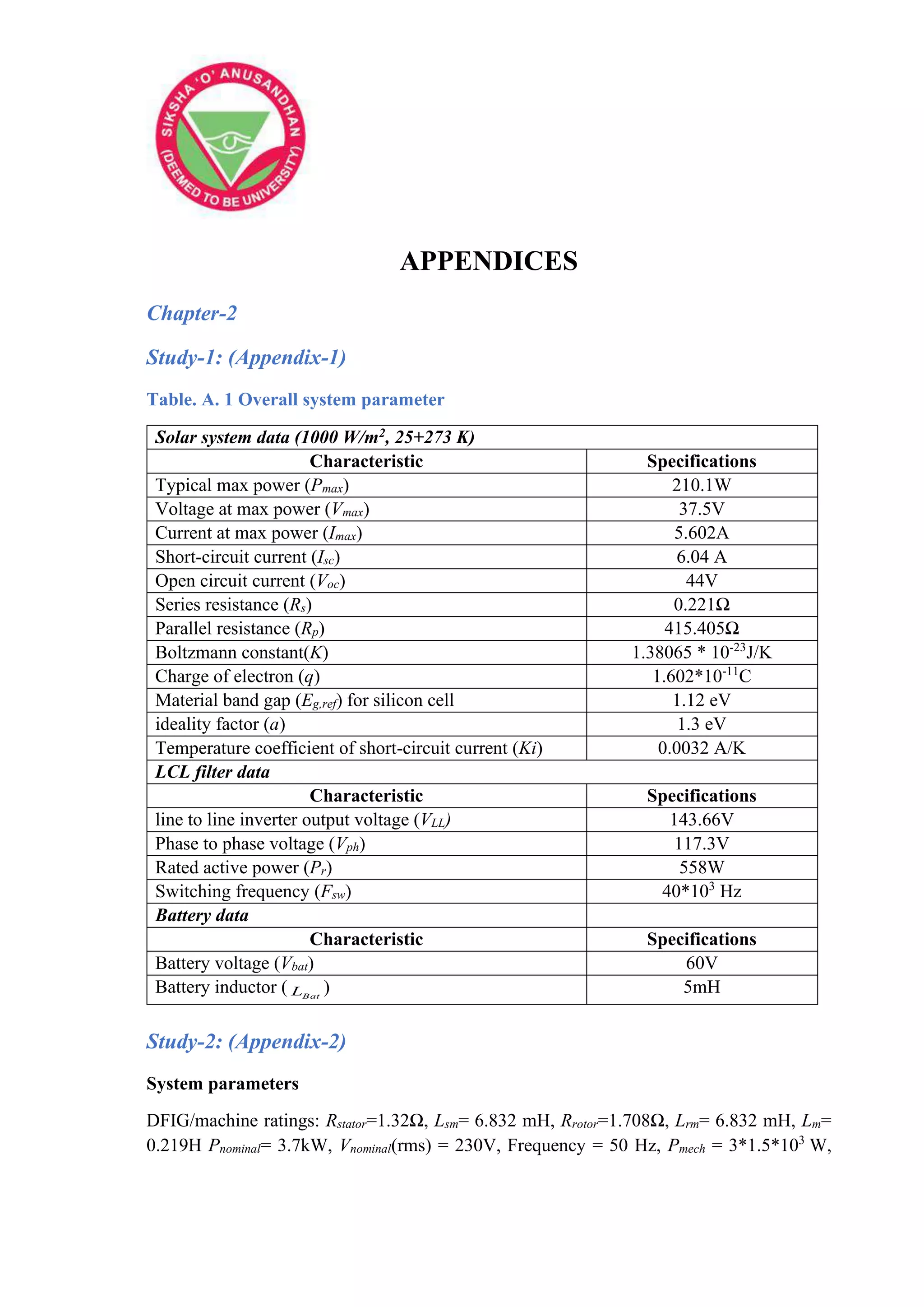
![374
APPENDICES
Pbase = 3*1.5*103
/0.9 VA, Wind speed= 12 m/s, rotational speed= 1.2 p.u, L= 4e-3H, C= 1e-
6F.
Study-3: (Appendix-3)
Table. A. 2 Design parameters
Simulation parameters Ratings
Source voltage: Vs, Rs, Ls 300V(L-L), 0.01Ω, 3e-3H
Non-linear load: PL, C 5.2kW, 10e-6F
SAPF: Vdc, Lf, Cf , C1,C2 300V,1e-3F,240e-6F,2200e-6F,2200e-6F
Idf,ref 4 to 6A
PF, QF 1.5kW, 7kVAR
PWM frequency, operating frequency 12.8kHZ, 50HZ
Chapter-3
Study-1: (Appendix-1) [352-353]
Table. A. 3 System Parameter
Solar Module constraints (1000 W/m2, 25ºC)
Characteristics Specifications Characteristics Specifications
PV maximum power (Pmax) 210W Nonlinear load voltage 50V
Maximum Voltage (Vmax) 37.5V Nonlinear load current 8A
Maximum Current (Imax) 5.602A Rated real Power (Pr) 1050W
Short circuit current (Isc) 6.04A Inverter Frequency
(Fsw)
40000 Hz
Open circuit Voltage (Voc) 44V Battery Voltage (Vb) 60V
Series Resistance (Rs) 0.221Ω Battery Inductor (Lb) 5mH
Equivalent Resistance (Rp) 415.405 Ω Grid L-L voltage
(Vgrid)
50V
Boltzmann constant (K) 1.38065*10-
23
J/K
C1 and C2 1000µF
Electron charge (q) 1.602*10-11
C La, Lb, Lc 500µH
Band gap of Silicon cell 1.12ev Ld, Le, Lf 900µH
Study-2: (Appendix-2)
System data: Rated power (Prated) = 5 MVA, Number of wind turbines (WT) = 3.
Double fed induction generator data: Rated power (PW) = 1.5 MW, Operating wind speed
( r
) = 15 m/s, Apparent power (Papp)= 1.66 MVA, Rated voltage (Vrated) = 0.575 kV, Pole
number (Np) = 6, Operating frequency = 50 Hz, Turns ratio from Stator to rotor = 575/1975,
Stator resistance (Rstator) = 0.0023 p.u., Stator inductance (Lstator)= 0.18 p.u., Rotor resistance
(Rrotor) = 0.0016 p.u., Rotor inductance (Lrotor)= 0.16 p.u., Inertia constant = 0.685](https://image.slidesharecdn.com/dr-211204045233/75/Robust-Active-Power-Filter-Controller-Design-for-Microgrid-and-Electric-Vehicle-Applications-part-2-174-2048.jpg)
![375
APPENDICES
Solid state transformer data: Low bus dc-link voltage (Vdc,low) = 1.15 kV, Working
frequency = 3 kHz, Turns ratio of the high frequency transformer = 1:50, high Frequency
transformer inductance = 5.95 μH, High dc-link voltage (Vdc,high) = 50 kV.
Study-3: (Appendix-3)
System parameters
Wind Turbine data: Rated Power (Prated) = 3.7kW, Rated Wind Velocity (Prated) = 12m/s.
Generator data: Rated apparent Power (Papp)= 1.615 kVA, Rated Frequency (Frated) = 50 Hz,
Stator and rotor turns ratio (Nr/Ns)= ½, Generator data contd.: Stator Resistance (Rs) =1.32Ω,
Stator Inductance (Lm,s) =6.832mH, Rotor Resistance (Rr)= 1.708 Ω, Rotor Inductance
(Lm,r)= 6.832mH, Mutual inductance (Lm) =0.219H, Stator rated rms current=12A, Rotor
rated rms current=18A.
Chapter-4
Study-1: (Appendix-1) [157-159]
Table. A. 4 Projected system data’s
System data’s Specifications
Utility voltage Vs = 230V (Phase-Phase voltage)
dc-grid voltage Vdc-grid = 500V
Stator impedance of the synchronous machine Rstator= 0.3Ω, Lstator= 2.5mH
Line impedance (distribution sector) Rs = 7.5m Ω, Ls= 25.7µH
LC-filter (Lf and Cf ) Lf = 1.3mH, Cf = 20 µF
Capacitance of the converter Cdc=300 µF
Loss resistance of converter and inverter R= 1m Ω
First Linear load PL,1 and QL,1 = 35 kW and 8 kVAr
Second Linear load PL,2 and QL,2 = 25 kW and 4 kVAr
Study-2: (Appendix-2)
SPR-305 PV: STC Power rating (Pm) =305W, No. of Cells=96, NOCT = C
45
, Voltage at
maximum power (VMPP) = 54.7V, Current at maximum power (IMPP) = 5.58A, Short-circuit
current (Isc) = 5.96 A, Open circuit current (Voc) = 64.2V, Kb=1.38*10-23
J/K, To=298K,
A=1.2, VSI: Vdc= 500V, Cdc= F
25000 , LF =0.4mH, Grid measurement: Vg= 260V, F =
60Hz, Load measurement:
3 current = 450A or 50A ,
1 current =50A
Study-3: (Appendix-3)
Utility parameters: Vg=220V, F=50Hz, Zg,abc=0.7Ω, 477µH, Sensitive Load: R-L based
rectifier=1.12kW, Dc-voltage: Vdc = 360V, Cdc = 3.4mF, SHAF and SEAF inductor: Lf =](https://image.slidesharecdn.com/dr-211204045233/75/Robust-Active-Power-Filter-Controller-Design-for-Microgrid-and-Electric-Vehicle-Applications-part-2-175-2048.jpg)
![376
APPENDICES
4.2mH, and Ls = 0.8mH, Solar Array: P=4.8kW, Voc= 415V, Isc = 14A, VMPP = 360.25V, IMPP
= 13.32A
Chapter-5
Study-1: (Appendix-1) [349-350]
System Parameter: Grid voltage:230V, dc-grid voltage: 500V, Stator impedance of PMSG:
Rstator= 0.3Ω, Lstator= 2.5mH, Line impedance of distribution system: Rline = 7.5m Ω, Lline=
25.7µH, LC -filter: Lfilter = 1.3mH, Cfilter= 20 µF, Capacitor of the ac-dc converter: C=300
µF, Loss resistance: R= 1m Ω, Nonlinear load: 60 kW and 12 kVAr
Table. A. 5 The switching states for different capacitor voltages
S.
No
Pole
Voltage
Switching States
(S1, S2, S3, S4, S5, S6, S7, S8) C1 C2 C3 C4
S.
No
Pole
Voltage
Switching States
(S1, S2, S3, S4, S5, S6, S7, S8) C1 C2 C3 C4
1 0 ✓ ✓ 0 0 0 0 42 8Vdc/16 ✓ + 0 0 0
2 Vdc/16 ✓ 0 0 0 - 43 9Vdc/16 ✓ ✓ - 0 0 -
3 ✓ ✓ 0 0 - + 44 ✓ ✓ ✓ - 0 - +
4 ✓ ✓ ✓ 0 - + + 45 ✓ ✓ ✓ ✓ - - + +
5 ✓ ✓ ✓ ✓ - + + + 46 ✓ ✓ + 0 0 -
6 ✓ ✓ ✓ ✓ + + + + 47 ✓ ✓ ✓ + 0 - +
7 2Vdc/16 ✓ 0 0 - 0 48 ✓ ✓ ✓ ✓ + - + +
8 ✓ ✓ 0 - + 0 49 ✓ ✓ ✓ ✓ ✓ 0 + + +
9 ✓ ✓ ✓ - + + 0 50 10Vdc/16 ✓ ✓ - 0 - 0
10 ✓ ✓ ✓ + + + 0 51 ✓ ✓ ✓ - - + 0
11 3Vdc/16 ✓ ✓ 0 0 - - 52 ✓ ✓ + 0 - 0
12 ✓ ✓ 0 - 0 + 53 ✓ ✓ ✓ + - + 0
13 ✓ ✓ ✓ 0 - + - 54 ✓ ✓ ✓ ✓ 0 + + 0
14 ✓ ✓ ✓ - + 0 + 55 11Vdc/16 ✓ ✓ ✓ - 0 - -
15 ✓ ✓ ✓ ✓ - + + - 56 ✓ ✓ ✓ - - 0 +
16 ✓ ✓ ✓ + + 0 + 57 ✓ ✓ ✓ ✓ - - + -
17 ✓ ✓ ✓ ✓ + + + - 58 ✓ ✓ ✓ + 0 - -
18 4Vdc/16 ✓ 0 - 0 0 59 ✓ ✓ ✓ + - 0 +
19 ✓ ✓ - + 0 0 60 ✓ ✓ ✓ ✓ + - + -
20 ✓ ✓ + + 0 0 61 ✓ ✓ ✓ ✓ 0 + 0 +
21 5Vdc/16 ✓ ✓ 0 - 0 - 62 ✓ ✓ ✓ ✓ ✓ 0 + + -
22 ✓ ✓ ✓ 0 - - + 63 12Vdc/16 ✓ ✓ - - 0 0
23 ✓ ✓ ✓ - 0 + + 64 ✓ ✓ + - 0 0
24 ✓ ✓ ✓ - + 0 - 65 ✓ ✓ ✓ 0 + 0 0
25 ✓ ✓ ✓ ✓ - + - + 66 13Vdc/16 ✓ ✓ ✓ - - 0 -
26 ✓ ✓ ✓ + 0 + + 67 ✓ ✓ ✓ ✓ - - - +
27 ✓ ✓ ✓ + + 0 - 68 ✓ ✓ ✓ + - 0 -
28 ✓ ✓ ✓ ✓ + + - + 69 ✓ ✓ ✓ ✓ + - - +
29 6Vdc/16 ✓ ✓ 0 - - 0 70 ✓ ✓ ✓ ✓ 0 0 + +
30 ✓ ✓ - 0 + 0 71 ✓ ✓ ✓ ✓ 0 + 0 -
31 ✓ ✓ ✓ - + - 0 72 ✓ ✓ ✓ ✓ ✓ 0 + - +
32 ✓ ✓ + 0 + 0 73 14Vdc/16 ✓ ✓ ✓ - - - 0
33 ✓ ✓ ✓ + + - 0 74 ✓ ✓ ✓ + - - 0
34 7Vdc/16 ✓ ✓ ✓ 0 - - - 75 ✓ ✓ ✓ 0 0 + 0
35 ✓ ✓ - 0 0 + 76 ✓ ✓ ✓ ✓ 0 + - 0
36 ✓ ✓ ✓ - 0 + - 77 15Vdc/16 ✓ ✓ ✓ ✓ - - - -
37 ✓ ✓ ✓ ✓ - + - - 78 ✓ ✓ ✓ ✓ + - - -
38 ✓ ✓ + 0 0 + 79 ✓ ✓ ✓ 0 0 0 +
39 ✓ ✓ ✓ + 0 + - 80 ✓ ✓ ✓ ✓ 0 0 + -
40 ✓ ✓ ✓ ✓ + + - - 81 ✓ ✓ ✓ ✓ ✓ 0 + - -
41 8Vdc/16 ✓ - 0 0 0 82 Vdc ✓ ✓ 0 0 0 0](https://image.slidesharecdn.com/dr-211204045233/75/Robust-Active-Power-Filter-Controller-Design-for-Microgrid-and-Electric-Vehicle-Applications-part-2-176-2048.jpg)