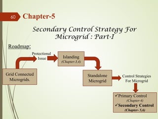
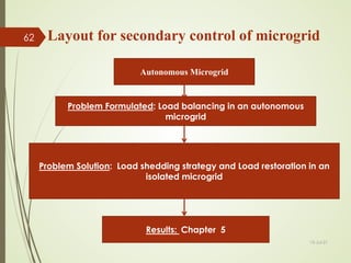
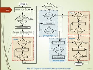
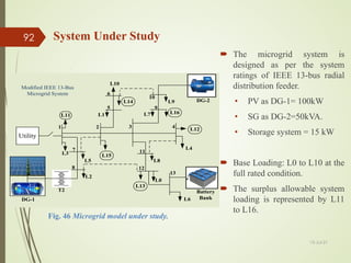
This document presents an overview of integrated protection and control strategies for microgrids. It discusses challenges in microgrid control and protection, including issues related to islanding detection. The author proposes a strategy to design a robust islanding detection method using feature selection algorithms. In Study 1, the author uses a modified multi-objective differential evolution algorithm coupled with an extreme learning machine classifier to select optimal feature subsets from offline simulation data of a modified IEEE 13-bus test system integrating different distributed generator types. The selected feature subsets are evaluated based on objectives like dependability, security, accuracy and number of features.


![Chapter 3: Study-1
Offline Feature Selection:
Design of a modified IEEE 13 bus system.
Generated about 1864 cases { Islanding=784, Non-Islanding=1080}.
About 45 features were studied [F1, .... F45]
Efficient features were selected by using Modified Multi-objective
differential evolution algorithm coupled with extreme learning machine
classifier.
5 Objective functions were considered: Dependability, Security, Accuracy,
F-measure, and the number of features.
Selected features also cross-validated their performance under noisy
environment.
13-Jul-21
18](https://image.slidesharecdn.com/integratedprotectionandcontrolstrategiesformicrogrid-210713153025/85/Integrated-protection-and-control-strategies-for-microgrid-18-320.jpg)
![Table 2 Obtained feature subsets through the proposed MMODE coupled ELM algorithm
Feature Without Noise
Dependability Security Accuracy F-Measure
[F10 F11] 100% 100% 100% 100%
[F11 F30] 100% 98.88% 99.35% 99.24%
[F10 F11 F39] 100% 100% 100% 100%
[F11 F30 F39] 100% 99.53% 99.73% 99.68%
[F11 F30 F39 F43] 100% 100% 100% 100%
[F11 F30 F31 F39 F43] 100% 99.62% 99.78% 99.74%
[F10 F11 F18 F31 F39 F43] 100% 100% 100% 100%
Feature At 30 dB Noise
Dependability Security Accuracy F-Measure
[F10 F11] 98.72% 98.61% 98.65% 98.41%
[F11 F30] 96.04% 98.59% 97.51% 97.03%
[F10 F11 F39] 99.87% 99.62% 99.73% 99.68%
[F11 F30 F39] 95.28% 98.33% 97.04% 96.44%
[F11 F30 F39 F43] 95.91% 98.14% 97.21% 96.65%
[F11 F30 F31 F39 F43] 97.44% 98.33% 97.96% 97.57%
[F10 F11 F18 F31 F39 F43] 98.72% 98.88% 98.81% 98.59%
Feature At 20 dB Noise
Dependability Security Accuracy F-Measure
[F10 F11] 92.72% 96.11% 94.68% 93.62%
[F11 F30] 90.68% 95.46% 93.45% 92.09%
[F10 F11 F39] 94.77% 97.12% 96.13% 95.37%
[F11 F30 F39] 91.45% 95.46% 93.77% 92.51%
[F11 F30 F39 F43] 92.21% 95.37% 94.04% 92.87%
[F11 F30 F31 F39 F43] 90.68% 93.70% 92.43% 90.97%
[F10 F11 F18 F31 F39 F43] 94.13% 94.13% 95.60% 94.73%
Table 3. Performance of the feature subsets under 30db and 20db noise, to select the optimum feature vector
19
Results of Study-1](https://image.slidesharecdn.com/integratedprotectionandcontrolstrategiesformicrogrid-210713153025/85/Integrated-protection-and-control-strategies-for-microgrid-19-320.jpg)
![(a) Islanding
Fig. 5 Case study for feature F-10 [Vneg/Vpos] , (±20%P and ±5% Q Variation).
(b) Non-Islanding
Fig. 6 Case study for feature F-11 [Vzero/Vpos]
13-Jul-21
20
Results of Study-1
(a) Islanding (b) Non-Islanding](https://image.slidesharecdn.com/integratedprotectionandcontrolstrategiesformicrogrid-210713153025/85/Integrated-protection-and-control-strategies-for-microgrid-20-320.jpg)
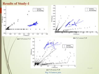
![Results of Study-1
(a) Islanding
Fig.7 Case study for feature F-39 [THD of Current]
Fig.8 Feature compared on the basis of Islanding and Non-Islanding Scenarios.
(b) F-11
(a) F-10 (c) F-39
13-Jul-21
21
(b) Non-Islanding](https://image.slidesharecdn.com/integratedprotectionandcontrolstrategiesformicrogrid-210713153025/85/Integrated-protection-and-control-strategies-for-microgrid-21-320.jpg)
![Ref Type of DG
used
Is feature
selection
applied?
Extracted
no. of
features
Features
considered
for islanding
detection
Detection
speed
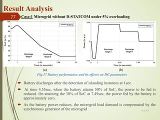
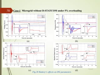
(msec)
Performance-based on the objective
function.
A D S FM
[28] MS No 11 11 - 91.6% 100% 83.3% 92.2%
[29] MI No 21 21 - 95.0% 100% 90.0% 95.7%
[30] MS Yes 11 3 - 100% 100% 100% 100%
[31] MS & MI Yes 21 4 180 100% - - -
[32] MS & MI Yes 27 11 30 97.5% 98.0% 97.1% -
Study-1 MS & MI Yes 45 3 75 100% 100% 100% 100%
*MS: Multiple Synchronous DG; MI: Multiple Inverter-based DG; A: Accuracy; D: Dependability; S: Security; FM: F-Measure.
Table.4 Comparative analysis of the proposed technique with the existing techniques
Comparative Analysis
13-Jul-21
23](https://image.slidesharecdn.com/integratedprotectionandcontrolstrategiesformicrogrid-210713153025/85/Integrated-protection-and-control-strategies-for-microgrid-23-320.jpg)
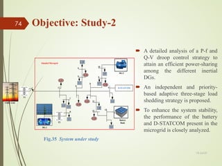
![ Study-1 is extended to design a strategy with zero NDZ, and reduced detection
time.
To comparatively reduce the optimization time and search space, the features
undertaken in the subsequent study is reduced to 16 highly sensitive features.
Findings: Study 1
Motivation to extend the study
The most efficient feature subset is concluded as [F-10 F-11 F-39].
Objective Function: minimizing the number of features and maximizing the
performance parameters in noisy environments.
The time taken to detect islanding based on ELM using selected feature vector is
approximately 75 milliseconds.
13-Jul-21
24](https://image.slidesharecdn.com/integratedprotectionandcontrolstrategiesformicrogrid-210713153025/85/Integrated-protection-and-control-strategies-for-microgrid-24-320.jpg)
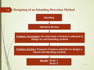
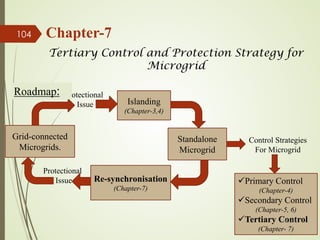
![Chapter 3: Study-2
Design of a Hybrid Islanding Detection Method (HIDM)
System Design: IEEE 13 bus system.
Generated Cases: 2064 cases.
Features Extracted : 16 sensitive features
Feature Selection: Modified Multi-objective differential evolution
algorithm coupled with an extreme learning machine classifier.
Objective Function: 1. Accuracy with Number of features.
2. Dependability with Number of features.
Accuracy based feature set used to design the passive method of
HIDM, [F1,F2,F4].
Dependability based feature set implemented in active method of
HIDM, [F9].
13-Jul-21
25](https://image.slidesharecdn.com/integratedprotectionandcontrolstrategiesformicrogrid-210713153025/85/Integrated-protection-and-control-strategies-for-microgrid-25-320.jpg)
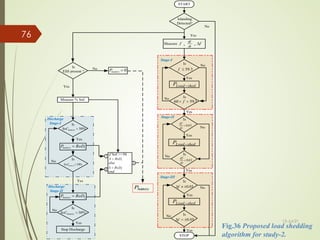
![Algorithm of the proposed HIDM
Start
16 sensitive feature extracted
for 2064 cases
Apply MMODEA-ELM using
objective function-1 and objection
function-2 independently.
Extraction of feature vector Fn
Where, n= number of features in vector
For objective function-1,n=1,2,3,4
For objective function-2,n=1,2,3,4
Cross-validate at noisy environment
Select an optimum feature vector for
both the objective function.
Measure voltage, current and
frequency from the PCC of an
operating system
Compute the features selected
from objective function-1
[F1 F2 F4]
Occurrence
of any variation in
the features?
No
Decision Tree
Yes
Island
detected?
Start injecting the disturbing
feature [F9] obtained from
objective function -2
No
-15<F1>+15
No
Detect
non-islanding
Islanding detected
Trip signal
Yes
Yes
Off-Line
Mode
On-Line
Mode
Observe the variations of F1
feature
Fig. 10 Flow-chart of the proposed offline and online approach
13-Jul-21
26](https://image.slidesharecdn.com/integratedprotectionandcontrolstrategiesformicrogrid-210713153025/85/Integrated-protection-and-control-strategies-for-microgrid-26-320.jpg)
![Features Dependability Features Accuracy
[F2] 100% [F 1 F2] 100%
[F8] 100% [F1 F2 F4] 100%
[F9] 100% [F6 F8 F15] 100%
[F15] 100% [F1 F2 F8 F15] 100%
Table 5 Performance of proposed algorithm for feature selection based on dependability and accuracy
Features Dependability Features Accuracy
At 30db noisy conditions
[F2] 96.07% [F 1 F2] 98.70%
[F8] 95.42% [F1 F2 F4] 98.88%
[F9] 100% [F6 F8 F15] 97.54%
[F15] 96.07% [F1 F2 F8 F15] 97.83%
At 20db noisy conditions
[F2] 92.81% [F 1 F2] 95.52
[F8] 90.84% [F1 F2 F4] 96.68%
[F9] 94.77% [F6 F8 F15] 94.37%
[F15] 91.50% [F1 F2 F8 F15] 94.66%
Table 6 Performance of ELM classifier on selected feature vectors
Off-line mode
13-Jul-21
27
Dependability: decreases the false identification rate; Accuracy: Accurate prediction of event](https://image.slidesharecdn.com/integratedprotectionandcontrolstrategiesformicrogrid-210713153025/85/Integrated-protection-and-control-strategies-for-microgrid-27-320.jpg)
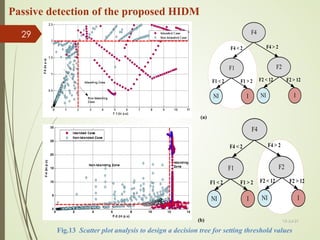
![F1
I
NI
F1 > 2
F1 < 2
I
NI
F2 > 12
F2 < 12
F2
F4
F4 > 2
F4 < 2
I: Islanding
NI: Non-Islanding
Fig.11 Decision Tree
[F4]: dQ/dt
[F1]: dv/dt
[F2]: df/dt
Pref
+
-
PDG
Power
PI Controller
Qref
+
-
QDG
Power
PI Controller
IDG
abc
dq
VPCC
abc
dq
PLL θ
Id
Iq
Vd
Vq
Current
PI Controller
Current
PI Controller
ωLf
ω
ωLf
Id_ref
Iq_ref
+
-
+
+
-
+
+
-
+
Vd_ref
Vq_ref
SPWM
m
φ
ω
Switch
Signal
Noise
Noise
+
+
+
Vd
Vq
Fig.12 Interface control
strategy for master DG
[F9]: df/dp
On-line mode
13-Jul-21
28](https://image.slidesharecdn.com/integratedprotectionandcontrolstrategiesformicrogrid-210713153025/85/Integrated-protection-and-control-strategies-for-microgrid-28-320.jpg)
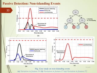
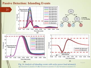
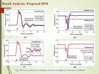
![ The injected value is set less than 3% of feature variations [F9].
The interruption is injected for a period of 5 cycles (i.e. from 0.58 seconds to 0.66
seconds).
The second threshold specified for feature F1 in active method is ±15 p.u.
Injection at 0.58 seconds in a small active power mismatch scenario, the islanding is
detected at 0.62 seconds as in Fig.15.(a).
A non-islanding case is verified with injection of disturbance in Fig.15.(b), which
remains detected as non-islanding.
(a) Islanding Event
Fig.15 Feature F1 response for active approach
(b) Non- Islanding Event
Active detection of the proposed HIDM](https://image.slidesharecdn.com/integratedprotectionandcontrolstrategiesformicrogrid-210713153025/85/Integrated-protection-and-control-strategies-for-microgrid-32-320.jpg)


![Hence the control signal can be framed as: )
( ref
Q
ref
bais Q
Q
m
f
f −
−
=
)
( ref
P
ref
bais P
P
m
V
V −
−
=
VPD: voltage real-power
drooping
FQB: frequency reactive-
power boosting
P
V
Q
f
Fig.21 VPD and FQB characteristics
47 Primary Control : Power Sharing
The VPD and FQB control strategy is implemented using the Self tuned Adaptive
Proportional Integral controller for efficient power sharing among the DGs.
( ) ( ) ( )
[ ]
t
Ke
p
p
p
p e
K
K
K
t
K −
−
−
= min
max
max
( ) ( ) ( )
[ ]
t
Ke
i
i e
K
t
K −
= max](https://image.slidesharecdn.com/integratedprotectionandcontrolstrategiesformicrogrid-210713153025/85/Integrated-protection-and-control-strategies-for-microgrid-47-320.jpg)


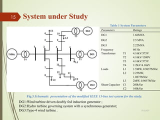
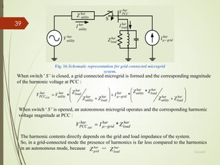
![Electrical Model of a Microgrid
The current vector of the microgrid network can be mathematically
represented by an admittance matrix and the voltage vector
13-Jul-21
94
( )
n
b
I
( )
n
n
b
Y × ( )
n
b
V
×
=
n
nn
n
n
n
n
n V
V
V
Y
Y
Y
Y
Y
Y
Y
Y
Y
I
I
I
.
.
.
.
.
.
.
.
.
.
.
.
.
.
.
.
.
.
.
.
2
1
2
1
2
22
21
1
12
11
2
1
The admittance matrix [Y] can be used to calculate the real and reactive
parameter of the branches.
( )
( )
=
+
≠
+
−
=
∑
≠
q
p
jB
G
q
p
jB
G
Y
q
p
pq
pq
pq
pq
pq
Since capacitated directed graph is of major focus, if the power flow from
node p to node q occurs, and the vice-versa power flow is
pq
pq Y
e = 0
=
pq
e](https://image.slidesharecdn.com/integratedprotectionandcontrolstrategiesformicrogrid-210713153025/85/Integrated-protection-and-control-strategies-for-microgrid-94-320.jpg)
![Centrality Index
The [Y] depicts the capacity of the distribution
feeders and defines the betweenness centrality
index.
• The betweenness centrality measures the
frequency of selecting a vertex while finding
the shortest path between the vertices.
Now, Let the maximum power flow between
vertex u and v be Fmax and the portion of power
flowing between p and q is fpq (i.e., p≠q).
The Centrality Index can be framed as:
The power flow can be normalised by:
Start
Deploy the microgrid according to the
principles represented in Section 2 and
create the adjacency matrix
Assign the graph interlinking with
proper capacity, according to the
admittance matrix
Estimate the utmost feasible power flow
from source to load ( )
max
F
The edges are ranked according to the
proportion of flow through them.
Stop
( )
Y
( )
E
Estimate the sum of power flow across each
edge for different source load pair( )
pq
C
Normalise the values by diving it from the
maximum flow in the system( )
nom
pq
C
Fig.47 Flowchart for identifying
and indexing the important edges
13-Jul-21
95
∑ ∑
=
x
u
y
v pq
pq f
CI
∑ ∑
∑ ∑
= x
u
y
v
x
u
y
v pq
pq
F
f
CI nom
max](https://image.slidesharecdn.com/integratedprotectionandcontrolstrategiesformicrogrid-210713153025/85/Integrated-protection-and-control-strategies-for-microgrid-95-320.jpg)


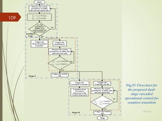
![Stage-I: Resynchronization controller
IEEE 1547 allows the
resynchronization process
after about 5 minutes from
the clearance of
disturbance.
Proposed algorithm
considers an addition
observation period of
0.4sec.
The controller starts
building up the microgrid
connected converter
parameters.
Stage-I is designed using a
moving average filter and
an adaptive proportional
integral controller .
dq
αβ
u
vα
MAF
u
vβ
MAF
u
q
v
u
d
v
dq
αβ
u
d
v
u
q
v
u
a
v
dq
αβ
u
vα
ˆ
u
vβ
ˆ
u
d V
v u
ˆ
ˆ =
u
q
v̂
u
u
d
q
v
v
ˆ
ˆ
u
lf
θ
µ
a
v −+
−+
API
API
+
+
+
+
DRFL
DRFL
s
ki
p
K
+
+ +
+
∫
u
lf
ω
u
θ
ˆ
u
θ
ˆ
u
b
v
u
c
v αβ
abc
µ
θˆ
u
V
ˆ
u
V
ˆ
µ
V
ˆ
u
θ
ˆ
µ
V
ˆ
µ
θˆ
c
V
ˆ
c
θˆ
µ
b
v
µ
c
v
Sin
+
)
ˆ
(
ˆ
c
u
c
t
w
Sin
V
θ
+
∗
t
u
ω
π
2
∗
∗ nom
f
T
6
π
−
+
Correction factor
SPWM
Converter
comp
V
ˆ
comp
θ
ˆ
[ ]
3
2
3
2
0 π
π
−
Fig. 54 Control strategy of the resynchronization controller
13-Jul-21
110](https://image.slidesharecdn.com/integratedprotectionandcontrolstrategiesformicrogrid-210713153025/85/Integrated-protection-and-control-strategies-for-microgrid-109-320.jpg)


![Work Published - Journal
[1] Chandak, S., & Rout, P. K. (2021). The implementation framework of a microgrid: A review. International
Journal of Energy Research, 45(3), 3523-3547.
[2] Chandak, S., & Rout, P. K. (2021). Seamless transition of microgrid between islanded and grid-connected
mode of operation. IET Energy System Integration.
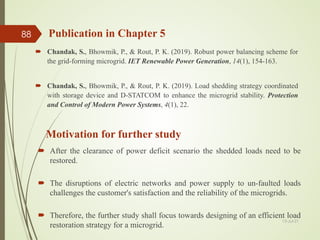
[3] Chandak, S., Bhowmik, P., & Rout, P. K. (2019). Robust power balancing scheme for the grid-forming
microgrid. IET Renewable Power Generation, 14(1), 154-163.
[4] Chandak, S., Bhowmik, P., & Rout, P. K. (2019). Dual-stage cascaded control to resynchronise an isolated
microgrid with the utility. IET Renewable Power Generation.
[5] Chandak, S., & Rout, P K. (2019). An Optimal Performance of a Self-healing Microgrid. IET Smart Grid.
[6] Chandak, S., Bhowmik, P., & Rout, P. K. (2019). Load shedding strategy coordinated with storage device and
D-STATCOM to enhance the microgrid stability. Protection and Control of Modern Power Systems, 4(1), 22.
[7] Chandak, S., Mishra, M., Nayak, S., & Rout, P. K. (2018). Optimal feature selection for islanding detection in
distributed generation. IET Smart Grid, 1(3), 85-95.
[8] Chandak, S., Mishra, M., & Rout, P. K. (2018). Hybrid islanding detection with optimum feature selection and
minimum NDZ. International Transactions on Electrical Energy Systems, 28(10), e2602.
[9] Chandak, S., Bhowmik, P., Mishra, M., & Rout, P. K. (2018). Autonomous microgrid operation subsequent to
an anti-islanding scheme. Sustainable cities and society, 39, 430-448.
[10] Mishra, M., Chandak, S., & Rout, P. K. (2019). Taxonomy of Islanding detection techniques for distributed
generation in microgrid. Renewable Energy Focus, 31, 9-30. 13-Jul-21](https://image.slidesharecdn.com/integratedprotectionandcontrolstrategiesformicrogrid-210713153025/85/Integrated-protection-and-control-strategies-for-microgrid-125-320.jpg)
![[11] Chandak, S., Mishra, M., & Rout, P. K. (2018, October). A Novel Active Anti-
islanding Scheme for Inverter-Based Distributed Generation. In 2018 2nd IEEE
International Conference on Power Electronics, Intelligent Control and Energy Systems
(ICPEICES) (pp. 431-436). IEEE.
[12] Pattnaik, R., Chandak, S., Rout, P. K., Routray, S. K., & Sahu, B. K. (2020, July).
Design and analysis of automatic generation control of two area power system
based on modified differential evolution algorithm. In 2020 International
Conference on Computational Intelligence for Smart Power System and Sustainable
Energy (CISPSSE) (pp. 1-6). IEEE.
Work Published - Conference
13-Jul-21
129
[13] Chandak, S., & Rout, P. (2020). Microgrids During the Outbreak of COVID-19.
IEEE Smart Grid eNewsletter, (pp.9-11), July 2020.
Work Published - Newsletter](https://image.slidesharecdn.com/integratedprotectionandcontrolstrategiesformicrogrid-210713153025/85/Integrated-protection-and-control-strategies-for-microgrid-126-320.jpg)

![References
[1] IEEE Application Guide for IEEE Std 1547™: 'IEEE Standard for Interconnecting Distributed
Resources with Electric Power Systems', 2009.
[2] Std, U. L.1741. Inverters, Converters, and Controllers for Use in Independent Power
Systems,2002.
[3] Kersting, W.H., 1991. Radial distribution test feeders. IEEE Transactions on Power Systems, 6(3),
pp.975-985.
[4] Giroux, P., Sybille, G., Osorio, C. and Chandrachood, S., 2012. 100-kW grid-connected PV array
demo detailed model. MathWorks File Exchange.
[5] Cagnano, A., De Tuglie, E. and Mancarella, P., 2020. Microgrids: Overview and guidelines for
practical implementations and operation. Applied Energy, 258, p.114039.
[6] Hooshyar, A. and Iravani, R., 2017. Microgrid protection. Proceedings of the IEEE, 105(7),
pp.1332-1353.
[7] Zamora, R. and Srivastava, A.K., 2010. Controls for microgrids with storage: Review, challenges,
and research needs. Renewable and Sustainable Energy Reviews, 14(7), pp.2009-2018.
[8] Shayeghi, H., Shahryari, E., Moradzadeh, M. and Siano, P., 2019. A survey on microgrid energy
management considering flexible energy sources. Energies, 12(11), p.2156.
[9] Storn, R. and Price, K., 1997. Differential evolution–a simple and efficient heuristic for global
optimization over continuous spaces. Journal of global optimization, 11(4), pp.341-359.
13-Jul-21
131](https://image.slidesharecdn.com/integratedprotectionandcontrolstrategiesformicrogrid-210713153025/85/Integrated-protection-and-control-strategies-for-microgrid-128-320.jpg)
![[10] Zaky, M.S., 2015. A self-tuning PI controller for the speed control of electrical motor drives. Electric
Power Systems Research, 119, pp.293-303.
[11] Merino, J., Mendoza-Araya, P., Venkataramanan, G. and Baysal, M., 2014. Islanding detection in
microgrids using harmonic signatures. IEEE Transactions on Power Delivery, 30(5), pp.2102-2109.
[12] Reddy, C.P., Chakrabarti, S. and Srivastava, S.C., 2013. A sensitivity-based method for under-frequency
load-shedding. IEEE Transactions on Power Systems, 29(2), pp.984-985.
[13] Wang, Y., Zhou, R. and Wen, C., 1993, January. Robust load-frequency controller design for power
systems. In IEE proceedings C (generation, transmission and distribution) (Vol. 140, No. 1, pp. 11-16).
IET Digital Library.
[14] Majumder, R., Ghosh, A., Ledwich, G. and Zare, F., 2009, December. Power sharing and stability
enhancement of an autonomous microgrid with inertial and non-inertial DGs with DSTATCOM. In 2009
International Conference on Power Systems (pp. 1-6). IEEE.
[15] Abu-Elanien, A.E., Salama, M.M.A. and Shaban, K.B., 2018. Modern network reconfiguration
techniques for service restoration in distribution systems: A step to a smarter grid. Alexandria engineering
journal, 57(4), pp.3959-3967.
[16] Manjunath, K. and Mohan, M.R., 2007. A new hybrid multi-objective quick service restoration technique for electric
power distribution systems. International Journal of Electrical Power & Energy Systems, 29(1), pp.51-64.
[17] Ford, L.R. and Fulkerson, D.R., 1956. Maximal flow through a network. Canadian journal of
Mathematics, 8, pp.399-404.
[18] Srinivas, V.L., Singh, B. and Mishra, S., 2019. A Self-Synchronizing VSM with Seamless Operation
during Unintentional Islanding Events. IEEE Transactions on Industrial Informatics. 13-Jul-21
132
References](https://image.slidesharecdn.com/integratedprotectionandcontrolstrategiesformicrogrid-210713153025/85/Integrated-protection-and-control-strategies-for-microgrid-129-320.jpg)


![Work Published - Journal
[1] Chandak, S., & Rout, P. K. (2021). The implementation framework of a microgrid: A review. International
Journal of Energy Research, 45(3), 3523-3547.
[2] Chandak, S., & Rout, P. K. (2021). Seamless transition of microgrid between islanded and grid-connected
mode of operation. IET Energy System Integration.
[3] Chandak, S., Bhowmik, P., & Rout, P. K. (2019). Robust power balancing scheme for the grid-forming
microgrid. IET Renewable Power Generation, 14(1), 154-163.
[4] Chandak, S., Bhowmik, P., & Rout, P. K. (2019). Dual-stage cascaded control to resynchronise an isolated
microgrid with the utility. IET Renewable Power Generation.
[5] Chandak, S., & Rout, P K. (2019). An Optimal Performance of a Self-healing Microgrid. IET Smart Grid.
[6] Chandak, S., Bhowmik, P., & Rout, P. K. (2019). Load shedding strategy coordinated with storage device and
D-STATCOM to enhance the microgrid stability. Protection and Control of Modern Power Systems, 4(1), 22.
[7] Chandak, S., Mishra, M., Nayak, S., & Rout, P. K. (2018). Optimal feature selection for islanding detection in
distributed generation. IET Smart Grid, 1(3), 85-95.
[8] Chandak, S., Mishra, M., & Rout, P. K. (2018). Hybrid islanding detection with optimum feature selection and
minimum NDZ. International Transactions on Electrical Energy Systems, 28(10), e2602.
[9] Chandak, S., Bhowmik, P., Mishra, M., & Rout, P. K. (2018). Autonomous microgrid operation subsequent to
an anti-islanding scheme. Sustainable cities and society, 39, 430-448.
[10] Mishra, M., Chandak, S., & Rout, P. K. (2019). Taxonomy of Islanding detection techniques for distributed
generation in microgrid. Renewable Energy Focus, 31, 9-30. 13-Jul-21](https://image.slidesharecdn.com/integratedprotectionandcontrolstrategiesformicrogrid-210713153025/85/Integrated-protection-and-control-strategies-for-microgrid-132-320.jpg)