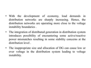
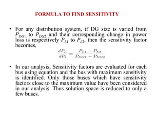
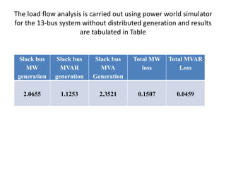
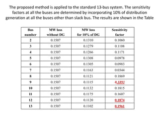
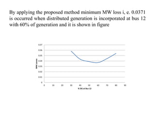
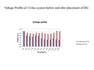
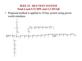
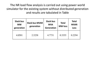
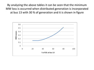
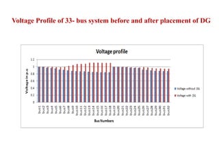
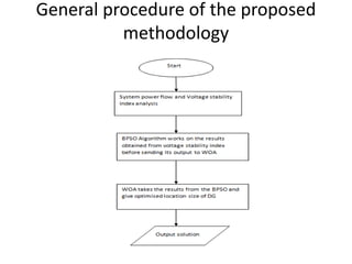
This document discusses distributed generation (DG) integration in distribution systems. It provides background on DG, including definitions and how DG can be operated in grid-connected or autonomous modes. The document reviews literature on DG planning and optimization techniques. It then states the problems of increased DG penetration, including potential voltage stability issues. The objectives of the proposed research are to enhance voltage stability with DG integration by optimizing DG location and size using sensitivity factors and a hybrid optimization algorithm. Formulas for calculating sensitivity factors are also presented. The document concludes by discussing simulation results and analysis.
![LITERATURE SURVEY
• Distributed Generation (DG) is small-scale generation units located near or at
loads. However, the definition can be diversified based on voltage level, unit
connection, type of prime-mover and maximum power rating [1].
• IEEE [2] defines DG as “the generation of electricity by facilities that are
sufficiently smaller than central generating plants so as to allow
interconnection at nearly any point in a power system.
• A good number of research work is going on DG integration with grid and its
safe and reliable operation [3][4].
• In the literature, DG planning has been proposed based on power loss
minimisation,voltage stability improvements, reliability improvements etc.
These planning techniques are followed by different methods, i.e., different
analytical, heuristic approaches, and meta-heuristics based on evolutionary
algorithms.](https://image.slidesharecdn.com/voltagestabilityanalysiswithdgnew1-230419072551-6ab623f6/85/Voltage_Stability_Analysis_With-DG-NEW-1-pptx-3-320.jpg)
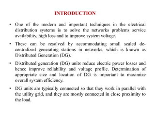
![• In the paper [5][6] authors have used the analytical method and rule of thumb
for analysing the distribution system which is radial and has uniformly
distributed loads. Rule is simple and easy to use, according to which the DG
size is 2/3 that of the kVar load and it is located at 2/3 of the distance from a
radial feeder but it cannot provide the proper solution when the load
distribution type is changed. Moreover, it can not be applied in meshed
network.
• In the paper [7], an analytical approach has been presented to identify
appropriate location to place single DG in radial as well as loop systems to
minimize losses. But, in this approach, optimal sizing is not considered.
• For dealing with DG sizing and placement issues, heuristic methods have
been proposed by several researchers [8][9]. To ensure the optimal use of an
existing network’s assets, a methodology based on linear programming (LP)
is proposed.](https://image.slidesharecdn.com/voltagestabilityanalysiswithdgnew1-230419072551-6ab623f6/85/Voltage_Stability_Analysis_With-DG-NEW-1-pptx-4-320.jpg)
![• For selection of optimum size and location of DG, several genetic
algorithms (GA) and fuzzy logic based methods have been discussed in
[10][11][12]], Although GA provides almost near optimum output but they
are computationally very demanding and have a slow convergence .
• As load flow represents the system states, therefore it can be used for
planning the future expansion of power systems. We can calculate the
system loss from the load flow result and doing the load flow repeatedly,
we can easily tell the location and size of DG for which we get the
minimum power loss of the system. This method is known as exhaustive
load flow (ELF) method. Although this ELF method gives the exact
answer; however, it needs lots of load flow computation. Therefore, ELF
method needs to be optimized to get accurate answer and less
computational time.
• Although the integration of the DG units in electric systems has
multifarious benefits, they increase the complexity [13]. Therefore, the DG
units have impacts on the system performance such as voltage profile,
power flow, system losses, power quality, stability, reliability, and
protection [14]. The main target of this research is to study the voltage
stability due to the high penetration of the DG units[15][16].](https://image.slidesharecdn.com/voltagestabilityanalysiswithdgnew1-230419072551-6ab623f6/85/Voltage_Stability_Analysis_With-DG-NEW-1-pptx-5-320.jpg)
![• The stability of a power system is defined as “a property of a power
system that enables it to remain in a state of equilibrium under
normal operating conditions and to regain an acceptable state of
equilibrium after being subjected to a disturbance” [17].
• Therefore, the penetration of DG units into distribution systems
affects the stability of the system, and as the penetration level
increases, stability becomes a significant issue [18]. Any fault
occurring in the distribution system might cause voltage and angle
instability.
• Because of increase in load demand the distribution system is facing
problems. They are experiencing many changes from a low level to
high level of load. M. Chakravorty, D. Das [19] proposed a voltage
stability index technique for radial distribution systems. Voltage
Stability Index (VSI) represents a numerical solution to identify the
sensitive node of the system.](https://image.slidesharecdn.com/voltagestabilityanalysiswithdgnew1-230419072551-6ab623f6/85/Voltage_Stability_Analysis_With-DG-NEW-1-pptx-6-320.jpg)
![• Optimal placement of multi-distributed generation units including
different load models using particle swarm optimization for loss
minimization and voltage profile improvement is explained in [20].
• The comparison of Harmony Search Algorithm and Particle Swarm
Optimization for Distributed Generation Allocation to Improve
Steady State Voltage Stability of Distribution Networks with
different methods is done in [21].
• The Power flow study and voltage stability analysis for radial
system with distributed generation by using different index is
explained in [22][23].](https://image.slidesharecdn.com/voltagestabilityanalysiswithdgnew1-230419072551-6ab623f6/85/Voltage_Stability_Analysis_With-DG-NEW-1-pptx-7-320.jpg)


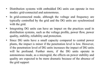
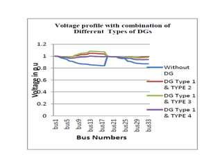
![Types of Distributed Generation (DG).
The DG’s are grouped into four major types based on the real and
reactive power delivering capability [6].
• Type1: DG capable of delivering both active and reactive power.
DG units based on synchronous machines (cogeneration, gas
turbine, etc.) come under this type.
• Type2: This type of DG is capable of delivering only active power
such as photovoltaic, micro turbines, fuel cells, which are
integrated to the main grid with the help of converters/inverters.
• Type3: DG capable of delivering only reactive power. Synchronous
compensators such as gas turbines and capacitor banks are the
example of this type and operate at zero power factors.
• Type4: DG capable of delivering active power but consuming
reactive power. Mainly induction generators, which are used in
wind farms, come under this category. However, doubly fed
induction generator (DFIG) systems may consume or produce
reactive power i.e. operates similar to synchronous generator](https://image.slidesharecdn.com/voltagestabilityanalysiswithdgnew1-230419072551-6ab623f6/85/Voltage_Stability_Analysis_With-DG-NEW-1-pptx-41-320.jpg)
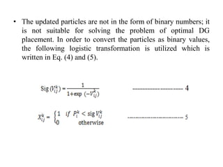
![• The BPSO creates the set of initial particles bit strings and constrains
the velocity value in the interval of [0 1]. Hence, the BPSO algorithm is
utilized to improve the reliability of the distribution network by
minimizing the power losses.
• In N-dimensional search space, Xi = [xi1, xi2, … xiN] and Vi = [vi1, vi2, …
viN] are the two vectors associated with each particle i. During their
search, particles trade information with each others in a definite way
to optimize their search experience. There are different variants of
the particle swarm paradigms but the most commonly used one is the
Gbest model where the whole population is considered as
a single neighborhood throughout the optimization process [16].
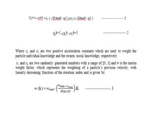
• During each iteration, the particle with the best solution shares its
position coordinates (Gbest) information with the remainder of the
swarm. Then, each particle updates its coordinates based on its own
best search experience (Pbest) and Gbest according to the following
equations [1]](https://image.slidesharecdn.com/voltagestabilityanalysiswithdgnew1-230419072551-6ab623f6/85/Voltage_Stability_Analysis_With-DG-NEW-1-pptx-57-320.jpg)
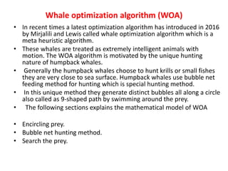
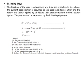
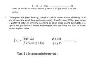
![Bubble-net hunting method
a.Shrinking encircling mechanism
• This technique is applied by linearly decreasing the value of from 2 to 0 which
is any value between [-a, a]. The Randomly selected value for a vector is in the
range of [-1, 1]. The updated position of A is obtained between initial position
and current best agent position.
b.Spiral updating position
• To represent the helix-shaped movement between humpback whale and prey
the mathematical equation is written and is given by:](https://image.slidesharecdn.com/voltagestabilityanalysiswithdgnew1-230419072551-6ab623f6/85/Voltage_Stability_Analysis_With-DG-NEW-1-pptx-62-320.jpg)

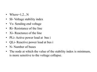
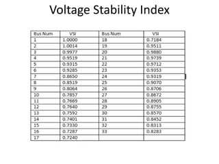
![Voltage Stability Index
• Voltage stability analysis could be performed in a power
system by evaluating the derived voltage stability index.
• The values of the voltage stability index would indicate the
distance to voltage collapse for a given loading condition.
• These indices are taken as an reference that will measure the
stability condition and optimal position of DG will be selected
initially in the power system.
• The voltage stability index (SI) used in this work is developed
for distribution line model from the quadratic equation and is
given by[10]](https://image.slidesharecdn.com/voltagestabilityanalysiswithdgnew1-230419072551-6ab623f6/85/Voltage_Stability_Analysis_With-DG-NEW-1-pptx-66-320.jpg)
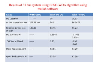
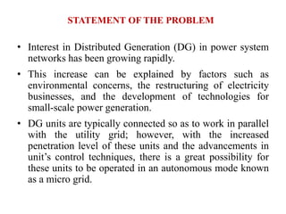
![Comparison results of IEEE-33 Bus system with other
methods
Method DG Size MW DG Location Power loss
KW
% Reduction in
power Loss
PSO[14] 2.576 6 103.98 48.69
WOA[16] 1.255 15 108.406 46.51
Proposed
(BPSO-WOA)
1.6545 18 94.01 53.61](https://image.slidesharecdn.com/voltagestabilityanalysiswithdgnew1-230419072551-6ab623f6/85/Voltage_Stability_Analysis_With-DG-NEW-1-pptx-73-320.jpg)


![[10] Presented a paper on “Integration of Solar Photovoltaic Generation in a
Practical Distribution System for Loss Minimization and Voltage Stability
Improvement” in the virtual conference organized by the Department of Electrical
& Electronics Engineering, NMAM Institute of Technology, Nitte during 22 and 23
December 2020.
[11] Rudresha S. J. and Dr. Shekhappa G. Ankaliki, Dr. T. Ananthapadmanabha,Girish
v”Application of hybrid techniques for optimal position and sizing of distributed
generation units in radial distribution system” International Journal of Electrical
Engineering & Technology (IJEET), Volume 12, Issue 2, February 2021, pp. 90-99;
ISSN Print: 0976-6545 and ISSN Online: 0976-6553](https://image.slidesharecdn.com/voltagestabilityanalysiswithdgnew1-230419072551-6ab623f6/85/Voltage_Stability_Analysis_With-DG-NEW-1-pptx-80-320.jpg)
![[13] Lopes, J. A. P (2002), “Integration of Dispersed Generation on
Distribution Networks – Impact Studies”, PES Winter Meeting, IEEE, Vol.
1, pp.323-328
[14]. Rohit Fanish, Jitendra Singh Bhadoriya “Optimal Placement of Multi DG
in 33 Bus System Using PSO “International Journal of Advanced Research
in Electrical, Electronics and Instrumentation Engineering, Vol. 4, Issue 4,
April 2015,pp- 2278 – 8875.
[15] C. Borges and D. Falcao, “Impact of Distributed Generation Allocation
and Sizing on Reliability, Losses and Voltage Profile,” in Power Tech
Conference Proceedings, 2003 IEEE Bologna, Vol. 2, June 2003, p. 5.
[16] P. Dinakara Prasad Reddy, V. C. Veera Reddy and T. Gowri
Manohar “Whale optimization algorithm for optimal sizing of
renewable resources for loss reduction in distribution systems”
Renewables (2017) 4:3 DOI 10.1186/s40807-017-0040-1.](https://image.slidesharecdn.com/voltagestabilityanalysiswithdgnew1-230419072551-6ab623f6/85/Voltage_Stability_Analysis_With-DG-NEW-1-pptx-81-320.jpg)
![[17] Masoud Esmaili, “Placement of Minimum Distributed Generation Units
Observing Power Losses and Voltage Stability with Network Constraints”,
IET Gen. Trans. Distrib., Vol.7, Issue.8, pp.813-821, 2013.
[18] Milanovic, J.V.; David, T. M (2002), “Stability of Distribution Networks
with Embedded Generators and Induction Motors”, PES Winter Meeting,
IEEE, Vol. 2, pp. 1023 -1028
[19] M. Chakravorty, D. Das, “Voltage Stability Analysis of Radial
Distribution Networks”, International Journal Of Electrical Power and
Energy Systems, Vol.23, (2), pp.129 – 135, 2001.
[20] El-Zonkoly, A.M. “Optimal Placement of Multi-Distributed Generation
Units Including Different Load Models Using Particle Swarm
Optimization”, IET Gener. Transm. Distrib., 5, (7), pp. 760–771, 2011.
[21] H. Piarehzadeh, A. Khanjanzadeh and R. Pejmanfer. “Comparison of
Harmony Search Algorithm and Particle Swarm Optimization for
Distributed Generation Allocation to Improve Steady State Voltage
Stability of Distribution Networks”, Research Journal of Applied Sciences,
Engineering and Technology, Vo.l/Issue: 4(15), pp. 2310-2315, 2012.](https://image.slidesharecdn.com/voltagestabilityanalysiswithdgnew1-230419072551-6ab623f6/85/Voltage_Stability_Analysis_With-DG-NEW-1-pptx-82-320.jpg)
![[22] Adnan anwar and H. R. Pota, (2011) Member, IEEE “Loss Reduction of
Power Distribution Network Using Optimum Size and Location of
Distributed Generation”.
[23] Mostafa H. Mostafa “Power Flow Study and Voltage Stability Analysis
for Radial System with Distributed Generation” IJCP, Vol.137, No.9,
March 2016.
[24]Yuvaraj Thangaraja,Ravi Kuppan ”Multi-objective Simultaneous
Placement of DG and DSTATCOM Using Novel Lightning Search
Algorithm”, Journal of Applied Research and Technology (2017) 477–491.
[25] Sirine Essallah, Adel Bouallegue and Adel Khedher “ Optimal Sizing and
Placement of DG Units in Radial Distribution System “ International
journal of renewable energy research , Vol.8, No.1, March, 2018 .
[26] Reza Baghipour, Seyyed Mehdi Hosseini “Placement of DG and
Capacitor for Loss Reduction, Reliability and Voltage Improvement in
Distribution Networks Using BPSO” I.J. Intelligent Systems and
Applications, 2012, 12, 57-64.](https://image.slidesharecdn.com/voltagestabilityanalysiswithdgnew1-230419072551-6ab623f6/85/Voltage_Stability_Analysis_With-DG-NEW-1-pptx-83-320.jpg)


![[IJET-V1I4P9] Author :Su Hlaing Win](https://cdn.slidesharecdn.com/ss_thumbnails/ijet-v1i4p9-150824171458-lva1-app6891-thumbnail.jpg?width=640&height=640&fit=bounds)