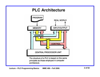
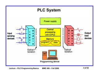
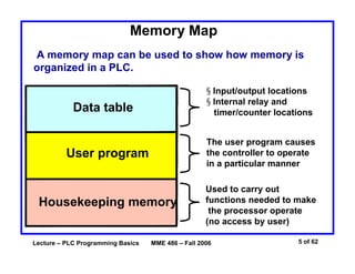
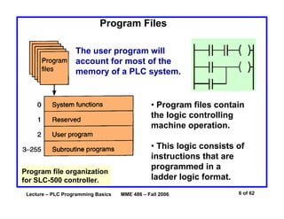
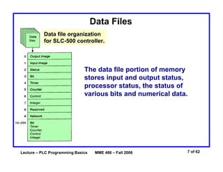
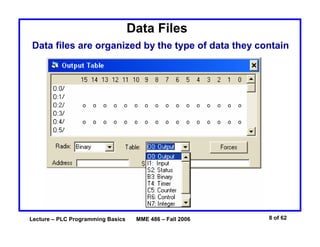
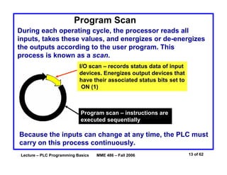
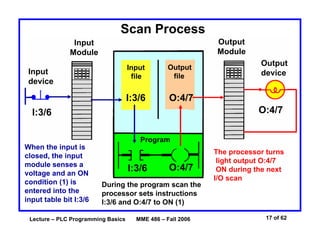
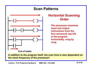
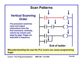
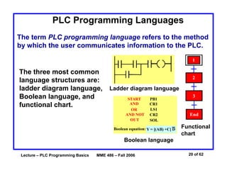
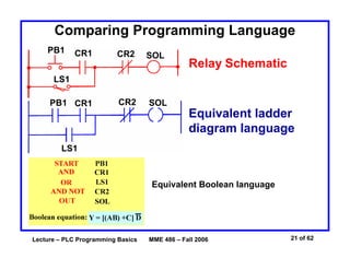
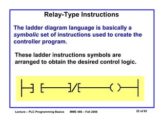
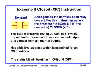
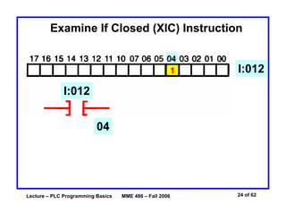
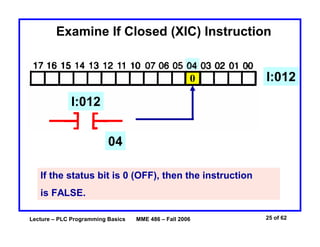
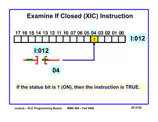
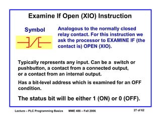
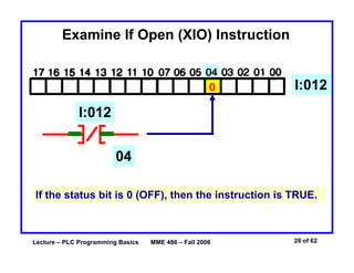
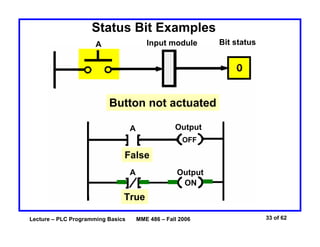
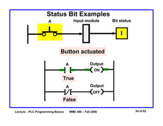
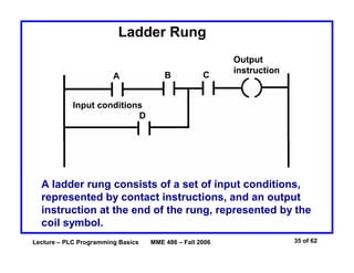
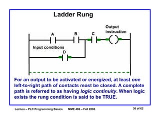
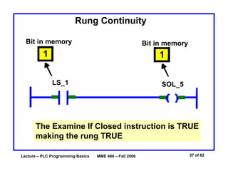
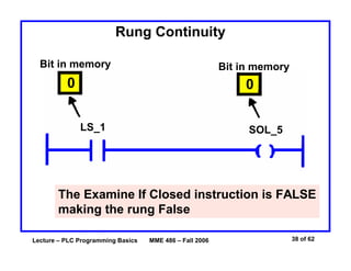
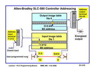
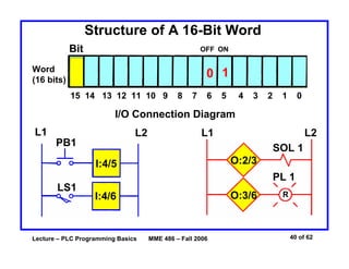
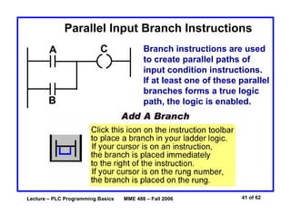
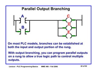
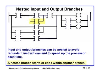
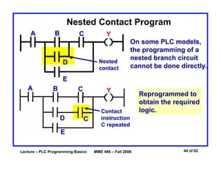
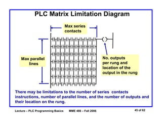
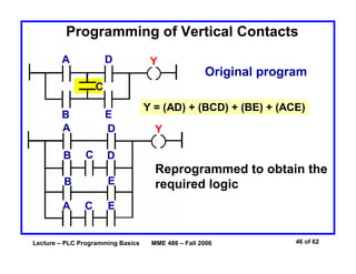
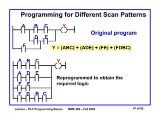
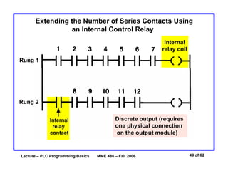
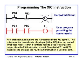
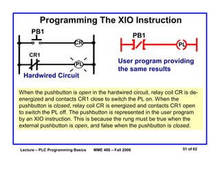
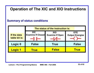
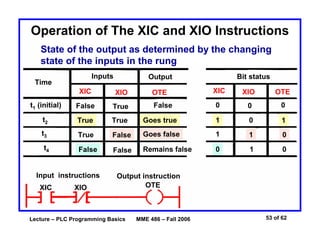
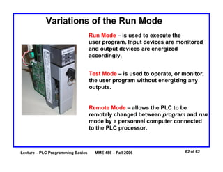
The document discusses the basics of programmable logic controller (PLC) programming including PLC architecture, memory organization, programming languages, ladder logic instructions, addressing schemes, and programming techniques. Specifically, it covers the processor memory being divided into program and data memory, the ladder logic programming language using relay-type instructions like examine if closed and examine if open, addressing I/O locations by module and bit, and programming concepts such as parallel and nested rungs, internal control relays, and adjustments for different scan patterns.
PLC ARCHITECTURE AND HARDWARE COMPONENTSAkshay Dhole
Explains about the basics of PLC ARCHITECTURE AND HARDWARE COMPONENTS.
A Programmable Logic Controller (PLC) is a specialized computing system used for control of industrial machines and processes.
A PLC is a computer designed to work in an industrial environment
PLC Ladder Diagram basics, with two solved examples
For more information go to
http://shrutizpresentations.blogspot.in/2014/04/plc-ladder-diagram-basics.html
Seminar Presentation on Programmeble Logic Controller , By an Engineering Student For doing Professional Presentation like Business Presentation, Industrial automation process,
In this session you will learn:
Programmable Logic Controller(PLC)
Types of PLC’s
PLC architecture
Scan cycles
Scan patterns
PLC programming
Ladder diagram programming
Latch and Unlatch
DCS architecture
For more information, visit: https://www.mindsmapped.com/courses/industrial-automation/complete-training-on-industrial-automation-for-beginners/
Seminar Presentation on Programmeble Logic Controller , By an Engineering Student For doing Professional Presentation like Business Presentation, Industrial Use
Unlock full featured course with 250+ Video Lectures at 20% Discount for "Learn 5 PLC's in a Day" lifetime E-Learning course for 39 USD only: https://www.udemy.com/nfi-plc-online-leaning/?couponCode=slideshare2016
Enroll for Advanced Industrial Automation Training with PLC, HMI and Drive Combo with 300+ Video Lecture for 69.3 USD only: http://online.nfiautomation.org/catalog/1769?couponCode=LEARNING_MADE_EASY
PowerPoint Presentation on Industrial Automation In which we discuss About PLCs, SCADA,HMI,VFD and various tools of Automation which is used in Industries.
Like Comment & Share
Do you want to know more about PLC and control systems then this lecture will be beneficial to you. This lecture/PPT contains all the basic views about PLC and Control Systems.
If you are more very curious to Know more about PLC, SCADA, DCS, HMI, VFD, Panel Designing, AutoCAD etc... then feel free to contact to me. My Contact no. Is. 9718474287.
Operations & Maintenance:
• Plant maintenance, ensuring that all plant equipment are functioning at optimum
performance levels.
• Executing trouble shooting and predictive, routine, breakdown & shutdown
maintenance of all types of machineries. Minimizing bottlenecks for achieving
high productivity with maximization of men, material & machine.
• Identifying areas of improvement and recommending equipment calibrations to
enhance operational efficiencies of machine / equipment.
Erection & Commissioning:
• As a team leader - supervision of erection & commissioning of machineries and
equipments.
• Testing & functioning of equipment and removing technical errors in the
functioning.
For free download Subscribe to https://www.youtube.com/channel/UCTfiZ8qwZ_8_vTjxeCB037w and Follow https://www.instagram.com/fitrit_2405/ then please contact +91-9045839849 over WhatsApp.
Programmable Logic Controller (PLC) is a specialized computing system used for control of industrial machines and processes.
An introduction to PLC languages - Instruction Language (IL) , Functional Block Diagram (FBD) , Ladder Logic Diagram (LD) and Sequential Function Chart (SFC).
(Download and open with Adobe Reader to see animations)
For free download Subscribe to https://www.youtube.com/channel/UCTfiZ8qwZ_8_vTjxeCB037w and Follow https://www.instagram.com/fitrit_2405/ then please contact +91-9045839849 over WhatsApp.
Internship report on working of CNC and PLC in BHEL, Jhansi
Difference between micro controller and PLC, Introduction to PLC.,
PLC structure at glance,
PLC structure,
I/O processing,
Ladder Diagram Fundamentals,
PLC for industrial Prose cc control,
Selection criteria for PLC
A PLC is a digital operating electronic apparatus.
Which uses a programmable memory for internal storage of instruction for implementing specific function such as logic, sequencing, timing, counting and arithmetic to control through analog or digital input/output modules various types of machines or process.
Building Cultural Awareness through EmotionPresented By Team .docxhartrobert670
Building Cultural Awareness through Emotion
Presented By: Team A
Psy450 - Diversity and
Cultural Factors
in Psychology
9/21/15
Stefanie Krasner
Introduction
Make Effective Presentations
Using Awesome Backgrounds
Engage your Audience
Capture Audience Attention
Understanding Chinese Culture
Make Effective Presentations
Using Awesome Backgrounds
Engage your Audience
Capture Audience Attention
The Human Being and Emotion
Product A
Feature 1
Feature 2
Feature 3
Product B
Feature 1
Feature 2
Feature 3
The Human Being and Emotion
Make Effective Presentations
Using Awesome Backgrounds
Engage your Audience
Capture Audience Attention
Universality of Emotion
Product A
Feature 1
Feature 2
Feature 3
Product B
Feature 1
Feature 2
Feature 3
Universality of Emotion
Make Effective Presentations
Using Awesome Backgrounds
Engage your Audience
Capture Audience Attention
Cultural Difference in Emotion
Product A
Feature 1
Feature 2
Feature 3
Product B
Feature 1
Feature 2
Feature 3
Cultural Differences in Emotion
Make Effective Presentations
Using Awesome Backgrounds
Engage your Audience
Capture Audience Attention
Cultural Awareness and Effective Communications
Product A
Feature 1
Feature 2
Feature 3
Product B
Feature 1
Feature 2
Feature 3
Cultural Awareness and Effective Communications
Make Effective Presentations
Using Awesome Backgrounds
Engage your Audience
Capture Audience Attention
Conclusion
Product A
Feature 1
Feature 2
Feature 3
Product B
Feature 1
Feature 2
Feature 3
References
Matsumoto, D., & Juang, L. (2013). Culture and psychology (5th ed.). Belmont, CA: Wadsworth Cengage Learning.
References
Matsumoto, D., & Juang, L. (2013). Culture and psychology (5th ed.). Belmont, CA: Wadsworth Cengage Learning.
References
Matsumoto, D., & Juang, L. (2013). Culture and psychology (5th ed.). Belmont, CA: Wadsworth Cengage Learning.
Ch 3 PLCs and Processing I/O 1
Chapter 3 PLCs and Processing I/O
Introduction
After an introduction of PLCs in chapter one, various characteristics of the PLC need to be
discussed. The purpose now is to discuss what parts constitute a modern PLC and how these
parts interface. The topology of a PLC system is also discussed as to how PLCs are distributed
in a manufacturing environment to best control a process efficiently.
Since each is electronic and operates using one or more microprocessors, a 5 volt power supply
and CPU (central processing unit) are the core of the PLC. Included in the CPU is a computer
with memory and communications hardware to communicate to a programming panel, the I/O,
and to a network which is either peer-to-peer or a multimode network.
Many PLC vendors divide the work of the PLC between multiple microprocessors with
coordination handled by a master microprocessor. One processor may be assigned to handle the
I/O. Another may handle the networking and communication to the pro ...
Search and Society: Reimagining Information Access for Radical FuturesBhaskar Mitra
The field of Information retrieval (IR) is currently undergoing a transformative shift, at least partly due to the emerging applications of generative AI to information access. In this talk, we will deliberate on the sociotechnical implications of generative AI for information access. We will argue that there is both a critical necessity and an exciting opportunity for the IR community to re-center our research agendas on societal needs while dismantling the artificial separation between the work on fairness, accountability, transparency, and ethics in IR and the rest of IR research. Instead of adopting a reactionary strategy of trying to mitigate potential social harms from emerging technologies, the community should aim to proactively set the research agenda for the kinds of systems we should build inspired by diverse explicitly stated sociotechnical imaginaries. The sociotechnical imaginaries that underpin the design and development of information access technologies needs to be explicitly articulated, and we need to develop theories of change in context of these diverse perspectives. Our guiding future imaginaries must be informed by other academic fields, such as democratic theory and critical theory, and should be co-developed with social science scholars, legal scholars, civil rights and social justice activists, and artists, among others.
"Impact of front-end architecture on development cost", Viktor TurskyiFwdays
I have heard many times that architecture is not important for the front-end. Also, many times I have seen how developers implement features on the front-end just following the standard rules for a framework and think that this is enough to successfully launch the project, and then the project fails. How to prevent this and what approach to choose? I have launched dozens of complex projects and during the talk we will analyze which approaches have worked for me and which have not.
Connector Corner: Automate dynamic content and events by pushing a buttonDianaGray10
Here is something new! In our next Connector Corner webinar, we will demonstrate how you can use a single workflow to:
Create a campaign using Mailchimp with merge tags/fields
Send an interactive Slack channel message (using buttons)
Have the message received by managers and peers along with a test email for review
But there’s more:
In a second workflow supporting the same use case, you’ll see:
Your campaign sent to target colleagues for approval
If the “Approve” button is clicked, a Jira/Zendesk ticket is created for the marketing design team
But—if the “Reject” button is pushed, colleagues will be alerted via Slack message
Join us to learn more about this new, human-in-the-loop capability, brought to you by Integration Service connectors.
And...
Speakers:
Akshay Agnihotri, Product Manager
Charlie Greenberg, Host
Dev Dives: Train smarter, not harder – active learning and UiPath LLMs for do...UiPathCommunity
💥 Speed, accuracy, and scaling – discover the superpowers of GenAI in action with UiPath Document Understanding and Communications Mining™:
See how to accelerate model training and optimize model performance with active learning
Learn about the latest enhancements to out-of-the-box document processing – with little to no training required
Get an exclusive demo of the new family of UiPath LLMs – GenAI models specialized for processing different types of documents and messages
This is a hands-on session specifically designed for automation developers and AI enthusiasts seeking to enhance their knowledge in leveraging the latest intelligent document processing capabilities offered by UiPath.
Speakers:
👨🏫 Andras Palfi, Senior Product Manager, UiPath
👩🏫 Lenka Dulovicova, Product Program Manager, UiPath
Software Delivery At the Speed of AI: Inflectra Invests In AI-Powered QualityInflectra
In this insightful webinar, Inflectra explores how artificial intelligence (AI) is transforming software development and testing. Discover how AI-powered tools are revolutionizing every stage of the software development lifecycle (SDLC), from design and prototyping to testing, deployment, and monitoring.
Learn about:
• The Future of Testing: How AI is shifting testing towards verification, analysis, and higher-level skills, while reducing repetitive tasks.
• Test Automation: How AI-powered test case generation, optimization, and self-healing tests are making testing more efficient and effective.
• Visual Testing: Explore the emerging capabilities of AI in visual testing and how it's set to revolutionize UI verification.
• Inflectra's AI Solutions: See demonstrations of Inflectra's cutting-edge AI tools like the ChatGPT plugin and Azure Open AI platform, designed to streamline your testing process.
Whether you're a developer, tester, or QA professional, this webinar will give you valuable insights into how AI is shaping the future of software delivery.
Transcript: Selling digital books in 2024: Insights from industry leaders - T...BookNet Canada
The publishing industry has been selling digital audiobooks and ebooks for over a decade and has found its groove. What’s changed? What has stayed the same? Where do we go from here? Join a group of leading sales peers from across the industry for a conversation about the lessons learned since the popularization of digital books, best practices, digital book supply chain management, and more.
Link to video recording: https://bnctechforum.ca/sessions/selling-digital-books-in-2024-insights-from-industry-leaders/
Presented by BookNet Canada on May 28, 2024, with support from the Department of Canadian Heritage.
Smart TV Buyer Insights Survey 2024 by 91mobiles.pdf91mobiles
91mobiles recently conducted a Smart TV Buyer Insights Survey in which we asked over 3,000 respondents about the TV they own, aspects they look at on a new TV, and their TV buying preferences.
GDG Cloud Southlake #33: Boule & Rebala: Effective AppSec in SDLC using Deplo...James Anderson
Effective Application Security in Software Delivery lifecycle using Deployment Firewall and DBOM
The modern software delivery process (or the CI/CD process) includes many tools, distributed teams, open-source code, and cloud platforms. Constant focus on speed to release software to market, along with the traditional slow and manual security checks has caused gaps in continuous security as an important piece in the software supply chain. Today organizations feel more susceptible to external and internal cyber threats due to the vast attack surface in their applications supply chain and the lack of end-to-end governance and risk management.
The software team must secure its software delivery process to avoid vulnerability and security breaches. This needs to be achieved with existing tool chains and without extensive rework of the delivery processes. This talk will present strategies and techniques for providing visibility into the true risk of the existing vulnerabilities, preventing the introduction of security issues in the software, resolving vulnerabilities in production environments quickly, and capturing the deployment bill of materials (DBOM).
Speakers:
Bob Boule
Robert Boule is a technology enthusiast with PASSION for technology and making things work along with a knack for helping others understand how things work. He comes with around 20 years of solution engineering experience in application security, software continuous delivery, and SaaS platforms. He is known for his dynamic presentations in CI/CD and application security integrated in software delivery lifecycle.
Gopinath Rebala
Gopinath Rebala is the CTO of OpsMx, where he has overall responsibility for the machine learning and data processing architectures for Secure Software Delivery. Gopi also has a strong connection with our customers, leading design and architecture for strategic implementations. Gopi is a frequent speaker and well-known leader in continuous delivery and integrating security into software delivery.
Kubernetes & AI - Beauty and the Beast !?! @KCD Istanbul 2024Tobias Schneck
As AI technology is pushing into IT I was wondering myself, as an “infrastructure container kubernetes guy”, how get this fancy AI technology get managed from an infrastructure operational view? Is it possible to apply our lovely cloud native principals as well? What benefit’s both technologies could bring to each other?
Let me take this questions and provide you a short journey through existing deployment models and use cases for AI software. On practical examples, we discuss what cloud/on-premise strategy we may need for applying it to our own infrastructure to get it to work from an enterprise perspective. I want to give an overview about infrastructure requirements and technologies, what could be beneficial or limiting your AI use cases in an enterprise environment. An interactive Demo will give you some insides, what approaches I got already working for real.
The Art of the Pitch: WordPress Relationships and SalesLaura Byrne
Clients don’t know what they don’t know. What web solutions are right for them? How does WordPress come into the picture? How do you make sure you understand scope and timeline? What do you do if sometime changes?
All these questions and more will be explored as we talk about matching clients’ needs with what your agency offers without pulling teeth or pulling your hair out. Practical tips, and strategies for successful relationship building that leads to closing the deal.
4. Processor Memory Organization
The memory of a PLC is organized by types.
The memory space can be divided into two broad
categories:
program and data memory.
Advanced ladder logic functions allow controllers to
perform calculations, make decisions and do other
complex tasks. Timers and counters are examples of
ladder logic functions. They are more complex than
basic inputs contacts and output coils and rely
heavily upon data stored in the memory of the PLC.
Lecture – PLC Programming Basics
MME 486 – Fall 2006
4 of 62
5. Memory Map
A memory map can be used to show how memory is
organized in a PLC.
§ Input/output locations
§ Internal relay and
timer/counter locations
Data table
User program
The user program causes
the controller to operate
in a particular manner
Housekeeping memory
Used to carry out
functions needed to make
the processor operate
(no access by user)
Lecture – PLC Programming Basics
MME 486 – Fall 2006
5 of 62
6. Program Files
The user program will
account for most of the
memory of a PLC system.
• Program files contain
the logic controlling
machine operation.
Program file organization
for SLC-500 controller.
Lecture – PLC Programming Basics
• This logic consists of
instructions that are
programmed in a
ladder logic format.
MME 486 – Fall 2006
6 of 62
7. Data Files
Data file organization
for SLC-500 controller.
The data file portion of memory
stores input and output status,
processor status, the status of
various bits and numerical data.
Lecture – PLC Programming Basics
MME 486 – Fall 2006
7 of 62
8. Data Files
Data files are organized by the type of data they contain
Lecture – PLC Programming Basics
MME 486 – Fall 2006
8 of 62
9. Input Table File Operation
Input module
Switch Open
Binary 0 stored
0
Lecture – PLC Programming Basics
MME 486 – Fall 2006
9 of 62
10. Input Table File Operation
Input module
Processor continually
reads current input
status and updates
input image table file
Switch Closed
Binary 1 stored
1
Lecture – PLC Programming Basics
MME 486 – Fall 2006
10 of 62
11. Output Table File Operation
Output module
Output
OFF
Processor continually
activates or deactivates
output status according
to output image table
file status
0
Status 0
Lecture – PLC Programming Basics
MME 486 – Fall 2006
11 of 62
12. Output Table File Operation
Output module
Processor continually
activates or deactivates
output status according
to output image table
file status
Output
ON
1
Status 1
Lecture – PLC Programming Basics
MME 486 – Fall 2006
12 of 62
13. Program Scan
During each operating cycle, the processor reads all
inputs, takes these values, and energizes or de-energizes
the outputs according to the user program. This
process is known as a scan.
I/O scan – records status data of input
devices. Energizes output devices that
have their associated status bits set to
ON (1)
Program scan – instructions are
executed sequentially
Because the inputs can change at any time, the PLC must
carry on this process continuously.
Lecture – PLC Programming Basics
MME 486 – Fall 2006
13 of 62
14. Scan Process
The scan time indicates how fast the controller can react
to changes in inputs. Scan times vary with computer
model and program content, and length. If a controller
has to react to an input signal that changes states twice
during the scan time, it is is possible that the PLC will
never be able to detect this change.
Scan time may be a concern
in high speed operations
Lecture – PLC Programming Basics
MME 486 – Fall 2006
14 of 62
15. Scan Process
Read inputs
The scan is a
a continuous
and sequential
process
Adjusts
outputs
Lecture – PLC Programming Basics
Run
program
MME 486 – Fall 2006
15 of 62
16. Data Flow Overview
Input
modules
Input
data
Input
image
table file
Output
image
table file
Examine data
Output
data
Output
modules
Return results
Program
Check/compare/examine
specific conditions
Lecture – PLC Programming Basics
MME 486 – Fall 2006
Take some
action
16 of 62
18. Scan Patterns
Horizontal Scanning
Order
The processor examines
input and output
instructions from the
first command, top left
in the program,
horizontally, rung by
rung.
End of ladder
In addition to the program itself, the scan time is also dependent on
the clock frequency of the processor!
Lecture – PLC Programming Basics
MME 486 – Fall 2006
18 of 62
19. Scan Patterns
Vertical Scanning
Order
The processor examines
input and output
instructions from the
first command, vertically,
column by column and
page by page. Pages are
executed in sequence.
End of ladder
Misunderstanding the way the PLC scans can cause programming
bugs!
Lecture – PLC Programming Basics
MME 486 – Fall 2006
19 of 62
20. PLC Programming Languages
The term PLC programming language refers to the method
by which the user communicates information to the PLC.
The three most common
language structures are:
ladder diagram language, Ladder diagram language
Boolean language, and
functional chart.
Functional
chart
Boolean language
Lecture – PLC Programming Basics
MME 486 – Fall 2006
20 of 62
21. Comparing Programming Language
PB1
CR1
CR2
SOL
Relay Schematic
LS1
PB1 CR1
CR2
SOL
Equivalent ladder
diagram language
LS1
Equivalent Boolean language
Lecture – PLC Programming Basics
MME 486 – Fall 2006
21 of 62
22. Relay-Type Instructions
The ladder diagram language is basically a
symbolic set of instructions used to create the
controller program.
These ladder instructions symbols are
arranged to obtain the desired control logic.
Lecture – PLC Programming Basics
MME 486 – Fall 2006
22 of 62
23. Examine If Closed (XIC) Instruction
Symbol
Analogous to the normally open relay
contact. For this instruction we ask
the processor to EXAMINE IF (the
contact is) CLOSED (XIC)
Typically represents any input. Can be a switch
or pushbutton, a contact from a connected output,
or a contact from an internal output.
Has a bit-level address which is examined for an
ON condition.
The status bit will be either 1 (ON) or 0 (OFF).
Lecture – PLC Programming Basics
MME 486 – Fall 2006
23 of 62
24. Examine If Closed (XIC) Instruction
I:012
I:012
04
Lecture – PLC Programming Basics
MME 486 – Fall 2006
24 of 62
25. Examine If Closed (XIC) Instruction
I:012
I:012
04
If the status bit is 0 (OFF), then the instruction
is FALSE.
Lecture – PLC Programming Basics
MME 486 – Fall 2006
25 of 62
26. Examine If Closed (XIC) Instruction
I:012
I:012
04
If the status bit is 1 (ON), then the instruction is TRUE.
Lecture – PLC Programming Basics
MME 486 – Fall 2006
26 of 62
27. Examine If Open (XIO) Instruction
Symbol
Analogous to the normally closed
relay contact. For this instruction we
ask the processor to EXAMINE IF (the
contact is) OPEN (XIO).
Typically represents any input. Can be a switch or
pushbutton, a contact from a connected output,
or a contact from an internal output.
Has a bit-level address which is examined for an OFF
condition.
The status bit will be either 1 (ON) or 0 (OFF).
Lecture – PLC Programming Basics
MME 486 – Fall 2006
27 of 62
28. Examine If Open (XIO) Instruction
I:012
I:012
04
If the status bit is 0 (OFF), then the instruction is TRUE.
Lecture – PLC Programming Basics
MME 486 – Fall 2006
28 of 62
29. Examine If Open (XIO) Instruction
I:012
I:012
04
If the status bit is 1 (ON), then the instruction is FALSE.
Lecture – PLC Programming Basics
MME 486 – Fall 2006
29 of 62
30. Output Energize (OTE) Instruction
Symbol
Analogous to the relay coil. The
processor makes this instruction true
(analogous to energizing a coil) when
there is path of true XIC and XIO
instructions in the rung.
Typically represents any output that is controlled by
some combination of input logic. Can be a connected
device or an internal output (internal relay).
If any left-to-right path of input conditions is TRUE,
the output is energized (turned ON).
Lecture – PLC Programming Basics
MME 486 – Fall 2006
30 of 62
33. Status Bit Examples
Input module
A
Bit status
Button not actuated
Output
A
OFF
False
A
Output
ON
True
Lecture – PLC Programming Basics
MME 486 – Fall 2006
33 of 62
34. Status Bit Examples
Input module
A
Bit status
Button actuated
Output
A
ON
True
Output
A
OFF
False
Lecture – PLC Programming Basics
MME 486 – Fall 2006
34 of 62
35. Ladder Rung
A
B
C
Output
instruction
Input conditions
D
A ladder rung consists of a set of input conditions,
represented by contact instructions, and an output
instruction at the end of the rung, represented by the
coil symbol.
Lecture – PLC Programming Basics
MME 486 – Fall 2006
35 of 62
36. Ladder Rung
A
B
C
Output
instruction
Input conditions
D
For an output to be activated or energized, at least one
left-to-right path of contacts most be closed. A complete
path is referred to as having logic continuity. When logic
exists the rung condition is said to be TRUE.
Lecture – PLC Programming Basics
MME 486 – Fall 2006
36 of 62
37. Rung Continuity
Bit in memory
Bit in memory
1
1
LS_1
SOL_5
The Examine If Closed instruction is TRUE
making the rung TRUE
Lecture – PLC Programming Basics
MME 486 – Fall 2006
37 of 62
38. Rung Continuity
Bit in memory
Bit in memory
0
0
LS_1
SOL_5
The Examine If Closed instruction is FALSE
making the rung False
Lecture – PLC Programming Basics
MME 486 – Fall 2006
38 of 62
40. Structure of A 16-Bit Word
Bit
OFF ON
Word
(16 bits)
0 1
15 14 13 12 11 10 9
8
7
6
5
4
3
2
1
0
I/O Connection Diagram
L1
L2
L1
L2
PB1
SOL 1
O:2/3
I:4/5
PL 1
LS1
O:3/6
I:4/6
Lecture – PLC Programming Basics
MME 486 – Fall 2006
R
40 of 62
41. Parallel Input Branch Instructions
A
C
B
Lecture – PLC Programming Basics
Branch instructions are used
to create parallel paths of
input condition instructions.
If at least one of these parallel
branches forms a true logic
path, the logic is enabled.
MME 486 – Fall 2006
41 of 62
42. Parallel Output Branching
A
C
D
B
E
On most PLC models, branches can be established at
both the input and output portion of the rung.
With output branching, you can program parallel outputs
on a rung to allow a true logic path to control multiple
outputs.
Lecture – PLC Programming Basics
MME 486 – Fall 2006
42 of 62
43. Nested Input and Output Branches
Input and output branches can be nested to avoid
redundant instructions and to speed up the processor
scan time.
A nested branch starts or ends within another branch.
Lecture – PLC Programming Basics
MME 486 – Fall 2006
43 of 62
44. Nested Contact Program
A
B
C
Y
Nested
contact
D
On some PLC models,
the programming of a
nested branch circuit
cannot be done directly.
E
A
B
C
D
Y
C
Contact
instruction
C repeated
Reprogrammed to
obtain the required
logic.
E
Lecture – PLC Programming Basics
MME 486 – Fall 2006
44 of 62
45. PLC Matrix Limitation Diagram
Max series
contacts
No. outputs
per rung and
location of the
output in the rung
Max parallel
lines
There may be limitations to the number of series contacts
instructions, number of parallel lines, and the number of outputs and
their location on the rung.
Lecture – PLC Programming Basics
MME 486 – Fall 2006
45 of 62
46. Programming of Vertical Contacts
A
D
Y
Original program
C
E
D
B
A
B
C
A
C
Y
D
E
B
Y = (AD) + (BCD) + (BE) + (ACE)
Reprogrammed to obtain the
required logic
E
Lecture – PLC Programming Basics
MME 486 – Fall 2006
46 of 62
47. Programming for Different Scan Patterns
B
A
D
C
Y
Original program
E
F
Y = (ABC) + (ADE) + (FE) + (FDBC)
A
B
C
A
D
E
F
D
Reprogrammed to obtain the
required logic
E
F
Y
B C
Lecture – PLC Programming Basics
MME 486 – Fall 2006
47 of 62
48. Internal Control Relay
The internal output operates just as any other output
that is controlled by programmed logic; however, the
output is used strictly for internal purposes.
The internal output does not directly control an
output device.
The advantage of using internal outputs is that there
are many situations where an output instruction is
required in a program, but no physical connection to
a field device is needed. Their use in this type of
instance can minimize output card requirements.
Lecture – PLC Programming Basics
MME 486 – Fall 2006
48 of 62
49. Extending the Number of Series Contacts Using
an Internal Control Relay
Internal
relay coil
Rung 1
Rung 2
Internal
relay
contact
Lecture – PLC Programming Basics
Discrete output (requires
one physical connection
on the output module)
MME 486 – Fall 2006
49 of 62
50. Programming The XIC Instruction
PB1
PB2
Hardwired Circuit
PL
PB1
PB2
PL
User program
providing the
same results
Note that both pushbuttons are represented by the XIC symbol. This
is because the normal state of an input (NO or NC) does not matter!
What does matter is that if contacts need to close to energize the
output, then the XIC instruction is used. Since both PB1 and PB2
must close to energize the PL, the XIC instruction is used for both.
Lecture – PLC Programming Basics
MME 486 – Fall 2006
50 of 62
51. Programming The XIO Instruction
PB1
PB1
CR
PL
CR1
PL
User program providing
the same results
Hardwired Circuit
When the pushbutton is open in the hardwired circuit, relay coil CR is deenergized and contacts CR1 close to switch the PL on. When the
pushbutton is closed, relay coil CR is energized and contacts CR1 open
to switch the PL off. The pushbutton is represented in the user program
by an XIO instruction. This is because the rung must be true when the
external pushbutton is open, and false when the pushbutton is closed.
Lecture – PLC Programming Basics
MME 486 – Fall 2006
51 of 62
52. Operation of The XIC and XIO Instructions
Summary of status conditions
The status of the instruction is:
XIC
Examine If Closed
XIO
Examine If Open
Logic 0
False
True
False
Logic 1
True
False
True
If the data
table bit is:
Lecture – PLC Programming Basics
MME 486 – Fall 2006
OTE
Output Energize
52 of 62
53. Operation of The XIC and XIO Instructions
State of the output as determined by the changing
state of the inputs in the rung
Inputs
Time
XIC
XIO
OTE
0
0
0
Goes true
1
0
1
False
Goes false
1
1
0
False
Remains false
0
1
0
XIC
XIO
t1 (initial)
False
True
t2
True
True
t3
True
False
t4
Input instructions
XIC
XIO
Bit status
Output
OTE
False
Output instruction
OTE
Lecture – PLC Programming Basics
MME 486 – Fall 2006
53 of 62
54. Entering the Ladder Diagram
A personal computer is most often used to enter the
ladder diagram.
The computer is adapted
to the particular PLC
model using the relevant
programmable controller
software.
Lecture – PLC Programming Basics
MME 486 – Fall 2006
54 of 62
55. RSLogix Main Screen
Different screens, toolbars and windows dialog boxes are
used to navigate through the Windows environment
Lecture – PLC Programming Basics
MME 486 – Fall 2006
55 of 62
56. Bit Instructions Tool Bar
To place an instruction on a rung, click its icon
on the toolbar and simply drag the instruction
straight off the toolbar onto the rung of the
ladder.
Lecture – PLC Programming Basics
MME 486 – Fall 2006
56 of 62
57. Select Processor Type Screen
The programming software needs to know what
processor is being used in conjunction with the program.
1747-L40E
You simply
scroll down
the list until
you find the
processor you
are using and
select it.
Lecture – PLC Programming Basics
MME 486 – Fall 2006
57 of 62
58. I/O Configuration Screen
The I/O screen
lets you click or
drag-and-drop a
module from an
all inclusive list to
assign it to a slot
in your
configuration.
Lecture – PLC Programming Basics
MME 486 – Fall 2006
58 of 62
59. Data File Screen
Data file screens
contain data that
is used in
conjunction with
ladder program
instructions. These
include:
Input
Output
Timer
Counter
Integer
Bit
Lecture – PLC Programming Basics
MME 486 – Fall 2006
59 of 62
60. Monitoring a Ladder Logic Program
Operation of the logic is apparent from the highlighting
of rungs of the various instructions on screen, which
identifies the logic state in real time and has logic
continuity.
Highlighted rungs indicate the instruction is true
Lecture – PLC Programming Basics
MME 486 – Fall 2006
60 of 62
61. Modes of Operation
A processor has basically two modes of operation:
the program mode or some variation of the run mode.
Program Mode – may be used to
Ø enter a new program
Ø edit or update an existing program
Ø upload files
Ø download files
Ø document programs
Ø change software configurations
When the PLC is switched into the
program mode, all outputs from the PLC
are forced off regardless of their rung
logic status, and the ladder I/O scan
sequence is halted.
Lecture – PLC Programming Basics
MME 486 – Fall 2006
61 of 62
62. Variations of the Run Mode
Run Mode – is used to execute the
user program. Input devices are monitored
and output devices are energized
accordingly.
Test Mode – is used to operate, or monitor,
the user program without energizing any
outputs.
Remote Mode – allows the PLC to be
remotely changed between program and run
mode by a personnel computer connected
to the PLC processor.
Lecture – PLC Programming Basics
MME 486 – Fall 2006
62 of 62