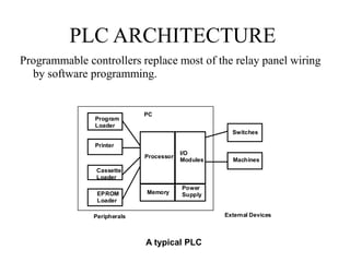
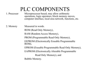
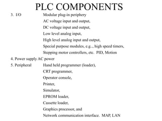
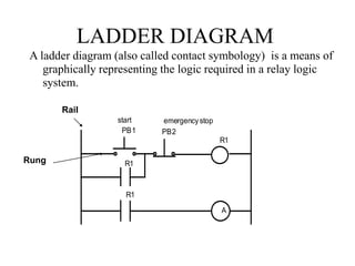
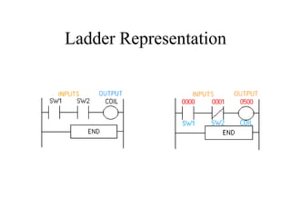
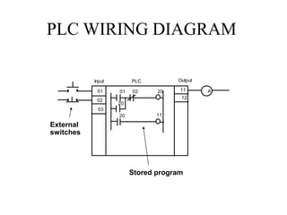
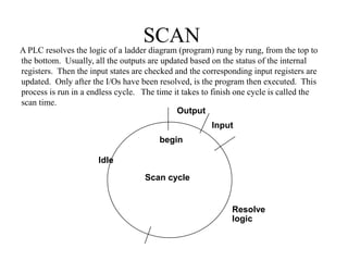
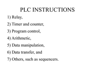
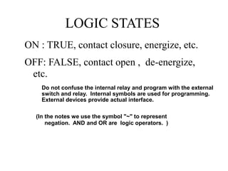
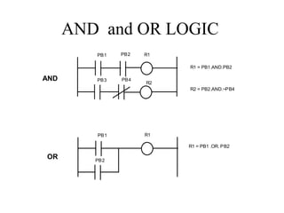
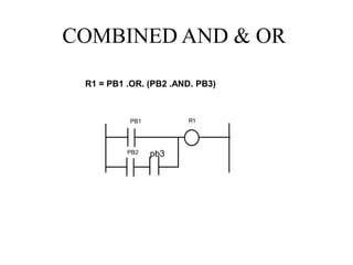
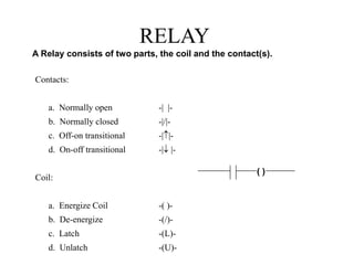
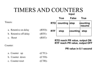
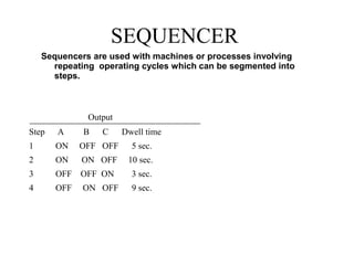
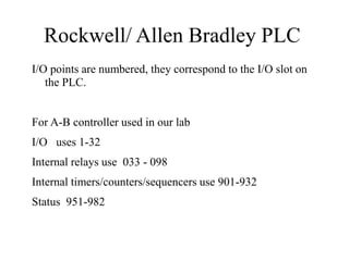
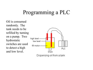
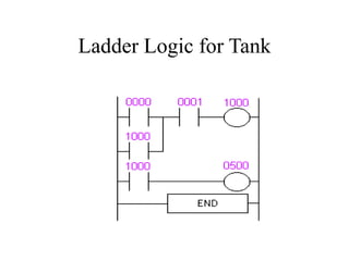
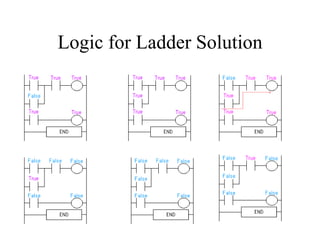
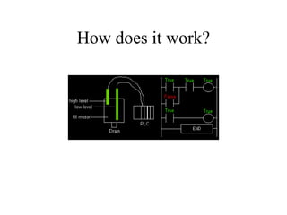
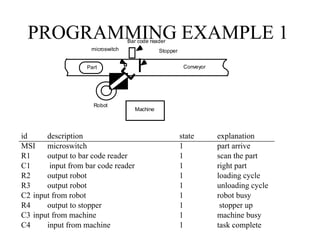
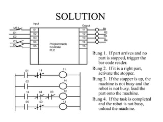
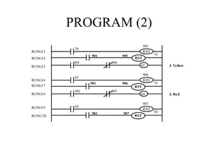
The document provides an overview of programmable logic controllers (PLCs) and their use in manufacturing control systems. It discusses the history and purpose of PLCs, the components that PLCs interact with including input/output devices, and basic PLC programming concepts such as ladder logic, instructions, and logic states. It also provides an example of how a PLC could be programmed and wired to control the filling of an oil tank based on input from two level sensors.