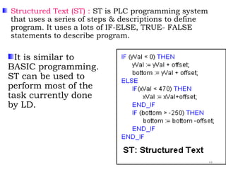
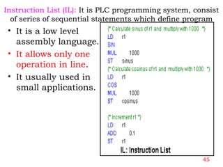
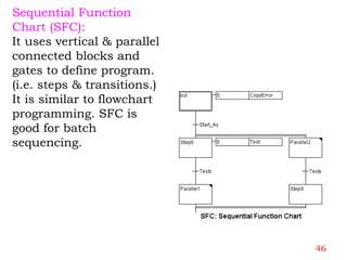
Programmable Logic Controller
(PLC)
Presented By
Prof.Suhas B.Khadake
D.I.E,B.E(E & TC),(M.E)(Electronics)
Lecturer
V.V.P Polytechnic Solapur
1
• Programmable:-It can be changed or
modified
• Logic:-Determines Output based on
input(if this ,then that)
• Controller: Computer
2
Programmable Logic Controller
Definition of a PLC by NEMA (National Electrical
Manufacturers Association):
A P.L.C. is a digitally operated electronic system,
designed for industrial environment, which uses a
programmable memory for the internal storage of user
instructions(program) for implementing specific
functions such as Logic, Sequencing, Timing, Counting,
and Arithmetic, to control through (digital or analog
inputs and outputs), the various types of machines or
processes.
3
Disadvantages of relay control panel:
• It had very large no. of relays, mechanical
switches, timers, counters, hence the wires
required to connect them & also there was
dependencies.
• Mechanical contacts & wires subjected to wear &
tear, so they had limited life span. If replacement
was required the entire unit (process) needed to be
shut down.
• When control requirements changed, relays had to
be added or removed & rewiring was necessary, it
was Very difficult to update.
• If any one device didn’t work properly, it was
difficult to identify the cause of problem.
4
• All above were time consuming & tedious process.
In complex control system complete panel had to be
replaced & it was not economically feasible.
• The increasing sophistication & complexity of
industrial control system & also required more
faster acting control elements. The above relay
control system is not feasible.
5
• To overcome above problems, the Solid State Switching
devices were developed, which were faster, low power
consumption & eliminated much of the hand wiring, no
contact arcing, but solid state devices suffered from
following drawbacks.
- New language comprises of logic gates.
- Low reliability.
- Noise signal could cause the control circuit to
malfunction.
-Solid state devices did not work well at high temperature.
-It was not economically feasible for small control
requirements.
6
-Update was not easy because of change of copper track
connections & addition or removal of solid state
devices.
-Problem of heat dissipation.
-Trouble shooting was difficult as compared to relay
circuit.
-The reluctance of technician to learn new language
comprising logic gates.
Microprocessor & Microcontroller:
Due to development of µp. µp has given PLC to industry.
All logic gates, timer, counters & arithmetic functions
are in PLC through software.
7
Advantages of PLC:
• Use of s/w programming instead of hardware & wires
to control the i/o devices.
• Amount of wiring is cut-down by 80%.
• Faster scan time: Operational time of PLC is very fast
as compare to Relays. The speed of PLC logic
operation is determine by scan time, which is a matter
of millisecond.
• Intelligent I/O s & high speed counters.
• Supervisory control & ASCII message handling
capability.
• Reliability & Maintainability: PLC has very high
reliability rate & hence control system maintenance
cost is low and downtime is minimal.
8
• Flexibility :- Flexibility in programming &
reprogramming in plant. Also flexibility in control
technique. i.e. the control equipment can be easily
reconfigured to accommodate required change in
process online.
• Ability to communicate with computer system in
plant.
• COST :- PLC can scan digital & analog inputs
through relevant sensors. It can execute the logic
w.r.t. the scanned inputs, take necessary decision
and send it to digital / analog outputs. It can also
perform timer, counter, sequencer, PID , and other
control functions. The cost of all this is much less
than a conventional DATA Logger !!
9
• Versatility :- The ability to combine discrete (Digital) &
Analog logic is a powerful tool for the Control
Engineers. Control of critical start-up parameters,
such as temperature and pressure, can be precisely
pre-programmed for each start-up step.
• As one common device (PLC) performs multiple
functions in a Plant, fewer spare parts are needed.
• Programmable troubleshooting aids reduces downtime.
• The software consist of LAD, which is similar to relay
logic, so even technician can maintain the plant.
10
• Expandability :-.
A PLC can easily change the sequence of process
through software and also accommodates the
additional I/O’s without requiring changes in the
existing wiring ( due to modular design).
If a PID loop is to be added, no panel rework is
necessary; only the wiring of new points and some re-
programming to incorporate them is required.
• Rugged Construction - Can operate in Extremely
harsh field conditions.
• Small in physical Size.
11
• Pilot Running :-PLC Programme can be simulated ,tested,
modified at office if needed, which save valuable factory
time.
• PLC provides error checking & diagnostics. It periodically
carry out internal test to its memory, processors & I/O
system through in-built program.
• Simplicity of ordering Control system components.
• Documentation: An immediate printout of true PLC
circuit, list of inputs & outputs and other client
information is available in minutes, if required.
• Security: A PLC program change cannot be made unless
unlocked and programmed.
12
Limitations of PLC
• People reluctance to change( New technology): It is
difficult to change mind set of people to new
technology.
• Environmental Considerations: Certain process
environments, such as high heat, vibrations, noise
level, interference with electronic devices limit the use
of PLC.
• Fixed circuit operation: If circuit in operation is never
altered, a fixed control system might be less costly than
PLC. The PLC is most effective when periodic changes
in operation are made.
13
14
Block diagram of PLC
• The sensing section.
• Input section( I/p module):-Digital/Analog/High Speed.
• Controller( CPU):- Decision Making Unit
• Memory: RAM & ROM.
• Program monitor :PC / Hand held Terminal / Industrial
computer.
• Outputs section (output module): - Digital /Analog
Output field devices.
• Power Supply: - 24 VDC / 110VAC / 220VAC / +/-
12V/ +/-5 v dc.
• Communication - Serial - RS232C / Equivalent /DH-
485
15
The Sensing Section
• This section comprises PB,TS,LS, pressure switches,
sensors & so on. These provide input signals. These
are connected to screw terminals of Input modules.
Each input terminal has a unique identifier called an
input address.
16
Input module:
• There are two types digital & analog input modules.
• It provides interfacing between actual input devices &
PLC.
• It provides conditioning, isolation, terminations &
indications.
• Available voltage range for various applications are
120v ac/240v ac/48v dc/24v dc.
• Input modules have either 8,12,16 or 32 input
terminals depending on PLC.
• The memory storage area for input signals is called
input status file or input image file.
17
Controller (CPU)
• It is brain (µp or µc) of PLC. It is decision maker &
controls the entire process as per user instructions,
reads the status of input devices & store in memory for
latter use by CPU, solve user instructions & update the
status of output image file.
• µp used in processors depends upon number of input
to be monitored & number of output to be controlled.
• Self-contained & modular design.
18
Operating mode of Processor
• Programming mode
• Run mode
• Rem Mode
• What are the operating mode of processor?
Explain? 4 Mark
19
C
P
U
I/P Image file
Variable data memoryUser prg memory
O/p image file
I/p
M
O
D
U
L
E
To
O/p
M
O
D
U
L
E
Block Diagram of Processor
20
Memory
• Two types of memory: A volatile (RAM) & non-volatile
(ROM).
• The information can be written into / read from RAM.
RAM means any memory locations can be accessed
easily.
• CMOS-RAM is used (because of low battery & low power consumption)
for both, as user memory to store program and as
storage memory for storing status of I/Os, values of
timers, counters & other data required for program
execution ( is called data file/table).
• Since RAM is volatile, it is backed up by (lithium) battery
to retain or to protect the stored program.
• User can edit both of above memory
21
Memory
• Non-volatile memory retains information or prg when
power lost. Do not require battery back up.
• In ROM information is written only once & then
information can only read, can’t change.
• In PLC processor, EEPROM used to store OS.
• EEPROM is also used in PLC to load program from RAM
of PLC and program made permanent. It is thus, non-
volatile back up for the user program RAM.
• Memory sizes are often specified in 1K( i.e. 1024 words).
22
Input Image File (Table)
• It is portion of processor memory, where the status of
input devices is stored.
• Every terminal of input module is assigned a particular
address in memory is called input image file.
• The image of status of input devices created before
processor starts executing the user program.
• IMF has acquire information from the input module &
pass on to CPU, when the instruction execution calls
for any input information.
23
24
Output Image File( Table)
• It is portion of processor memory, where the each
output terminal of output module is assign particular
memory address.
• OIF receives information from CPU & pass on to
output module. Also pass information back to CPU,
when any instruction calls the status of particular
output.
25
26
Programming Device or PM
-It is control console for PLC i.e. it is interfacing
between PLC & user. The following functions are
done through PM.
• The program is entered into PLC.
• The editing & troubleshooting of an exiting
program .
• PLC operated in different modes through PM.
-Once the program has been entered into PLC & put
PLC in RUN mode, PM may be disconnected.
-But PM can be use to monitor PLC program while
the program is running.
-PM Can be Dedicated Desktop Programmer( DDP)
or Hand Held Terminal( HHT) or Personal
Computer (PC). 27
Output Module
• There are two types digital & analog output modules.
• It provides interfacing between actual output devices &
PLC.
• It provides conditioning, isolation, terminations &
indications.
• Available voltage range for various applications are 120v
ac/240v ac/48v dc/24v dc.
• Output modules have either 8,12,16 or 32 output
terminals depending on PLC.
• The memory storage area for output signals is called
output status file or output image file.
28
Output Devices
• The output devices are motor starter coil,
relay coils, contactor coils, pilot lights, solenoid valves
etc. These are connected to screw terminals of output
module. Each output terminal has a unique identifier
called an output address.
• The machines or process are controlled by these
devices and these devices are controlled by PLC.
29
Input Devices of PLC
• Push buttons
• Temperature switch
• Limit Switch
• Pressure Switch
• Proximity Switch
• Flow switch
30
Power Supply
• The function of power supply is to supply conditioned
power to the all components of PLC.
• It is critical component because it is non-redundant.
• It contains high voltage components, hence an
insulation failure can be a serious potential for injury
or fire.
31
Communication Port
• The physical connection between a processor &
outside world ( i.e. PC & processor) is called a
communication Port.
• The most of processors have a standard serial port
(RS-232c) plus Data-Highway 485 (DH485) port.
• RS-232C stands for “Recommended Standard” & C for
third version. it is serial communication.
• It uses either a 25 pins or 9 pins D shell connector.
32
Bus System
• The buses provide paths for communication within
PLC. There are three buses ;
• Data bus: It carries data used in processing carried out
by CPU. 8 bit processor handles 8(byte) bits / 16 bit
processor handles 16 bits.
• Address bus: It is used to carry the addresses of
memory locations & every memory location has unique
address. So CPU can read from / write into memory
address. it carries the information indicating which
address is to be accessed.
• Control bus: It carries the signals used by CPU for
control. So CPU synchronized all actions.
33
34
Scan cycle
• Scan cycle (processor scan): input scan, program scan,
output scan, communications & housekeeping.
Program
scan
Input
scan
Output scan
Communication
& HK(Self
Scan)
35
36
Just too hard to compare pricing with so many variables like I/O counts, hardware
needed, programming software, etc.
Cost
This is where the PC excels because
of it's hard drive. Any long term data
storage, history and trending is best
done on a PC.
Memory is limited in its ability to store a lot of
data.
Data
management
A PC is very flexible and powerful in
what to use for programming.
Languages are typically fixed to ladder logic,
function block or structured text or IL
Programming
languages
A PC locking up and crashing is
frequent.
A PLC never crashes over long periods of time.
("Never" may not be the right word but its close
enough to be true.)
Reliability
PCs, by design, are meant to handle
simultaneous tasks. They have
difficulty handling real time events.
PLCs execute a single program in sequential
order. They have better ability to handle events
in real time.
Speed
Typical PCs are limited by the number
of cards they can accommodate and
are not easily expandable.
PLCs in rack form are easy to exchange and add
parts. They are designed for modularity and
expansion.
Flexibility
Operating systems like Windows are
common. Connecting I/O to the PC is
not always as easy.
By design PLCs are friendlier to technicians since
they are in ladder logic and have easy
connections.
Ease of Use
Common PCs are not designed for
harsh environments. Industrial PCs
are available but cost more.
The PLC was specifically designed for harsh
conditions with electrical noise, magnetic fields,
vibration, extreme temperatures or humidity.
Environment
PCPLCÂ
37
Types of PLC
-Dedicated controller:-
A dedicated controller is a single
instrument that is dedicated to
controlling one process, such as a
PID controller measuring a
temperature for heating control.
- In this controller, program &
number of I/Os are fixed.
-.
38
Types of PLC
Fixed PLC:-
It has all of its components such as CPU, memory, power
supply, i/o sections & status lights (LEDS) are built into
one self-contained unit is called fixed or package or micro
PLC.
-.
39
Types of PLC ( cont…)
• Modular PLC:- In this type, different types of modules
such as DI, DO, AI, AO, PS & special modules are housed
in a rack ( chassis) having number of slots.( e.g.
4,7,10,13 ).
40
Programming Languages
• Standard IEC 1131-3( International Electro technical
Commission) gives specifications for programming
languages. It consist of 4 traditional languages & one
high level languages.
Two Graphical Languages : Ladder Diagram (LD),
&Function Block Diagram (FBD).
Two Tex-based Languages : Structured Text (ST) &
Instruction List (IL)
Sequential Function Chart (SFC)
41
Ladder Diagram (LD):
LD programming is similar to relay logic.
 It comprises rungs, I/O instructions & branches as shown in fig.
 Power flow, I/O forcing & on line changes are provided during run
time.
42
Function Block Diagram (FBD):
It is a graphical representation of executable code. It
comprises a series of blocks representing NO/NC inputs
(with addresses or tag), instructions, outputs (with
addresses or tag) connected by lines ( called wire) through
connectors on plane sheet. It is widely used in Europe.
43
Structured Text (ST) : ST is PLC programming system
that uses a series of steps & descriptions to define
program. It uses a lots of IF-ELSE, TRUE- FALSE
statements to describe program.
It is similar to
BASIC programming.
ST can be used to
perform most of the
task currently done
by LD.
44
Instruction List (IL): It is PLC programming system, consist
of series of sequential statements which define program
• It is a low level
assembly language.
• It allows only one
operation in line.
• It usually used in
small applications.
45
Sequential Function
Chart (SFC):
It uses vertical & parallel
connected blocks and
gates to define program.
(i.e. steps & transitions.)
It is similar to flowchart
programming. SFC is
good for batch
sequencing.
46
PLC Manufactures
Allen Bradley, Messung, Siemens, Mitsubishi, Tata
Honeywell, ABB, ALSTOM, FESTO ,Fuji Electric,
Reliance ,B & R , Toshiba, Cutler Hammer, Schneider ,
Koyo, Sigmatek , ,Omron, G.E.Fanuc, Modicon, Omega
Engg., Bechoff, etc.
47
Thank you
48

PLC Introduction Details

  • 1.
    Programmable Logic Controller (PLC) PresentedBy Prof.Suhas B.Khadake D.I.E,B.E(E & TC),(M.E)(Electronics) Lecturer V.V.P Polytechnic Solapur 1
  • 2.
    • Programmable:-It canbe changed or modified • Logic:-Determines Output based on input(if this ,then that) • Controller: Computer 2
  • 3.
    Programmable Logic Controller Definitionof a PLC by NEMA (National Electrical Manufacturers Association): A P.L.C. is a digitally operated electronic system, designed for industrial environment, which uses a programmable memory for the internal storage of user instructions(program) for implementing specific functions such as Logic, Sequencing, Timing, Counting, and Arithmetic, to control through (digital or analog inputs and outputs), the various types of machines or processes. 3
  • 4.
    Disadvantages of relaycontrol panel: • It had very large no. of relays, mechanical switches, timers, counters, hence the wires required to connect them & also there was dependencies. • Mechanical contacts & wires subjected to wear & tear, so they had limited life span. If replacement was required the entire unit (process) needed to be shut down. • When control requirements changed, relays had to be added or removed & rewiring was necessary, it was Very difficult to update. • If any one device didn’t work properly, it was difficult to identify the cause of problem. 4
  • 5.
    • All abovewere time consuming & tedious process. In complex control system complete panel had to be replaced & it was not economically feasible. • The increasing sophistication & complexity of industrial control system & also required more faster acting control elements. The above relay control system is not feasible. 5
  • 6.
    • To overcomeabove problems, the Solid State Switching devices were developed, which were faster, low power consumption & eliminated much of the hand wiring, no contact arcing, but solid state devices suffered from following drawbacks. - New language comprises of logic gates. - Low reliability. - Noise signal could cause the control circuit to malfunction. -Solid state devices did not work well at high temperature. -It was not economically feasible for small control requirements. 6
  • 7.
    -Update was noteasy because of change of copper track connections & addition or removal of solid state devices. -Problem of heat dissipation. -Trouble shooting was difficult as compared to relay circuit. -The reluctance of technician to learn new language comprising logic gates. Microprocessor & Microcontroller: Due to development of µp. µp has given PLC to industry. All logic gates, timer, counters & arithmetic functions are in PLC through software. 7
  • 8.
    Advantages of PLC: •Use of s/w programming instead of hardware & wires to control the i/o devices. • Amount of wiring is cut-down by 80%. • Faster scan time: Operational time of PLC is very fast as compare to Relays. The speed of PLC logic operation is determine by scan time, which is a matter of millisecond. • Intelligent I/O s & high speed counters. • Supervisory control & ASCII message handling capability. • Reliability & Maintainability: PLC has very high reliability rate & hence control system maintenance cost is low and downtime is minimal. 8
  • 9.
    • Flexibility :-Flexibility in programming & reprogramming in plant. Also flexibility in control technique. i.e. the control equipment can be easily reconfigured to accommodate required change in process online. • Ability to communicate with computer system in plant. • COST :- PLC can scan digital & analog inputs through relevant sensors. It can execute the logic w.r.t. the scanned inputs, take necessary decision and send it to digital / analog outputs. It can also perform timer, counter, sequencer, PID , and other control functions. The cost of all this is much less than a conventional DATA Logger !! 9
  • 10.
    • Versatility :-The ability to combine discrete (Digital) & Analog logic is a powerful tool for the Control Engineers. Control of critical start-up parameters, such as temperature and pressure, can be precisely pre-programmed for each start-up step. • As one common device (PLC) performs multiple functions in a Plant, fewer spare parts are needed. • Programmable troubleshooting aids reduces downtime. • The software consist of LAD, which is similar to relay logic, so even technician can maintain the plant. 10
  • 11.
    • Expandability :-. APLC can easily change the sequence of process through software and also accommodates the additional I/O’s without requiring changes in the existing wiring ( due to modular design). If a PID loop is to be added, no panel rework is necessary; only the wiring of new points and some re- programming to incorporate them is required. • Rugged Construction - Can operate in Extremely harsh field conditions. • Small in physical Size. 11
  • 12.
    • Pilot Running:-PLC Programme can be simulated ,tested, modified at office if needed, which save valuable factory time. • PLC provides error checking & diagnostics. It periodically carry out internal test to its memory, processors & I/O system through in-built program. • Simplicity of ordering Control system components. • Documentation: An immediate printout of true PLC circuit, list of inputs & outputs and other client information is available in minutes, if required. • Security: A PLC program change cannot be made unless unlocked and programmed. 12
  • 13.
    Limitations of PLC •People reluctance to change( New technology): It is difficult to change mind set of people to new technology. • Environmental Considerations: Certain process environments, such as high heat, vibrations, noise level, interference with electronic devices limit the use of PLC. • Fixed circuit operation: If circuit in operation is never altered, a fixed control system might be less costly than PLC. The PLC is most effective when periodic changes in operation are made. 13
  • 14.
  • 15.
    Block diagram ofPLC • The sensing section. • Input section( I/p module):-Digital/Analog/High Speed. • Controller( CPU):- Decision Making Unit • Memory: RAM & ROM. • Program monitor :PC / Hand held Terminal / Industrial computer. • Outputs section (output module): - Digital /Analog Output field devices. • Power Supply: - 24 VDC / 110VAC / 220VAC / +/- 12V/ +/-5 v dc. • Communication - Serial - RS232C / Equivalent /DH- 485 15
  • 16.
    The Sensing Section •This section comprises PB,TS,LS, pressure switches, sensors & so on. These provide input signals. These are connected to screw terminals of Input modules. Each input terminal has a unique identifier called an input address. 16
  • 17.
    Input module: • Thereare two types digital & analog input modules. • It provides interfacing between actual input devices & PLC. • It provides conditioning, isolation, terminations & indications. • Available voltage range for various applications are 120v ac/240v ac/48v dc/24v dc. • Input modules have either 8,12,16 or 32 input terminals depending on PLC. • The memory storage area for input signals is called input status file or input image file. 17
  • 18.
    Controller (CPU) • Itis brain (µp or µc) of PLC. It is decision maker & controls the entire process as per user instructions, reads the status of input devices & store in memory for latter use by CPU, solve user instructions & update the status of output image file. • µp used in processors depends upon number of input to be monitored & number of output to be controlled. • Self-contained & modular design. 18
  • 19.
    Operating mode ofProcessor • Programming mode • Run mode • Rem Mode • What are the operating mode of processor? Explain? 4 Mark 19
  • 20.
    C P U I/P Image file Variabledata memoryUser prg memory O/p image file I/p M O D U L E To O/p M O D U L E Block Diagram of Processor 20
  • 21.
    Memory • Two typesof memory: A volatile (RAM) & non-volatile (ROM). • The information can be written into / read from RAM. RAM means any memory locations can be accessed easily. • CMOS-RAM is used (because of low battery & low power consumption) for both, as user memory to store program and as storage memory for storing status of I/Os, values of timers, counters & other data required for program execution ( is called data file/table). • Since RAM is volatile, it is backed up by (lithium) battery to retain or to protect the stored program. • User can edit both of above memory 21
  • 22.
    Memory • Non-volatile memoryretains information or prg when power lost. Do not require battery back up. • In ROM information is written only once & then information can only read, can’t change. • In PLC processor, EEPROM used to store OS. • EEPROM is also used in PLC to load program from RAM of PLC and program made permanent. It is thus, non- volatile back up for the user program RAM. • Memory sizes are often specified in 1K( i.e. 1024 words). 22
  • 23.
    Input Image File(Table) • It is portion of processor memory, where the status of input devices is stored. • Every terminal of input module is assigned a particular address in memory is called input image file. • The image of status of input devices created before processor starts executing the user program. • IMF has acquire information from the input module & pass on to CPU, when the instruction execution calls for any input information. 23
  • 24.
  • 25.
    Output Image File(Table) • It is portion of processor memory, where the each output terminal of output module is assign particular memory address. • OIF receives information from CPU & pass on to output module. Also pass information back to CPU, when any instruction calls the status of particular output. 25
  • 26.
  • 27.
    Programming Device orPM -It is control console for PLC i.e. it is interfacing between PLC & user. The following functions are done through PM. • The program is entered into PLC. • The editing & troubleshooting of an exiting program . • PLC operated in different modes through PM. -Once the program has been entered into PLC & put PLC in RUN mode, PM may be disconnected. -But PM can be use to monitor PLC program while the program is running. -PM Can be Dedicated Desktop Programmer( DDP) or Hand Held Terminal( HHT) or Personal Computer (PC). 27
  • 28.
    Output Module • Thereare two types digital & analog output modules. • It provides interfacing between actual output devices & PLC. • It provides conditioning, isolation, terminations & indications. • Available voltage range for various applications are 120v ac/240v ac/48v dc/24v dc. • Output modules have either 8,12,16 or 32 output terminals depending on PLC. • The memory storage area for output signals is called output status file or output image file. 28
  • 29.
    Output Devices • Theoutput devices are motor starter coil, relay coils, contactor coils, pilot lights, solenoid valves etc. These are connected to screw terminals of output module. Each output terminal has a unique identifier called an output address. • The machines or process are controlled by these devices and these devices are controlled by PLC. 29
  • 30.
    Input Devices ofPLC • Push buttons • Temperature switch • Limit Switch • Pressure Switch • Proximity Switch • Flow switch 30
  • 31.
    Power Supply • Thefunction of power supply is to supply conditioned power to the all components of PLC. • It is critical component because it is non-redundant. • It contains high voltage components, hence an insulation failure can be a serious potential for injury or fire. 31
  • 32.
    Communication Port • Thephysical connection between a processor & outside world ( i.e. PC & processor) is called a communication Port. • The most of processors have a standard serial port (RS-232c) plus Data-Highway 485 (DH485) port. • RS-232C stands for “Recommended Standard” & C for third version. it is serial communication. • It uses either a 25 pins or 9 pins D shell connector. 32
  • 33.
    Bus System • Thebuses provide paths for communication within PLC. There are three buses ; • Data bus: It carries data used in processing carried out by CPU. 8 bit processor handles 8(byte) bits / 16 bit processor handles 16 bits. • Address bus: It is used to carry the addresses of memory locations & every memory location has unique address. So CPU can read from / write into memory address. it carries the information indicating which address is to be accessed. • Control bus: It carries the signals used by CPU for control. So CPU synchronized all actions. 33
  • 34.
  • 35.
    Scan cycle • Scancycle (processor scan): input scan, program scan, output scan, communications & housekeeping. Program scan Input scan Output scan Communication & HK(Self Scan) 35
  • 36.
  • 37.
    Just too hardto compare pricing with so many variables like I/O counts, hardware needed, programming software, etc. Cost This is where the PC excels because of it's hard drive. Any long term data storage, history and trending is best done on a PC. Memory is limited in its ability to store a lot of data. Data management A PC is very flexible and powerful in what to use for programming. Languages are typically fixed to ladder logic, function block or structured text or IL Programming languages A PC locking up and crashing is frequent. A PLC never crashes over long periods of time. ("Never" may not be the right word but its close enough to be true.) Reliability PCs, by design, are meant to handle simultaneous tasks. They have difficulty handling real time events. PLCs execute a single program in sequential order. They have better ability to handle events in real time. Speed Typical PCs are limited by the number of cards they can accommodate and are not easily expandable. PLCs in rack form are easy to exchange and add parts. They are designed for modularity and expansion. Flexibility Operating systems like Windows are common. Connecting I/O to the PC is not always as easy. By design PLCs are friendlier to technicians since they are in ladder logic and have easy connections. Ease of Use Common PCs are not designed for harsh environments. Industrial PCs are available but cost more. The PLC was specifically designed for harsh conditions with electrical noise, magnetic fields, vibration, extreme temperatures or humidity. Environment PCPLCÂ 37
  • 38.
    Types of PLC -Dedicatedcontroller:- A dedicated controller is a single instrument that is dedicated to controlling one process, such as a PID controller measuring a temperature for heating control. - In this controller, program & number of I/Os are fixed. -. 38
  • 39.
    Types of PLC FixedPLC:- It has all of its components such as CPU, memory, power supply, i/o sections & status lights (LEDS) are built into one self-contained unit is called fixed or package or micro PLC. -. 39
  • 40.
    Types of PLC( cont…) • Modular PLC:- In this type, different types of modules such as DI, DO, AI, AO, PS & special modules are housed in a rack ( chassis) having number of slots.( e.g. 4,7,10,13 ). 40
  • 41.
    Programming Languages • StandardIEC 1131-3( International Electro technical Commission) gives specifications for programming languages. It consist of 4 traditional languages & one high level languages. Two Graphical Languages : Ladder Diagram (LD), &Function Block Diagram (FBD). Two Tex-based Languages : Structured Text (ST) & Instruction List (IL) Sequential Function Chart (SFC) 41
  • 42.
    Ladder Diagram (LD): LDprogramming is similar to relay logic.  It comprises rungs, I/O instructions & branches as shown in fig.  Power flow, I/O forcing & on line changes are provided during run time. 42
  • 43.
    Function Block Diagram(FBD): It is a graphical representation of executable code. It comprises a series of blocks representing NO/NC inputs (with addresses or tag), instructions, outputs (with addresses or tag) connected by lines ( called wire) through connectors on plane sheet. It is widely used in Europe. 43
  • 44.
    Structured Text (ST): ST is PLC programming system that uses a series of steps & descriptions to define program. It uses a lots of IF-ELSE, TRUE- FALSE statements to describe program. It is similar to BASIC programming. ST can be used to perform most of the task currently done by LD. 44
  • 45.
    Instruction List (IL):It is PLC programming system, consist of series of sequential statements which define program • It is a low level assembly language. • It allows only one operation in line. • It usually used in small applications. 45
  • 46.
    Sequential Function Chart (SFC): Ituses vertical & parallel connected blocks and gates to define program. (i.e. steps & transitions.) It is similar to flowchart programming. SFC is good for batch sequencing. 46
  • 47.
    PLC Manufactures Allen Bradley,Messung, Siemens, Mitsubishi, Tata Honeywell, ABB, ALSTOM, FESTO ,Fuji Electric, Reliance ,B & R , Toshiba, Cutler Hammer, Schneider , Koyo, Sigmatek , ,Omron, G.E.Fanuc, Modicon, Omega Engg., Bechoff, etc. 47
  • 48.