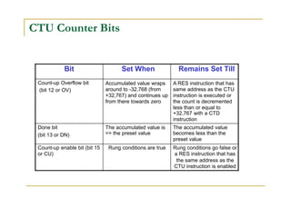
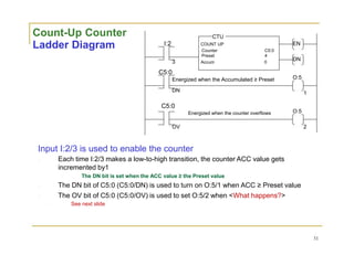
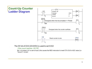
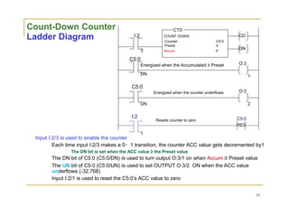
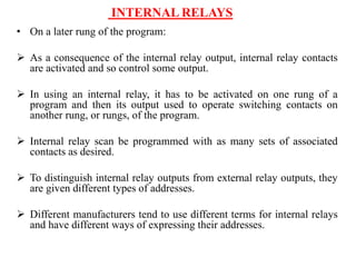
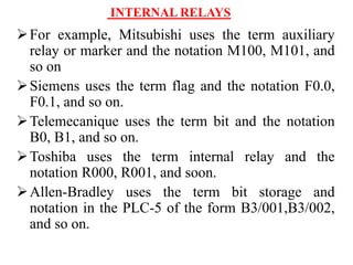
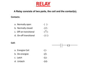
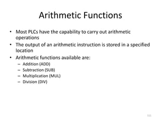
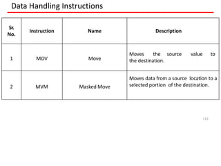
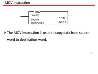
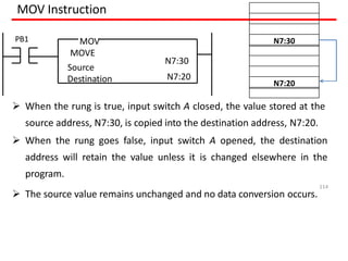
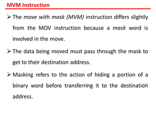
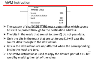
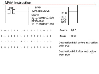
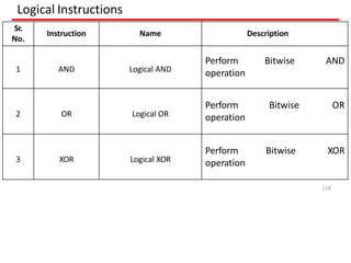
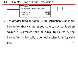
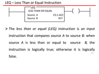
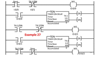
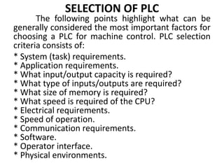
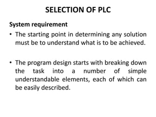
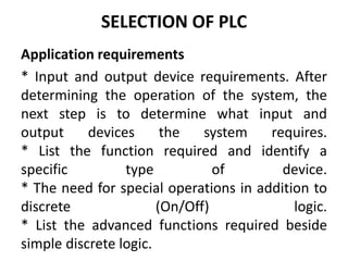
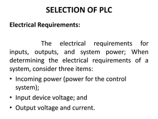
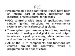
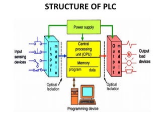
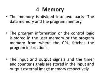
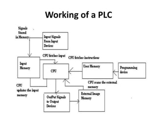
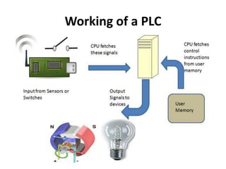
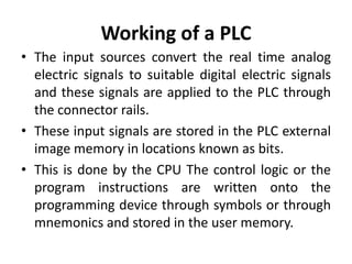
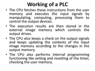
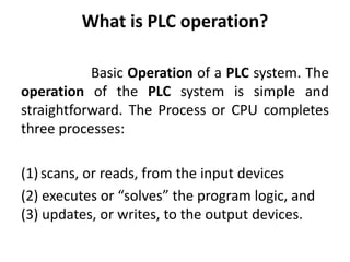
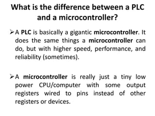
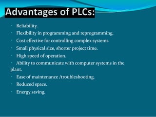
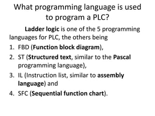
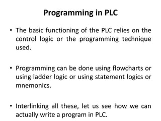
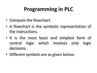
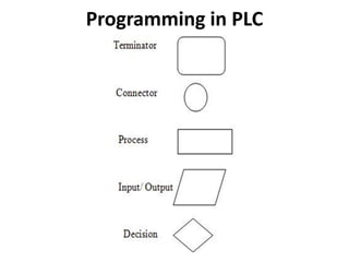
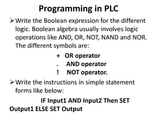
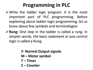
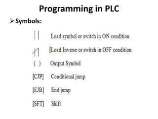
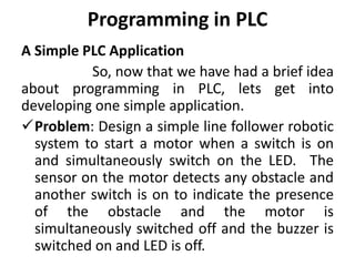
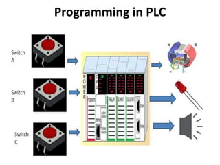
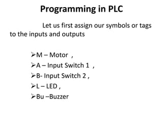
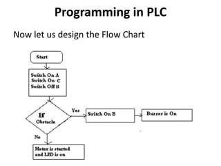
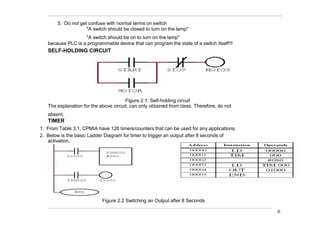
This document provides an introduction to Programmable Logic Controllers (PLCs). It discusses the history and evolution of control systems from humans to relays to PLCs. The key components of a PLC including the input/output modules, central processing unit, memory, and programming terminal are described. Programming methods for PLCs such as ladder logic, Boolean expressions, and mnemonics are also introduced. Examples of using timers, counters, and internal relays in PLC programs are provided.

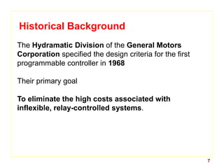
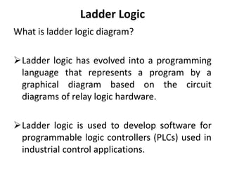


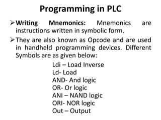

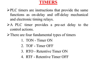
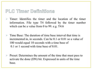
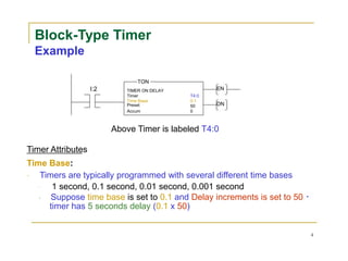
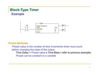
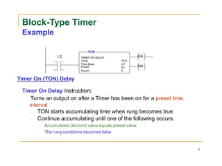
![Block-Type Timer
Example
TON
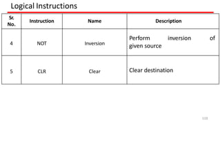
I:2 TIMER ON DELAY EN
Timer T4:0
Time Base 0.1
Preset 50 DN
Accum 0
Accum Attribute:
[Rockwell] Timers have one input. When the input transits from low
to high, the timer will begin timing (Accum value)
Timers that do not lose their accumulated time when the enable input line
transitions to low again are known as Retentive Timers
Retentive Timers continue to maintain accumulated time and increment
the time when the input line goes to high again
Non-retentive Timers lose the accumulated time whenever the enable
input transitions to low
The accumulated time resets to zero
6](https://image.slidesharecdn.com/unit4-211006040644/85/Introduction-to-PLC-70-320.jpg)